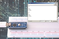
Arduino Serial
A complete look at using serial UART with the Arduino. All the way from the very basics to the advanced features and functions.


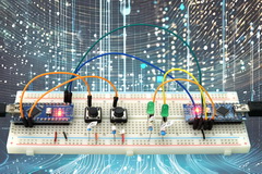
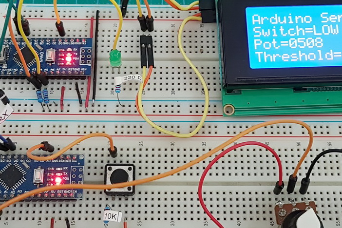
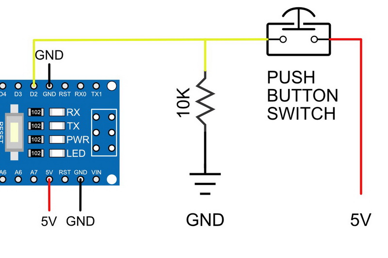
Switching Things On And Off With An Arduino
One of the first projects many people start with is to turn on/off or blink an LED and there many many guides on line that show how to do this. Unfortunately, many of the guides never go beyond the very basic first sketch. In this guide, I hope to help with the next step with on/off switches, toggle switches, and controlling multiple states from a single switch.

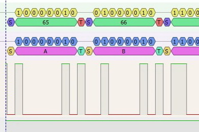
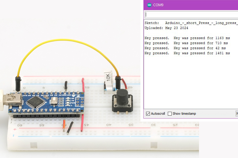
Arduino Long Press Short Press
Want to use long presses and short presses? First start with timing how long the button was pressed then go for it.
Switching High Voltages With An Arduino
Bored with blinking an LED. Time to let the Arduino control high voltage devices such as solenoid valves and motors. Much of the code is the same as in the Switching Things On and Off guides, however, the circuit is not as straight forward as using an LED.
General Arduino Topics
Guides and posts that don’t fit any where else.
DIY Arduino On a Breadboard
Build your own Arduino compatible controller on a breadboard.


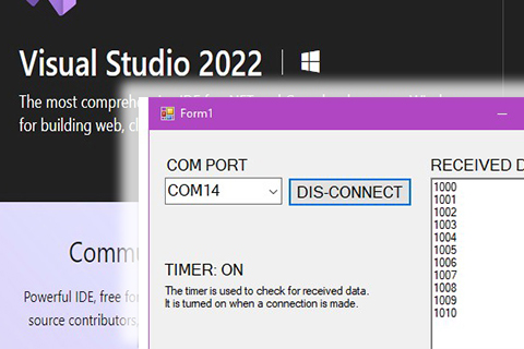
Arduino & Visual Basic
A 3 part series introducing serial communication between an Arduino and Visual Basic Net running on a Windows PC.


Bluetooth
A collection guides and notes which I am slowly updating.


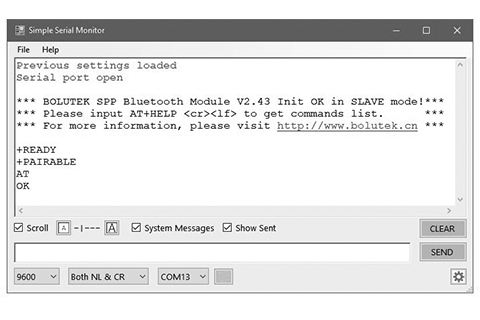
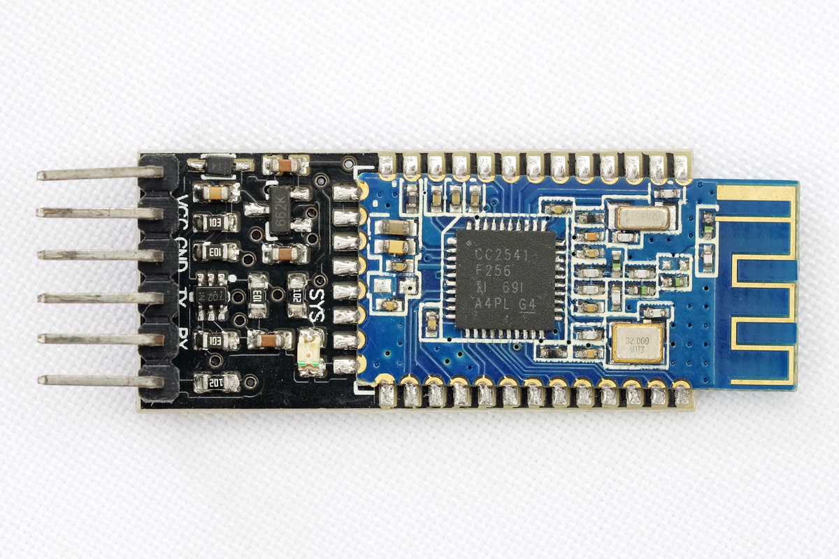
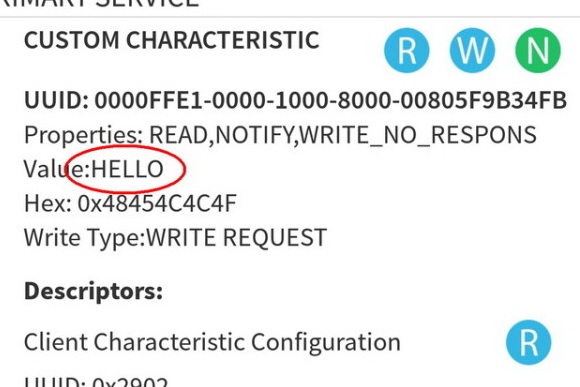
HM-10
All your HM-10 needs in one place.
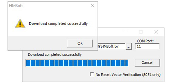


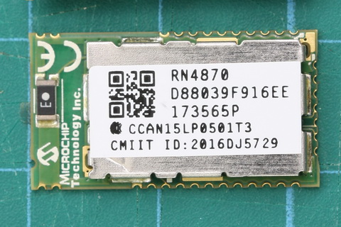
RN4870/1
More Bluetooth
HC-06 and HC-05 Bluetooth
HC-05 and HC-06 zs-040 Bluetooth modules. First Look
HC-06 (ZS-040) Introduction
Arduino With HC-05 Bluetooth Module in Slave Mode
Arduino with HC-05 (ZS-040) Bluetooth module – AT MODE
Connecting 2 Arduinos by Bluetooth using a HC-05 and a HC-06: Easy Method Using CMODE
Connecting 2 Arduinos by Bluetooth using a HC-05 and a HC-06: Pair, Bind, and Link
FC-144 HC-05 and HC-06
HC-05 FC-114 and HC-06 FC-114. First Look
HC-05 FC-114 and HC-06 FC-114. Part 2 – Basic AT commands
HC-05 FC-114 and HC-06 FC-114. Part 3 – Master Mode and Auto Connect
Remote Control using Bluetooth and Android
Turning a LED on and off with an Arduino, a HC-06 and Android
Control an Arduino from an Android App. arduinoBTcontrol
Arduino To Arduino by Bluetooth
Arduino to Arduino by Bluetooth
Arduino, App inventor and Bluetooth Classic
Turning a LED on and off part 1. Basic LED control.
Turning a LED on and off part 2.. Now with 2 way control.
Turning a LED on and off part 3. 2 way control with 3 LEDs with 3 switches
arduinoBTcontrol. Various controls and events
App inventor and Bluetooth Classic
App Inventor – Auto Connect To Bluetooth on start
App Inventor 2 Pseudo Screens
Create A Bluetooth Joypad With App Inventor 2
ESP8266 and the Arduino IDE
Part 1: ESP8266 and the Arduino IDE Using the Esp8266 with the Arduino IDE (Updated)
Part 2: Control an LED from a web page using Access Point Mode (AP)
Part 3: Control an LED from a web page using Station Mode (ST)
Part 4: Connecting to an ESP8266 with unknown IP address using mDNS
Part 5: adding wifiManager
Part 6: JavaScript and AJAX
Part 7: More Controls. 3 LEDs
Part 8: Auto Updating Webpage
Part 9: first steps with Websockets
Part 10a: IOT Website. Temperature and Humidity Monitor
Part 10b: IOT Website. Enhancing the Website
Part 10c: IOT Website. IOT Monitor Station. Add a LCD
Part 10d: IOT Monitor, the final project
ESP8266-01 Programming Breakout Board. Includes 3.3 voltage regulator for power, voltage divider for RX and switches for reset and programming.
Basic connection guide.
ESP8266 + serial adaptor
Arduino to ESP8266 By Serial Communication
Arduino & ESP8266 Webserver. An old example of a webserver using AT commands, can be done but very clunky and slow. Much better to now use the Arduino IDE. Useful if you want to know what is happening behind the scenes when using a library.