Note added 24.03.2017
Added a download for the aia file. See the very bottom of the post.
Note added 28.01.2016
The ABC app is a simple app that I first created to allow me to monitor Arduino pins and to give me basic control functions. It isn’t designed for complex control. I have received many comments and suggestions about the ABC app and as a result I created the new Bluetooth Control Panel app. This features better control functions and was designed around the function rather than the Arduino pin.
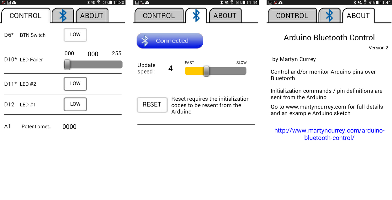
Arduino Bluetooth Control is a simple to use Android app for controlling and/or monitoring Arduino pins over Bluetooth. The app is self contained and all initialization is done from the Arduino sketch. It is designed around Arduino pins rather than control function.
24.10.2015
Now updated to version 2.
Added facility for renaming the pin descriptions and the app now has better error reporting for bad initialization commands
07.12.2015
Update to the sketches. I was checking the elapsed time incorrectly. Took me longer than it should have to spot it.
14.02.2016
Updated to version 3.
The app now sends a <RESET> code when the RESET button is clicked. This allows the Arduino to detect the app reset and automatically resend the initiation commands. See below for an example sketch.
Different configurations
Only the pins you are using (have initialized) are displayed.
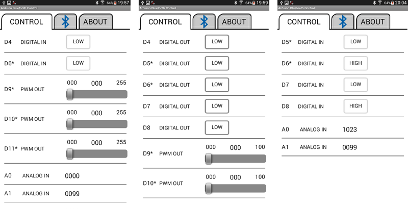
There are 3 kinds of pin:
– Digital Pins
– PWM Pins
– Analogue Pins
Digital Pins
– Digital pins range from D2 to D12.
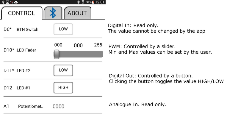
– Digital pins can be input or output.
– The value can be set to HIGH or LOW.
– The pin state can be controlled by the Arduino and the value displayed by the Android app.
– The pin state can be controlled by the Android app.
PWM Pins
– The PWM pins are; D3, D5, D6,D9, D10, and D11
– PWN pins are output only.
– The PWM Pin value is controlled by a slider in the Android app.
– The minimum and maximum values can be set for each pin.
– The smallest minimum is 0.
– The largest maximum is 255.
Analogue Pins
– The analogue pins are A0 to A5.
– Analogue pins are input only.
– The value, from 0 to 1023, is displayed in the Android app.
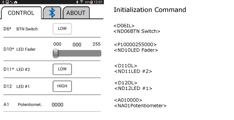
Initialization Commands
The Arduino sends initialization commands to the Android app and this means how the app displays a pin depends on the initialization command sent from the Arduino.
Examples of initialization commands
<D04IL> – Initialize pin D4 for digital input, start value LOW
<P10000255041> – Initialize pin D10 for PWN. Min value is 0. Max value is 255. Start value is 41.
<D11OH> – Initialize pin D11 for digital output, start value HIGH
<D12OH> – Initialize pin D12 for digital output, start value HIGH
<A010102> – Initialize pin A1 for analogue in. Start value is 102.
Initialization Commands For Digital Pins
The initialization command for a digital pin is 5 characters (not including the start and end markers).
The 1st character is the pin type. D for digital
The 2nd and 3rd characters are the pin number. The pin number always uses 2 digits.
The 4th character defines if the pin is input or output. I for input. O for output.
The final character is the start value. This is the value displayed in the Android app when it first starts, not the actual value of the pin. H for high. L for LOW.
<D06OL>
D – pin type. D for digital
06 – the pin number
O – Input or output. O for output
L – starting value. L for LOW
<D12DIH>
D – digital
12 – the pin number
I = input
H = Starting value of HIGH
Initialization Commands For PWM Pins
The initialization commands for PWM pins are 12 characters long not including the start and end markers.
The 1st character is the pin type. P for PWM
The 2nd and 3rd characters are the pin number. The pin number always uses 2 digits.
The 4th, 5th and 6th characters are the minimum value for the slider. 000 to 255.
The 7th, 8th and 9th characters are the maximum value for the slider. 000 to 255.
The 10th, 11th and 12th characters are the starting value of the slider. 000 to 255.
<P10000255000>
P – pin type. P fop PWM
10 – the pin number
000 – the minimum value
255 – the maximum value
000 – the starting value
<P05000100050>
P – PWM
05 – the pin number
000 – the minmium value
100 – the maximum value
050 – the start value
Initialization Commands For Analogue Pins
The initialization command for analogue pins are 7 characters long not including the start and end markers.
The 1st character is the pin type. A for Analogue.
The 2nd and 3rd characters are the pin number. The pin number always uses 2 digits.
The 3rd, 4th, 5th and 6th characters are the starting value displayed in the Android app.
<A011023>
A – analogue
01 – the pin number
1023 – the starting value to be displayed by the Android app.
Pin Description / Name Command
The default pin descriptions are:
– Digital in
– Digital out
– Analog in
– PWM out
These can be changed using the “Name” command.
<ND06LED>
N – for Name
D06 – the pin
LED – the name or description you wish to give to the pin
All pins have a default description which is applied when the pin is initialized. If you initialize a pin after changing its name, the given name will be over written by the default name.
Number of Commands Command
The final command is the “Number of commands” command. This is used by the Android app to check whether or not it has received all the initialization commands correctly. The command is C followed by the number of commands.
<C7>
C – Number of commands (count)
7 – the number of commands not including itself.
The count command is used to check that all commands have been received by the app. If the app does not receive the number of commands specified by the count command then an error message will be displayed.
The number is the number of commands not including the “Number of commands” command.
After the app has been set up you can send and receive pin values. This is done via pin data commands
If an incorrect command is received by the Android app an error message will be displayed and the command will be ignored. If the app does not display a pin check the initialization commands for errors.
If you reset the Arduino while the Android app is running you will also need to reset the app. The app will continue to run but the pin values will not be updated. Either restart the app or click the reset button on the Bluetooth page.
Pin Data Commands
There are 2 types of pin data:
1. Those sent from the Arduino to the Android app.
2. Those sent from the app to the Arduino.
Sending data from the Arduino to the Android app.
There are 2 types of pin data that can be sent from the Arduino
1. Digital Pin Data
2. Analogue Pin Data
Pin data commands sent from the Arduino use [ and ] as start and end markers.
Digital pins can be either HIGH or LOW. The command is shortened to H or L.
For digital pins the command is basically the pin number and the status.
[D04H] – pin D4 is HIGH
[D04L] – pin D4 is LOW
The commands are then sent to the Android app with:
BTserial.print("[D04H]"); BTserial.print("[D04L]"); |
Analogue pins can have a value from 0 to 1023. The value should be converted to a string before sending to the app.
For analogue pins the command is the pin number plus the value sent as a string.
[A010000]
A01 – Analogue pin 1
Value = 0000
[A021023]
A02 – Analogue pin 2
Value = 1023
The command is sent to the Android app in the same way as the digital command:
BTserial.print("[A011023]"); |
Note that the value is always 4 digits.
Receiving data on the Arduino from the the Android app
There are 2 types of data command that can be received from the Android app.
1. Digital pin data
2. PWM pin data
Digital pin data
When a digital pin button is clicked in the Android app either a HIGH command or a LOW command is sent to the Arduino. The pin data command consists of the pin number plus the value, H for HIGH. L for LOW.
<D12H> – set pin D12 to HIGH
<D12L> – set pin D12 to LOW
It is up to the sketch to interpret the commands and act accordingly. IE actually set the pin HIGH or LOW using digitalWrite().
PWM pin data
PWN values can be between 0 and 255 (unless you have set different limits) and the command is the pin number plus the value:
<P10000> – set pin D10 to an output of 0
<P10255> – set pin D10 to an output of 255
Remember that the commands do not do anything unless you actually write the value to the pin using analogWrite();
The received command is stored in the receivedChars global variable and you will need to check this to see what the pin number is and what the value is. Note that the start and end markers are stripped away so receivedChars contains only the actual command.
P10000
P10255
The value is always 3 digits.
Example 1: Turning an LED on and off
This example uses a single LED on Pin 12. The LEd is controlled via the Android app.
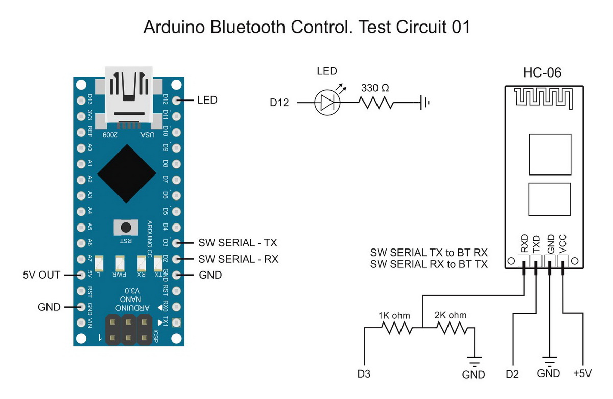
Test Circuit 01. Single LED
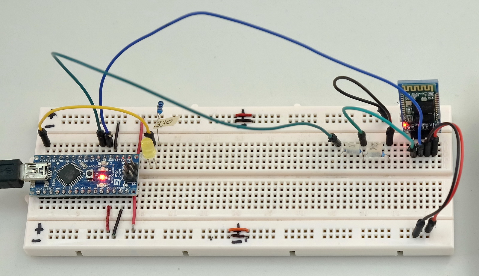
The bluetooth module is a HC-06 set for 9600 baud rate. You can use different baud rates if you wish. Match the baud rate in the sketch with the baud rate of your Bluetooth device. A HC-05 can be used as well.
Example 01. Controlling a single LED
There are 2 parts to setting up the pins in the sketch.
1. Set the pin function
2. Send the initialization command
Set the pin function
This is the regular Arduino pin set up.
// Set the LED pin to output and set LOW pinMode(12, OUTPUT); digitalWrite(12,LOW); |
Send the initialization command
Send the commands to the Android app. The commands tell the app which pins are input and which pins are output.
The initialization commands start with a <START> command and end with an <END> commands
BTserial.print("<START>"); BTserial.print("<D12OL>"); BTserial.print("<C1>"); BTserial.print("<END>"); |
Pin 12 is set to digital out with an initial value of LOW.
BTserial.print("<C1>"); |
C1 is the number of commands (not including iteself in the count) and is used as a check by the app to see if all commands were received correctly.
The Android app counts the number of initialization commands it receives and if this total does not match the total number of commands initialization commands (C1) an error message is displayed. The number of commands does not include the <START> and <END> markers.
On start up, the sketch keeps sending the initialization commands until it receives an “OK” reply from the Android app. Once a reply is received the app starts sending and receiving pin value data.
It is worth noting that the sketch doesn’t know if Bluetooth is connected or not.
Main Functions
recvWithStartEndMarkers() – this checks the software serial in and takes any data that is between the start and end markers (< and >). Any data not within the markers is ignored. The received data is put in to the global variable receivedChars
processCommand() – this checks the received data and if the pin number matches the pin we are using (D12) it is set HIGH or LOW to turn the LED either on or off.
/* * Sketch: ArduinoSketch_ArduinoBluetoothControl_example001_single_LED_b * By Martyn Currey * 01.07.2015 * updated 06.12.2015 * Written in Arduino IDE 1.6.3 * * Requires the Arduino Bluetooth Control Android App. Can be downloaded from Google Play. * See https://www.martyncurrey.com/arduino-bluetooth-control/ * * Turn an LED on and off from an Android app * Uses the following pins * * D2 - software serial RX * D3 - software serial TX * D12 - LED * */ // The Bluetooth module is connected to pin D2 and D3 and uses software serial // Remember to use a voltage divider on the TX pin #include <SoftwareSerial.h> SoftwareSerial BTserial(2,3); // RX | TX // Change DEBUG to true to output debug information to the serial monitor const boolean DEBUG = true; // Variables used for incoming data char rc = ' '; const byte maxDataLength = 20; char receivedChars[21] ; boolean newData = false; void setup() { // Set the LED pin to output pinMode(12, OUTPUT); digitalWrite(12,LOW); if (DEBUG) { // open serial communication for debugging Serial.begin(9600); Serial.println("Sketch: ArduinoSketch_ArduinoBluetoothControl_example001_single_LED_b"); Serial.println(" "); } // open software serial connection to the Bluetooth module BTserial.begin(9600); // Send initialization commands and the wait for a receipt newData = false; boolean done = false; unsigned long startTime = millis(); // keep sending the initialization commands until ew receive an "OK" while (!done) { // send the initialization commands once every second. This can be changed to suit your own sketch. if ( millis()-startTime > 1000) { startTime = millis(); BTserial.print("<START>"); // Start marker BTserial.print("<D12OL>"); // Initialize D12 for output. Start value = LOW BTserial.print("<C1>"); // number of commands not including this one BTserial.print("<END>"); // End marker if (DEBUG) { Serial.println( "Initialization commands sent. Waiting for reply" ); } } recvWithStartEndMarkers(); // check for new data from the Bluetooth module if (newData) { // After the Android app receives the commands it sends an "OK" back. if ( (receivedChars[0] == 'O') & (receivedChars[1] == 'K') ) { done = true; } else {newData = false; } if (DEBUG) { Serial.print("receivedChars = "); Serial.println( receivedChars ); } } } // while (!done) if (DEBUG) { Serial.println("OK received from the app"); } } // void setup() void loop() { recvWithStartEndMarkers(); // check to see if we have received any new commands if (newData) { processCommand(); } // if we have a new command do something } /* **************************************** * Function processCommand * parses data commands contained in receivedChars[] * receivedChars[] has not been checked for errors * * passed: * * global: * receivedChars[] * newData * * Returns: * * Sets: * */ void processCommand() { newData = false; if (DEBUG) { Serial.print("receivedChars = "); Serial.println(receivedChars); } // does the pin data command start with a "D" if ( receivedChars[0] == 'D') { byte pin = ((receivedChars[1]-48) *10 ) + receivedChars[2]-48; // get the pin number if (pin == 12) { if ( receivedChars[3] == 'H') { digitalWrite(pin,HIGH); } if ( receivedChars[3] == 'L') { digitalWrite(pin,LOW); } } } } // function recvWithStartEndMarkers by Robin2 of the Arduino forums // See http://forum.arduino.cc/index.php?topic=288234.0 /* **************************************** * Function recvWithStartEndMarkers * reads serial data and returns the content between a start marker and an end marker. * * passed: * * global: * receivedChars[] * newData * * Returns: * * Sets: * newData * receivedChars * */ void recvWithStartEndMarkers() { static boolean recvInProgress = false; static byte ndx = 0; char startMarker = '<'; char endMarker = '>'; if (BTserial.available() > 0) { rc = BTserial.read(); if (recvInProgress == true) { if (rc != endMarker) { receivedChars[ndx] = rc; ndx++; if (ndx > maxDataLength) { ndx = maxDataLength; } } else { receivedChars[ndx] = '\0'; // terminate the string recvInProgress = false; ndx = 0; newData = true; } } else if (rc == startMarker) { recvInProgress = true; } } } |
Download ArduinoSketch_ArduinoBluetoothControl_example001_single_LED_b
Example 2: Controlling a servo
This example uses a servo on Pin D5.
Test Circuit 02. Servo
This example has a single servo connected to pin D5. The servo is controlled by using a slider in the Android app.
The SoftwareSerial and Servo libraries use the same Arduino resources and do not play nice together, therefore, I am using hardware serial to talk to the Bluetooth module.
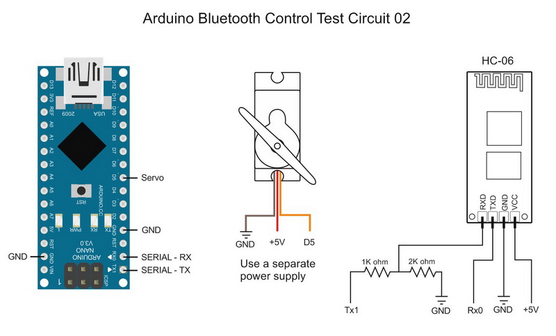
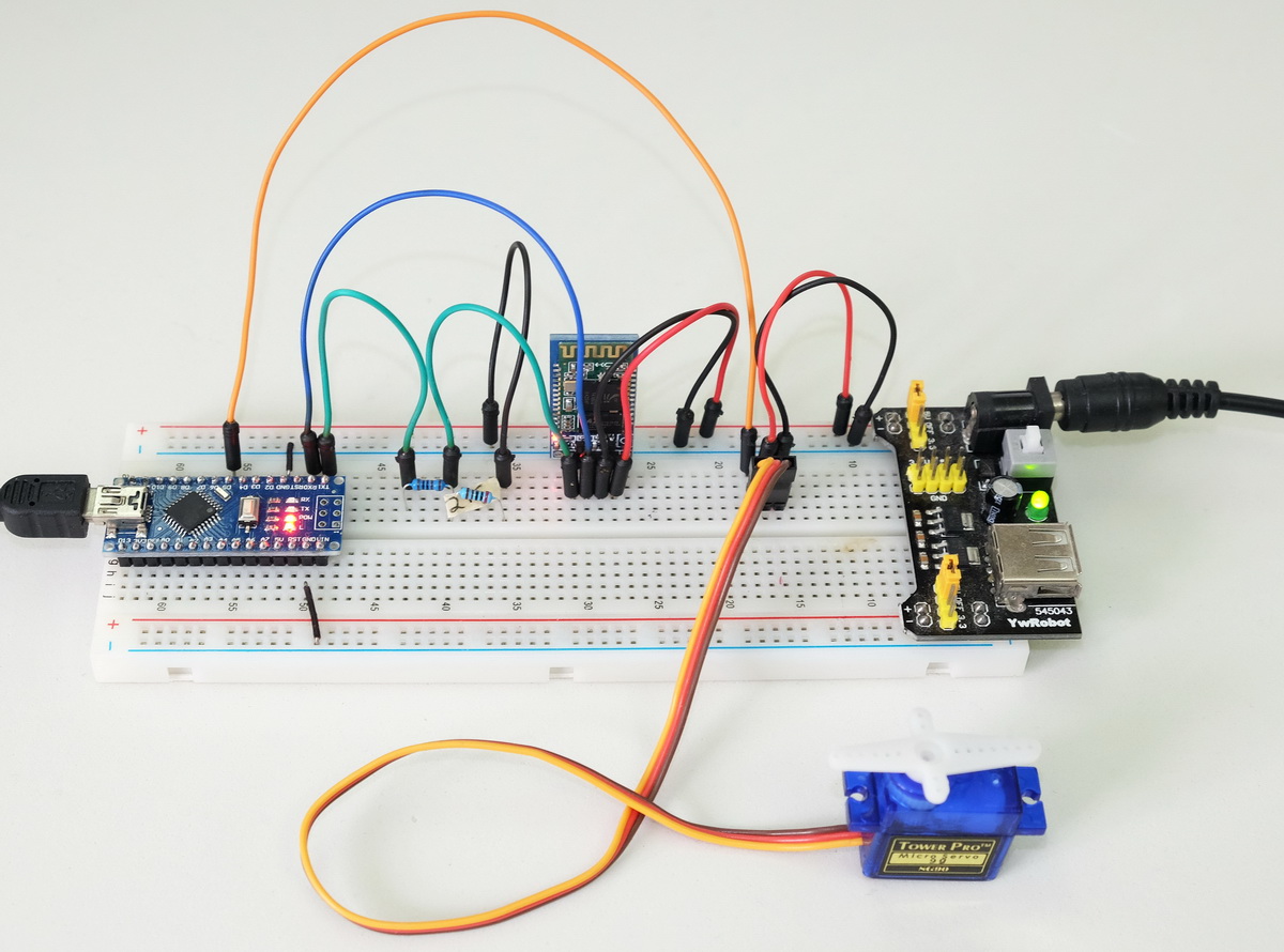
I am using a 5V breadboard power supply to power the servo and the Bluetooth module. The Arduino is powered from the USB, however, once programmed, the Arduino could take power from the breadboard power supply as well. All grounds are connected.
Test Sketch 02. Controlling a servo
The Initialization is just 2 commands:
Serial.print("<P05000170000>"); // Initialize pin D5 for PWM. min=0, max=170, start val=0 Serial.print("<ND05Servo Pos>"); // Set the name for D5 to Servo Pos |
Initialize pin D5 as PWN. Min=0, max=170. Set the pin description to “ServoPos”.
Remember to set the number of commands count to 2:
Serial.print("<C2>"); // number of commands not including itself. |
Main Functions
Since I am only controlling a servo all we need to do it check to see if we have new commands and if we do move the servo.
recvWithStartEndMarkers() – this checks serial in and takes any data that is between the start and end markers (< and >) and places it in to the global variable receivedChars. Any data not within the markers is ignored.
processCommand() – this checks receivedChars and if it is a PWM command we move the servo accordingly. The PWN command has a 3 digit value in ascii format, for example “123”, and this is converted to a numeric value.
byte pin = ((receivedChars[1]-48) *10 ) + receivedChars[2]-48; // PWM pin if ( receivedChars[0] == 'P') { // convert the ascii value to a numeric value byte val = ((receivedChars[3]-48) *100 ) + ((receivedChars[4]-48) * 10) + (receivedChars[5]-48) ; myservo.write(val); } |
Sketch
Because this example uses the hardware serial we cannot upload the sketch while the Arduino is connected to the RX and TX pins. Remove the connections, upload the sketch, and then redo the connections.
/* * Sketch: ArduinoSketch_ArduinoBluetoothControl_example002b_ServoControl * By Martyn Currey * 14.11.2015 * Written in Arduino IDE 1.6.3 * * Requires the Arduino Bluetooth Control Android App. * * See https://www.martyncurrey.com/arduino-bluetooth-control/ * * Control the position of a servo motor * Uses hardware serial to talk to the Bluetooth module * Software serial conflicts with the Servo library * * The example uses the following pins * TX1 - hardware serial TX * RX0 - hardware serial RX * D5 - servo * * It is recommended not to power the servo from the Arduino. * */ #include <Servo.h> Servo myservo; // create a servo object char rc = ' '; const byte maxDataLength = 20; char receivedChars[21] ; boolean newData = false; void setup() { myservo.attach(5); myservo.write(0); // Use the LED on pin 13 to show status // Flashing means sending initialization commands and waiting for a reply // On means the Android app has replied correctly pinMode(13, OUTPUT); digitalWrite(13,LOW); // open serial connection to the bluetooth module Serial.begin(9600); while (!Serial); // Send initialization commands and the wait for an "OK" boolean LEDisON = false; boolean done = false; byte count = 0; boolean sendInitCodes = true; newData = false; int refreshRate = 250; unsigned long startTime = millis(); while (!done) { // This bit flashes the LED on pin 13. if ( millis() - startTime > refreshRate) { startTime = millis(); if (LEDisON) { LEDisON = false; digitalWrite(13,LOW); } else { LEDisON = true; digitalWrite(13,HIGH); } count++; // if reply is not received within 3 seconds resend the commands if (count==12) { count = 0; sendInitCodes = true; } } // Keep sending the initialization commands until the "OK" reply is received. if (sendInitCodes == true) { sendInitCodes = false; Serial.print("<START>"); // Start marker Serial.print("<P05000170000>"); // Initialize pin D5 for PWM. min=0, max=170, start val=0 Serial.print("<ND05Servo Pos>"); // Set the name for D5 to Servo Pos Serial.print("<C2>"); // number of commands not including itself. Serial.print("<END>"); // End marker } recvWithStartEndMarkers(); // check for new data from the Bluetooth module if (newData) { // The Android app receives the commands and sends an "OK" back. if ( (receivedChars[0] == 'O') & (receivedChars[1] == 'K') ) { done = true; } else {newData = false; } } } // while (!done) // Turn on the built in LED to show the app has received the initialization codes digitalWrite(13,HIGH); newData = false; receivedChars[0] = '\0'; } // void setup() void loop() { recvWithStartEndMarkers(); // check to see if we have received any new commands if (newData) { processCommand(); } // if we have a new command set the Arduino pin accordingly delay(5); } /* **************************************** * Function processCommand * parses data commands contained in receivedChars[] * receivedChars[] has not been checked for errors * * Passed: * * Returns * * Global: * receivedChars[] * newData * * Sets/Changes: * newData * */ void processCommand() { newData = false; byte pin = ((receivedChars[1]-48) *10 ) + receivedChars[2]-48; // PWM pin if ( receivedChars[0] == 'P') { // convert the ascii value to a numeric value byte val = ((receivedChars[3]-48) *100 ) + ((receivedChars[4]-48) * 10) + (receivedChars[5]-48) ; myservo.write(val); } } // function recvWithStartEndMarkers by Robin2 of the Arduino forums // See http://forum.arduino.cc/index.php?topic=288234.0 /* **************************************** * Function recvWithStartEndMarkers * reads serial data and returns the content between a start marker and an end marker. * * Passed: * * Returns: * * Global: * receivedChars[] * newData * * Sets: * newData * receivedChars * */ void recvWithStartEndMarkers() { static boolean recvInProgress = false; static byte ndx = 0; char startMarker = '<'; char endMarker = '>'; if (Serial.available() > 0) { rc = Serial.read(); if (recvInProgress == true) { if (rc != endMarker) { receivedChars[ndx] = rc; ndx++; if (ndx > maxDataLength) { ndx = maxDataLength; } } else { receivedChars[ndx] = '\0'; // terminate the string recvInProgress = false; ndx = 0; newData = true; } } else if (rc == startMarker) { recvInProgress = true; } } } |
Download ArduinoSketch ArduinoBluetoothControl example002b ServoControl
Example 3: 3 LEDs, 1 Push Button Switch. 1 Potentiometer
This is a more complex example that has:
– 3 LEDs.
– push button switch
– potentiometer
It also uses the built in LED on pin D13.
All pins are given a descriptive name using the Name command.
The LEDs are controlled from the app; 2 are on/off and 1 is fade on / fade off.
The state of the push button and the value of the potentiometer are shown in the app.
The button switch can be either HIGH or LOW.
The potentiometer value can be from 0 to 1023.
The LED on pin 13 is used to show the sketch status; blinking means sending initialization commands and waiting for the app to reply. Solid on means initialised and receiving/transmitting pin status data.
Pin D10, D11, and D12 have LEDs. The LEDs on pin D11 and D12 are on/off only. The LED on pin D10 is controlled via a PWM signal and fade in and out.
Pin D6 has a button switch attached. The status of the pin is checked and, if the value has changed, the value is sent to the Android app.
Pin A1 has a potentiometer attached, the pin is checked using analogRead() and the value sent to the Android app.
Test Circuit 03. 3 LEDs, Push Button Switch. Potentiometer
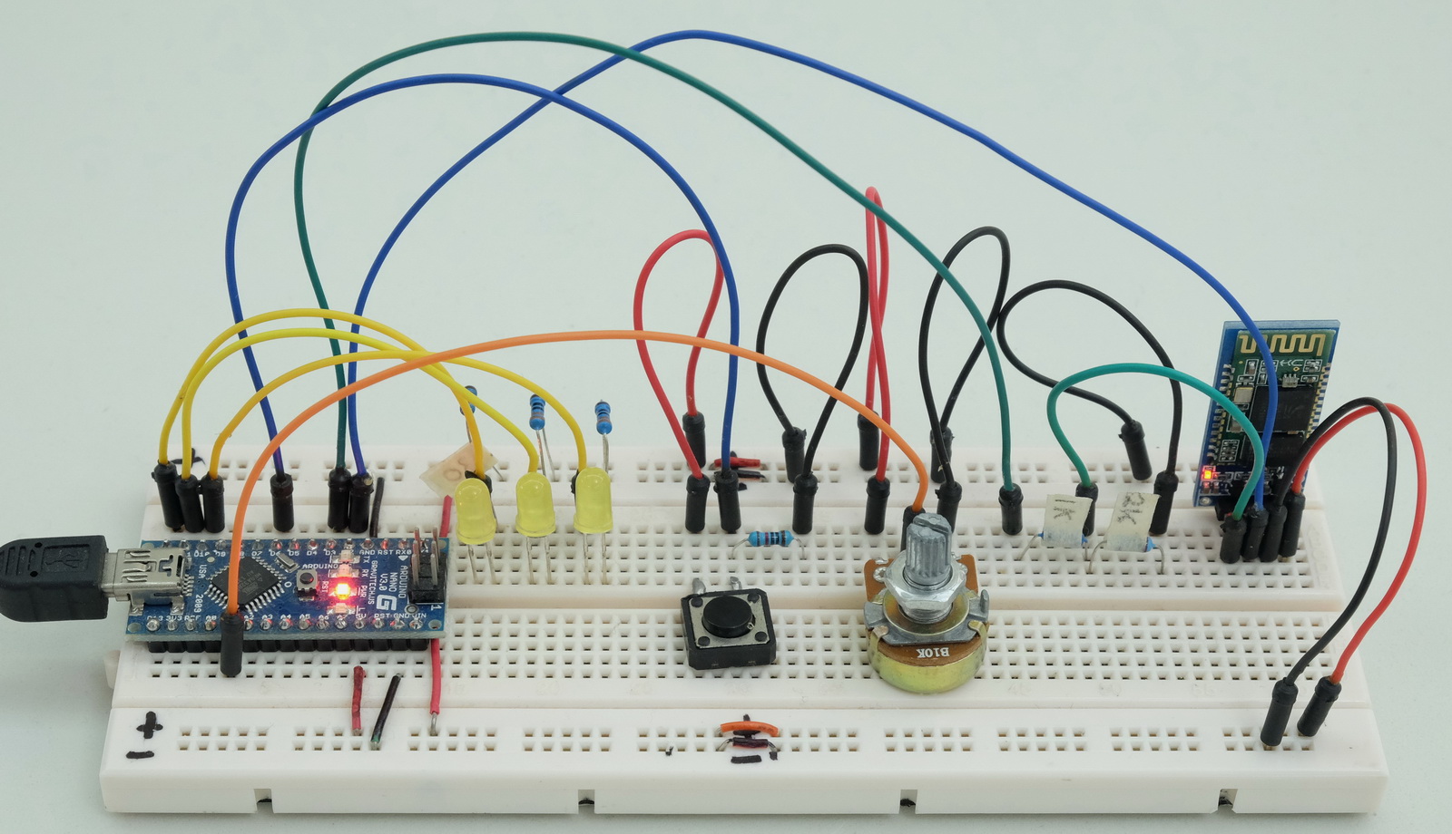
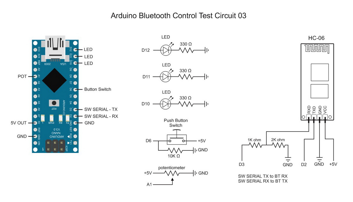
The bluetooth module is a HC-06 set for 9600 baud rate. You can use different baud rates if you wish. Match the baud rate in the sketch with the baud rate of your Bluetooth device. A HC-05 can be used as well.
Test Sketch 03. Controlling 3 LEDs. Monitoring a button switch and a potentiometer
Set the pin function
Set the pins; the LED pins for output and D6 for input.
// set the button switch pin to input pinMode(6, INPUT); // Set the LED pins to output and turn them off. pinMode(12, OUTPUT); // Pin 12 pinMode(11, OUTPUT); // Pin 11 pinMode(10, OUTPUT); // Pin 10 digitalWrite(12,LOW); digitalWrite(11,LOW); digitalWrite(10,LOW); // potPin (A1) does not need initializing //Pin 13 LED is used to show status // Flashing means sending initialization commands and waiting for a reply // On means the Android app has replied correctly pinMode(13, OUTPUT); digitalWrite(13,LOW); |
Initialization commands
Initialize the pins:
BTserial.print("<START>"); // Start marker BTserial.print("<A010000>"); // Initialize analogue pin A01. Start value 0 BTserial.print("<D06IL>"); // Set D6 to input. Start value = LOW BTserial.print("<P10000255000>"); // Initialize D10 for PWN. Start value = 0 BTserial.print("<D11OL>"); // set D11 to output. Start value = LOW BTserial.print("<D12OL>"); // set D12 to output. Start value = LOW BTserial.print("<ND12LED #1>"); // set the pin description for D12 to LED #1 BTserial.print("<ND11LED #2>"); // set the pin description for D11 to LED #2 BTserial.print("<ND10LED Fader>"); // set the pin description for D10 to LED Fader BTserial.print("<ND06BTN Switch>"); // set the pin description for D6 to BTN Switch BTserial.print("<NA01Potentiometer>"); // set the pin description for A1 to Potentiometer. This will be truncated BTserial.print("<C10>"); // number of commands not including itself. BTserial.print("<END>"); // End marker |
Main Functions
checkPins() – this reads the input pins status and if changed sends the value out via software serial.
formatNumber – converts a numeric value to an ascii string
recvWithStartEndMarkers() – this checks the software serial in and takes any data that is between the start and end markers (< and >). Any data not within the markers is ignored. The received data is put in to the global variable receivedChars
processCommand() – this checks the received data and if the pin number matches the pin we are using (D12) it is set HIGH or LOW to turn the LED either on or off.
/* * Sketch: ArduinoSketch_ArduinoBluetoothControl_example003b * By Martyn Currey * 01.07.2015 * Written in Arduino IDE 1.6.3 * * Requires the Arduino Bluetooth Control Android App. * * See https://www.martyncurrey.com/arduino-bluetooth-control/ * * Read pin states / values and send to an Android app over bluetooth * Receive control commands from the Android app * The Android app is initialized by commands sent from the Arduino * * The example uses the following pins * A1 - a potentiometer * D2 - software serial RX * D3 - software serial TX * D6 - button switch (pulled LOW) * D10 - LED * D11 - LED * D12 - LED */ // The Bluetooth module is connected to pin D2 and D3 and uses software serial #include <SoftwareSerial.h> SoftwareSerial BTserial(2,3); // RX | TX // Change DEBUG to true to output debug information to the serial monitor const boolean DEBUG = true; char numberString[10]; // used to hold an ascii representation of a number // [10] allows for 9 digits but in this example I am only using 4 digits char rc = ' '; const byte maxDataLength = 20; char receivedChars[21] ; boolean newData = false; unsigned long startTime = 0; unsigned long refreshRate = 100; // I only send a value if the value has changed. // This means I need to store the old value unsigned int oldPotVal = 0; unsigned int newPotVal = 0; boolean oldButtonSwitchState = false; boolean newButtonSwitchState = false; void setup() { // set the button switch pin to input pinMode(6, INPUT); // Set the LED pins to output and turn them off. pinMode(12, OUTPUT); // Pin 12 pinMode(11, OUTPUT); // Pin 11 pinMode(10, OUTPUT); // Pin 10 digitalWrite(12,LOW); digitalWrite(11,LOW); digitalWrite(10,LOW); // potPin (A1) does not need initializing //Pin 13 LED is used to show status // Flashing means sending initialization commands and waiting for a reply // On means the Android app has replied correctly pinMode(13, OUTPUT); digitalWrite(13,LOW); if (DEBUG) { // open serial communication for debugging Serial.begin(9600); Serial.println("ArduinoSketch_ArduinoBluetoothControl_example003b"); Serial.println(" "); } // open software serial connection to the Bluetooth module BTserial.begin(9600); // Send initialization commands and the wait for an "OK" boolean LEDisON = false; boolean done = false; byte count = 0; boolean sendInitCodes = true; newData = false; refreshRate = 500; startTime = millis(); while (!done) { // This bit flashes the LED on pin 13. if ( millis()-startTime > refreshRate) { startTime = millis(); if (LEDisON) { LEDisON = false; digitalWrite(13,LOW); } else { LEDisON = true; digitalWrite(13,HIGH); } count++; // if reply is not received within 3 seconds resend the commands if (count==6) { count = 0; sendInitCodes = true; } } // Keep sending the initialization commands until the "OK" reply is received. if (sendInitCodes == true) { sendInitCodes = false; dumpBTserialBuffer(); // not really required but it makes me feel better :-) BTserial.print("<START>"); // Start marker BTserial.print("<A010000>"); // Initialize analogue pin A01. Start value 0 BTserial.print("<D06IL>"); // Set D6 to input. Start value = LOW BTserial.print("<P10000255000>"); // Initialize D10 for PWN. Start value = 0 BTserial.print("<D11OL>"); // set D11 to output. Start value = LOW BTserial.print("<D12OL>"); // set D12 to output. Start value = LOW BTserial.print("<ND12LED #1>"); // set the pin description for D12 to LED #1 BTserial.print("<ND11LED #2>"); // set the pin description for D11 to LED #2 BTserial.print("<ND10LED Fader>"); // set the pin description for D10 to LED Fader BTserial.print("<ND06BTN Switch>"); // set the pin description for D6 to BTN Switch BTserial.print("<NA01Potentiometer>"); // set the pin description for A1 to Potentiometer. This will be truncated BTserial.print("<C10>"); // number of commands not including itself. BTserial.print("<END>"); // End marker if (DEBUG) { Serial.println("Sent init commands. Waiting for receipt"); } } recvWithStartEndMarkers(); // check for new data from the Bluetooth module if (newData) { // The Android app receives the commands and sends an "OK" back. if ( (receivedChars[0] == 'O') & (receivedChars[1] == 'K') ) { done = true; } else {newData = false; } if (DEBUG) { Serial.print("receivedChars = "); Serial.println( receivedChars ); } } } // while (!done) // Turn on the built in LED to show the app has received the initialization codes digitalWrite(13,HIGH); if (DEBUG) { Serial.println("OK received from the app"); } // refeshRate is the frequency to check the input pins refreshRate = 100; } // void setup() void loop() { if ( millis()-refreshRate > startTime) { startTime = millis(); checkPins(); // read the pin values and if the values have changed send the new values to the Android app } recvWithStartEndMarkers(); // check to see if we have received any new commands if (newData) { processCommand(); } // if we have a new command set the Arduino pin accordingly } /* **************************************** * dumpBTserialBuffer * removes data from the software serial buffer * * passed: * * global: * * Returns: * * Sets: * */ void dumpBTserialBuffer() { while(BTserial.available() > 0) { char t = BTserial.read(); } } /* **************************************** * Function processCommand * parses data commands contained in receivedChars[] * receivedChars[] has not been checked for errors * * passed: * * global: * receivedChars[] * newData * * Returns: * * Sets: * */ void processCommand() { newData = false; byte pin = ((receivedChars[1]-48) *10 ) + receivedChars[2]-48; // digital pin if ( receivedChars[0] == 'D') { if ( receivedChars[3] == 'H') { digitalWrite(pin,HIGH); } if ( receivedChars[3] == 'L') { digitalWrite(pin,LOW); } if (DEBUG) { Serial.print("Digital pin command = "); Serial.println(receivedChars); } } // PWM pin if ( receivedChars[0] == 'P') { byte val = ((receivedChars[3]-48) *100 ) + ((receivedChars[4]-48) * 10) + (receivedChars[5]-48) ; analogWrite(pin, val); if (DEBUG) { Serial.print("PWN command = "); Serial.println(receivedChars); } } } /* **************************************** * Function checkPins * Checks the values of the deignated pins and if the value has changed sends ascii codes to software serial * * passed: * * global: * newPotVal * oldPotVal * potPin * newButtonSwitchState * oldButtonSwitchState * buttonSwitchPin * numberString * * Returns: * * Sets: * */ void checkPins() { // Check the value on analogue pin A1 newPotVal = analogRead(A1); //The pot I am using jitters +/- 1 so I only using changes of 2 or more. if ( abs(newPotVal-oldPotVal) > 1) { oldPotVal = newPotVal; formatNumber( newPotVal, 4); BTserial.print("[A01"); BTserial.print(numberString); BTserial.print("]"); if (DEBUG) { Serial.print("[A01"); Serial.print(numberString); Serial.println("]"); } } // Check the state of pin 6 - the button switch. newButtonSwitchState = digitalRead(6); if (newButtonSwitchState != oldButtonSwitchState) { oldButtonSwitchState = newButtonSwitchState; if (oldButtonSwitchState == true) { if (DEBUG) { Serial.println("[D06H]"); } BTserial.print("[D06H]"); } else { if (DEBUG) { Serial.println("[D06L]"); } BTserial.print("[D06L]"); } } } /* **************************************** * Function formatNumber * formats a number in to a string and copies it to the global char array numberString * pads the start of the string with '0' characters * * passed: * number = the integer to convert to a string * digits = the number of digits to use * * global: * numberString * * Returns: * * Sets: * numberString * */ void formatNumber( unsigned int number, byte digits) { char tempString[10] = "\0"; strcpy(numberString, tempString); // convert an integer into a acsii string base 10 itoa (number, tempString, 10); // create a string of '0' characters to pad the number byte numZeros = digits - strlen(tempString) ; if (numZeros > 0) { for (int i=1; i <= numZeros; i++) { strcat(numberString,"0"); } } strcat(numberString,tempString); } // function recvWithStartEndMarkers by Robin2 of the Arduino forums // See http://forum.arduino.cc/index.php?topic=288234.0 /* **************************************** * Function recvWithStartEndMarkers * reads serial data and returns the content between a start marker and an end marker. * * passed: * * global: * receivedChars[] * newData * * Returns: * * Sets: * newData * receivedChars * */ void recvWithStartEndMarkers() { static boolean recvInProgress = false; static byte ndx = 0; char startMarker = '<'; char endMarker = '>'; if (BTserial.available() > 0) { rc = BTserial.read(); if (recvInProgress == true) { if (rc != endMarker) { receivedChars[ndx] = rc; ndx++; if (ndx > maxDataLength) { ndx = maxDataLength; } } else { receivedChars[ndx] = '\0'; // terminate the string recvInProgress = false; ndx = 0; newData = true; } } else if (rc == startMarker) { recvInProgress = true; } } } |
Download ArduinoSketch ArduinoBluetoothControl example003b
Example 04. Single Analogue Sensor (Potentiometer)
This is a basic example of using a single analogue sensor. For this example I am using a potentiometer but any other analogue sensor can be used. The potentiometer is connected to A1,
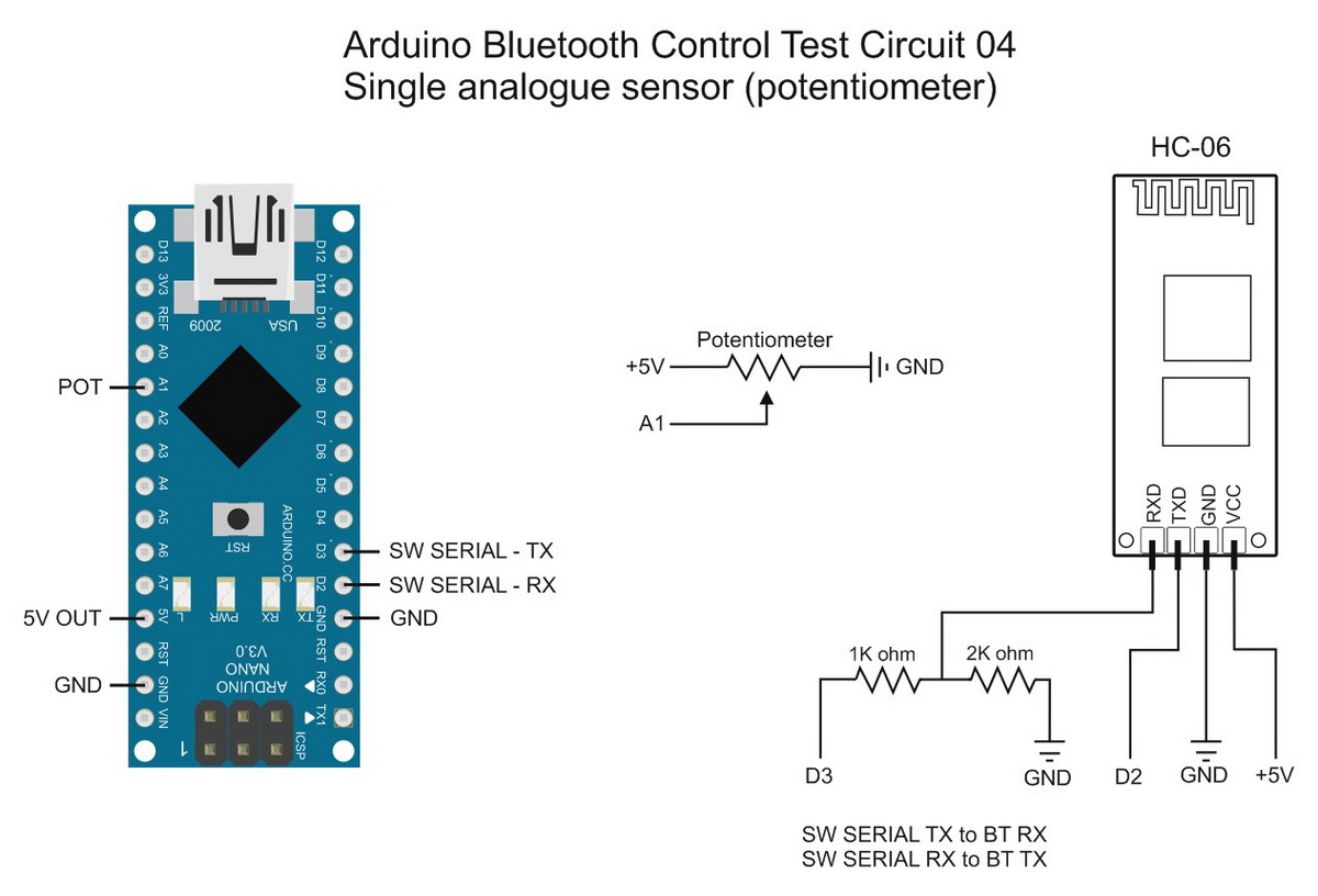
Test Sketch 04. Monitoring a a potentiometer
All this sketch does is read analogue pin A1 and send the value to the Android app. We are not receiving any data from the app and so we do not need to check.
Initialization commands
Set pin A1 for analogue and rename to “Potentiometer”
BTserial.print("<START>"); // Start marker BTserial.print("<A010000>"); // Initialize analogue pin A01. Start value 0 BTserial.print("<NA01Potentiometer>"); // set the pin description for A1 to Potentiometer. This will be truncated BTserial.print("<C2>"); // number of commands not including itself. BTserial.print("<END>"); // End marker |
/* * Sketch: ArduinoSketch_ArduinoBluetoothControl_example004b_Single_analogue_sensor * By Martyn Currey * 28.11.2015 * Written in Arduino IDE 1.6.3 * * Requires the Arduino Bluetooth Control Android App. * * See https://www.martyncurrey.com/arduino-bluetooth-control/ * * Read pin states / values and send to an Android app over bluetooth * The Android app is initialized by commands sent from the Arduino * * The example uses the following pins * A1 - potentiometer */ // Change DEBUG to true to output debug information to the serial monitor const boolean DEBUG = true; // The Bluetooth module is connected to pin D2 and D3 and uses software serial #include <SoftwareSerial.h> SoftwareSerial BTserial(2,3); // RX | TX char numberString[10]; char rc = ' '; const byte maxDataLength = 20; char receivedChars[21] ; boolean newData = false; unsigned long startTime = 0; unsigned long refreshRate = 2500; unsigned int oldAnalogueVal = 0; unsigned int newAnalogueVal = 0; void setup() { // A1 does not need initializing if (DEBUG) { // open serial communication for debugging Serial.begin(9600); while (!Serial) {;} Serial.println("ArduinoSketch_ArduinoBluetoothControl_example004b_Single_analogue_sensor"); } // open software serial connection to the Bluetooth module BTserial.begin(9600); if (DEBUG) { Serial.println("BTserial started at 9600"); } newData = false; refreshRate = 3000; // how often to send the init codes boolean done = false; startTime = millis(); while (!done) { if ( millis()-startTime > refreshRate) { startTime = millis(); BTserial.print("<START>"); // Start marker BTserial.print("<A010000>"); // Initialize analogue pin A01. Start value 0 BTserial.print("<NA01Potentiometer>"); // set the pin description for A1 to Potentiometer. This may be truncated BTserial.print("<C2>"); // number of commands not including itself. BTserial.print("<END>"); // End marker if (DEBUG) { Serial.println("Sent init commands. Waiting for receipt"); } } recvWithStartEndMarkers(); // check for new data from the Bluetooth module if (newData) { if ( (receivedChars[0] == 'O') & (receivedChars[1] == 'K') ) { done = true; } else {newData = false; } if (DEBUG) { Serial.print("receivedChars = "); Serial.println( receivedChars ); } } } // while (!done) if (DEBUG) { Serial.println("OK received from the app"); } // refeshRate is the frequency to check the input pin refreshRate = 500; startTime = millis(); } // void setup() void loop() { if ( millis()-refreshRate > startTime) { startTime = millis(); // Check the value on analogue pin A1 newAnalogueVal = analogRead(A1); if ( newAnalogueVal != oldAnalogueVal ) { oldAnalogueVal = newAnalogueVal; formatNumber( newAnalogueVal, 4); BTserial.print("[A01"); BTserial.print(numberString); BTserial.print("]"); if (DEBUG) { Serial.print("[A01"); Serial.print(numberString); Serial.println("]"); } } } } // loop() void formatNumber( unsigned int number, byte digits) { char tempString[10] = "\0"; strcpy(numberString, tempString); // convert an integer into a acsii string base 10 itoa (number, tempString, 10); // create a string of '0' characters to pad the number byte numZeros = digits - strlen(tempString) ; if (numZeros > 0) { for (int i=1; i <= numZeros; i++) { strcat(numberString,"0"); } } strcat(numberString,tempString); } // function recvWithStartEndMarkers by Robin2 of the Arduino forums // See http://forum.arduino.cc/index.php?topic=288234.0 void recvWithStartEndMarkers() { static boolean recvInProgress = false; static byte ndx = 0; char startMarker = '<'; char endMarker = '>'; if (BTserial.available() > 0) { rc = BTserial.read(); if (recvInProgress == true) { if (rc != endMarker) { receivedChars[ndx] = rc; ndx++; if (ndx > maxDataLength) { ndx = maxDataLength; } } else { receivedChars[ndx] = '\0'; // terminate the string recvInProgress = false; ndx = 0; newData = true; } } else if (rc == startMarker) { recvInProgress = true; } } } |
Download ArduinoSketch ArduinoBluetoothControl example004
Example 05. Using RESET
In version 3 of the app I added a <RESET> command. Here is a brief example on how to use it to have the Arduino automatically resend the initiazation commands when it detects the reset.
I am using the same circuit as example 4 – a single analogue sensor (potentiometer)
The main difference in the sketch is that the part that sends the initization commands has been moved to its own function. The means we can call it at anytime.
The varaible initialized is used to show whether or not we have sent the init commands and received a reply. When initialized is TRUE we know the Arduino has connected to the app and we can start to send and/or receive pin data.
We we receive the <RESET> command we simply set initialized to FALSE.
/* * Sketch: ArduinoSketch_ArduinoBluetoothControl_RESET * By Martyn Currey * 13.02.2016 * Written in Arduino IDE 1.6.3 * * Requires the Arduino Bluetooth Control Android App. * * See https://www.martyncurrey.com/arduino-bluetooth-control/ * * Read pin states / values and sends to an Android app over bluetooth * Receive control commands from the Android app * The Android app is initialized by commands sent from the Arduino * * The example uses the following pins * A1 - a potentiometer * D2 - software serial RX * D3 - software serial TX */ // The Bluetooth module is connected to pin D2 and D3 and uses software serial #include <SoftwareSerial.h> SoftwareSerial BTserial(2,3); // RX | TX // Change DEBUG to true to output debug information to the serial monitor const boolean DEBUG = true; char numberString[10]; // used to hold an ascii representation of a number // [10] allows for 9 digits but in this example I am only using 4 digits char rc = ' '; const byte maxDataLength = 20; char receivedChars[21] ; boolean newData = false; unsigned long startTime = 0; unsigned long refreshRate = 100; // I only send a value if the value of the sensor has changed. // This means I need to store the old value so I can compare. unsigned int oldPotVal = 0; unsigned int newPotVal = 0; boolean initialized = false; void setup() { // potPin (A1) does not need initializing //Pin 13 LED is used to show status // Flashing means sending initialization commands and waiting for a reply // On means the Android app has replied correctly pinMode(13, OUTPUT); digitalWrite(13,LOW); if (DEBUG) { // open serial communication for debugging Serial.begin(9600); Serial.println(__FILE__); Serial.println(__DATE__); Serial.println(" "); } BTserial.begin(9600); // open software serial connection to the Bluetooth module refreshRate = 100; // refeshRate is the frequency to check the input pins } // void setup() void loop() { if (!initialized) { sendInitCommands(); // send the init commands and wait for a reply. } else { if ( millis()-refreshRate > startTime) { startTime = millis(); checkPins(); // read the pin values and if the values have changed send the new values to the Android app } recvWithStartEndMarkers(); // check to see if we have received any new commands if (newData) { processCommand(); } // if we have a new command do something about it } } /* **************************************** * Function sendInitCommands * Sends initialization commands and then waits for a "OK" reply. * * passed: * * global: * receivedChars[] * newData * * Returns: * * Sets: * */ void sendInitCommands() { // Send initialization commands and the wait for an "OK" boolean LEDisON = false; boolean done = false; byte count = 0; boolean sendInitCodes = true; newData = false; long unsigned startTime = millis(); while (!done) { // This bit flashes the LED on pin 13. if ( millis()-startTime > 500 ) { startTime = millis(); if (LEDisON) { LEDisON = false; digitalWrite(13,LOW); } else { LEDisON = true; digitalWrite(13,HIGH); } count++; // if reply is not received within 3 seconds resend the commands if (count>=6) { count = 0; sendInitCodes = true; } } // Keep sending the initialization commands until the "OK" reply is received. if (sendInitCodes == true) { dumpBTserialBuffer(); // not really required but it makes me feel better :-) BTserial.print("<START>"); // Start marker BTserial.print("<A010000>"); // Initialize analogue pin A01. Start value 0000 BTserial.print("<NA01Potentiometer>"); // set the pin description for A1 to Potentiometer. This will be truncated BTserial.print("<C2>"); // number of commands not including itself BTserial.print("<END>"); // End marker sendInitCodes = false; if (DEBUG) { Serial.println("Sent init commands. Waiting for reply"); } } recvWithStartEndMarkers(); // check for new data from the Bluetooth module if (newData) { // The Android app receives the commands and sends an "OK" back. if (strcmp ("OK",receivedChars) == 0) { done = true; } else { newData = false; } if (DEBUG) { Serial.print("receivedChars = "); Serial.println( receivedChars ); } } } // while (!done) initialized = true; // Turn on the built in LED to show the app has received the initialization codes digitalWrite(13,HIGH); if (DEBUG) { Serial.println("OK received from the app"); } } /* **************************************** * dumpBTserialBuffer * removes data from the software serial buffer * * passed: * * global: * * Returns: * * Sets: * */ void dumpBTserialBuffer() { while(BTserial.available() > 0) { char t = BTserial.read(); } } /* **************************************** * Function processCommand * parses data commands contained in receivedChars[] * receivedChars[] has not been checked for errors * * passed: * * global: * receivedChars[] * newData * * Returns: * * Sets: * */ void processCommand() { newData = false; if (strcmp ("RESET",receivedChars) == 0) { initialized = false; } if (strcmp ("DISCONECT",receivedChars) == 0) { initialized = false; } if (DEBUG) { Serial.print("Recieved data = "); Serial.println(receivedChars); } } /* **************************************** * Function checkPins * Checks the values of the deignated pins and if the value has changed sends ascii codes to software serial * * passed: * * global: * newPotVal * oldPotVal * potPin * newButtonSwitchState * oldButtonSwitchState * buttonSwitchPin * numberString * * Returns: * * Sets: * */ void checkPins() { // Check the value on analogue pin A1 newPotVal = analogRead(A1); //The pot I am using jitters +/- 1 so I only using changes of 2 or more. if ( abs(newPotVal-oldPotVal) > 1) { oldPotVal = newPotVal; formatNumber( newPotVal, 4); BTserial.print("[A01"); BTserial.print(numberString); BTserial.print("]"); if (DEBUG) { Serial.print("[A01"); Serial.print(numberString); Serial.println("]"); } } } /* **************************************** * Function formatNumber * formats a number in to a string and copies it to the global char array numberString * pads the start of the string with '0' characters * * passed: * number = the integer to convert to a string * digits = the number of digits to use * * global: * numberString * * Returns: * * Sets: * numberString * */ void formatNumber( unsigned int number, byte digits) { char tempString[10] = "\0"; strcpy(numberString, tempString); // convert an integer into a acsii string base 10 itoa (number, tempString, 10); // create a string of '0' characters to pad the number byte numZeros = digits - strlen(tempString) ; if (numZeros > 0) { for (int i=1; i <= numZeros; i++) { strcat(numberString,"0"); } } strcat(numberString,tempString); } // function recvWithStartEndMarkers by Robin2 of the Arduino forums // See http://forum.arduino.cc/index.php?topic=288234.0 /* **************************************** * Function recvWithStartEndMarkers * reads serial data and returns the content between a start marker and an end marker. * * passed: * * global: * receivedChars[] * newData * * Returns: * * Sets: * newData * receivedChars * */ void recvWithStartEndMarkers() { static boolean recvInProgress = false; static byte ndx = 0; char startMarker = '<'; char endMarker = '>'; if (BTserial.available() > 0) { rc = BTserial.read(); if (recvInProgress == true) { if (rc != endMarker) { if (ndx < maxDataLength) { receivedChars[ndx] = rc; ndx++; } } else { receivedChars[ndx] = '\0'; // terminate the string recvInProgress = false; ndx = 0; newData = true; } } else if (rc == startMarker) { recvInProgress = true; } } } |
Download ArduinoSketch_ArduinoBluetoothControl_RESET
Downloads
Download ArduinoSketch_ArduinoBluetoothControl_example001_single_LED_b
Download ArduinoSketch ArduinoBluetoothControl example002b ServoControl
Download ArduinoSketch ArduinoBluetoothControl example003b
Download ArduinoSketch ArduinoBluetoothControl example004
Download ArduinoSketch_ArduinoBluetoothControl_RESET
App Source Code / aia File
I had intended to clean up the code used in the app before posting the source code but, life got in the way and I never managed to do it, and the longer I left it, the harder it became to get back to.
The code works fine but it is not particularly efficient. There are 2 very similar code blocks, one handling the initiation commands and the other handling the data commands. These could very easily be merged in to one.
If you use the code to make something more interesting, please let me know.
First of all: thanks for sharing! Nice.
When I was working on an app created with MIT App Inventor 2 I came across your post.
I have created a moodlight with an APA102 LED string with configurable settings in EEPROM on the Arduino.
What I wanted to do is let the app send a command to retrieve the settings, the Arduino will then return key=value pairs, the same pairs that can be sent by the app.
So if the Arduino needs to refresh the settings on the app it can send the values.
Regards,
Eric
So, would it be an added feature to let the Arduino set the values on the app?
This is very possible but beyond the scope of the above.
My solution would be to implement the processCommand() and recvWithStartEndMarkers() functions in the Android app, use start and end markers, and then process commands in app the same way as in the Arduino sketch.
Martyn,
I am from the MIT2 forum.
I changed the 003 sample.
As said I declared ValueOut1 as integer.
Changed
void checkPins()
{
ValueOut1 = 1023;
// Check the value on analogue pin A1
//newPotVal = analogRead(A1); //original code
newPotVal = ValueOut1;
//The pot I am using jitters +/- 1 so I only using changes of 2 or more.
if ( abs(newPotVal – oldPotVal) > 0)
{
oldPotVal = newPotVal;
formatNumber( newPotVal, 4);
BTserial.print(“[A01”);
BTserial.print(numberString);
BTserial.print(“]”);
if (DEBUG) {
Serial.print(“[A01”);
Serial.print(numberString);
Serial.println(“]”);
}
}
What I in the serial monitor see is:
ArduinoSketch_ArduinoBluetoothControl_example003
Sent init commands. Waiting for receipt
Sent init commands. Waiting for receipt
Sent init commands. Waiting for receipt
Sent init commands. Waiting for receipt
Sent init commands. Waiting for receipt
Sent init commands. Waiting for receipt
Sent init commands. Waiting for receipt
receivedChars = DISCONECT
Sent init commands. Waiting for receipt
Sent init commands. Waiting for receipt
Sent init commands. Waiting for receipt
receivedChars = OK
OK received from the app
[A011023]
it is only one value in the last line and there is no update but that is correct.
As the value is not changing as it is a static one the serial monitor does not show them line by line.
But the ABC app does show 0000 in the datafield and not 1023.
What goes wrong?
Your help is appricaited to get things going.
Paco
Hi Paco,
It looks like the Bluetooth module is disconnecting. See “receivedChars = DISCONECT”. What BT module are you using?
0000 is the default value. You can change this to something else in the initialization command, try <A011111>.
I will try to add a sketch later this weekend showing the bare minimum required for an analogue sensor.
.
EDIT
Just added example 04. A basic example for monitoring a single analogue pin.
I have noticed that sometimes the Arduino is not quite ready when the app sends the acknowledgement signal and the signal gets corrupted and not recognised. When this happens the sketch will keep sending the init codes but the app has already displayed the pin but the pin value will not change. If this happens try using the RESET button on the Bluetooth tab.
06.12.2015: figured this out. I was checking the elapsed time incorrectly. I was using “if ( millis()-refreshRate > startTime)” instead of “if ( millis()-startTime > refreshRate)”.
I have updated the above sketches.
Hello Martyn,
Sample 04 works fine.
When I change the value to 1023 it is nicely mentioned in the ABC app.
I just blew my Nano so have to wait for new supply to test more then one serial data value. Let you know.
Paco
Hello Martyn,
Finally I found this great app for controlling arduino :) I think this is the best app. Thank you Martyn you are very talented.
I am working on a project and I need some help to write the code and using the Bluetooth module for controlling.
The main idea is simple: Controlling a Dc motor (6-9v geared motor) with Arduino Uno + L298 H bridge + bluetooth module
It’s a basic controlling of the DC motor, these are the commands what I need:
– loop start switch: which starts the motor, and the motor continuously running until the stop button is pressed
– program start switch: which starts a program of running the motor for example 10 sec. and after 10 sec. stops.
– direction switch: which controls the direction of the motor
– stop switch: stops the motor
– Fader: Speed controller of the motor
Can I do this with bluetooth and your ABC app?
Can you help me writing the code? Any help is well appreciated. :)
Thank you!
Peter
You can do this by re-purposing the commands and ignoring the pin numbers but it would not be an ideal solution.
On the Arduino side you can perform any function you like based on the commands received. For example D02H does not have to mean bring pin D2 HIGH. It could mean start a motor on pin 10. It is up to you.
some examples:
D2 – set up as a start stop switch (LOW = off. HIGH = on)
D3 – use for direction (HIGH left, LOW right) ( you could even use a slider (min1 max3. 1=left, 2=stop, 3=right)
D4 – set program. HIGH = start program (start the motor for 10 seconds). When the program has completed send a commands from the Arduino to change the status to LOW.
D5 – slider to control the motor speed.
Another example. I use a slider (min=1 max=4) to determine 1 of 4 actions rather than 4 separate buttons.
I am now travelling until after the new year so cannot offer more help and all I can suggest is experiment.
Hello Martyn,
I couldn’t figured out how to write the code for the above application. I have all the parts, the Bluetooth works very well, and the demo codes too :)
Can you help me please writing the code for the above application?
How can I start and, how to send the commands to the H298N bridge for controling the dc motor?
Thank you for your help!
Hi Peter,
assuming you have 2 directions; left and right, I would use a slider. Min value 1, max value 3. Initial value 2.
Then in the Arduino sketch a 1 would mean left, 3 would mean right and 2 would mean off/stop. This would work for a simply on/off system but would not offer any speed control.
If you wanted speed control you could use a slider with a larger scale, for example 0-100 and then use 0-49 for left, 51-100 for right and 50 as off. 1 would be fastest left and 100 would be fastest right.
Using buttons is not the best solution because you can have both buttons HIGH at the same time and of course you cannot have a motor turning left and right at the same time.
ABC is not really the best solution for your project. It was designed as a simply way to control or monitor Arduino pins. I am now working on a different controller which is based on functions rather than pins but it is likely to be a while before it is ready.
Your project has inspired me to add motor control and toggle buttons. Something I had not considered before.
If you fancy having a play with app inventor have a look at https://www.martyncurrey.com/arduinobtcontrol/ which includes a navigation keypad that may be better suited for your project. The aia file is available for download.
Thank you Martin,
Now I have a working controller :), finally I’ve figured out. So I have a button for Left turn and for Right turn. If both are LOW the motor is stopped. If I change HIGH or the left or the right button the motor tuns left or right. And I have a slider for speed control.
One more question. How can I assign a slider to control LOW HIGH parameters and not PWM? Can you help me with a sample code.
And what do you think what is wrong with the code? when I press the reset in the app, doesn’t make the reinitialization. the app says waiting for initialization commands. I need to press the reset button on arduino to initialize.
thank you.
————————————–
Hi Peter,
it is up to you how you handle the data the Arduino receives from the app. For example the slider data <P10000> and <P10001> can be used as a switch. If the value = 000 set a pin to LOW, if it is 001 set a pin HIGH. Or even display a message on an LCD, or flash an LED.
The reset button restarts the app and so the initialization commands need to be resent.
Is it possible after pressing the reset button in the app, the initialization codes to be resent automatically?
—————————————
Not at this time.
The reset button was implemented so that when the Arduino is restarted you do not need to restart the app, just use the reset button.
Martyn
Thank you Martyn,
I will try,
Have a nice travel!
First of all your project is nice !
Can you please add the .aia file for app inventor here, so that we can see how the app work ?
Thanks.
Yes it s really awesome
I would like too the aia
To see how it s done and to translate in my language
Thanks a lot
Display graph with canvas will ne great
I ve seen tuto on accéléromèter who doing it
Is it possible to digital read data from a sensor. I have a dht 21 temp and humidity sensor and I can’t figured out how to see data on phone. Data is transmited on a single digital pin, out pin(D20 for example). I will apreciate very much if you can help me.
I would suggest breaking the problem down in to small tasks. Get the sensors working first with output to the serial monitor. Once you are happy with this then add the app. Use test sketch 4 as a starting point.
hello sir
can you give me an arduino code for dimming a led.
i need it for my project.
tnx
jaime
Have a look at Example 3 above. One of the LEDs in the example is controlled by a slider.
thanks sir Martyn
it really helps me in my projects:D
great examples!
hello sir
can you give me sample slider blocks in app inventor?
Hi Martyn,
First of all thank you very very much for sharing this awesome knowledge with us.
It helped me to get most of my answers.
Well i am unable to write a code for my arduino to control my 8-channel relay board without any errors.
kindly help me with this,i am using your app.
Thank You!
To get started simply extend Example 01.
To add extra pins there are 3 things to extend; 2 inside the setup() function and 1 inside the processCommand() function.
Inside setup() –
Define the pins at
// Set the LED pin to output
pinMode(12, OUTPUT);
digitalWrite(12,LOW);
add extra pins here
pinMode(11, OUTPUT);
digitalWrite(11,LOW);
Initialization commands at
BTserial.print(“<D12OL>”);
add extra pins here
BTserial.print(“<D11OL>”);
(remember to update the <Cn> command)
Inside the processCommand() function-
// does the pin data command start with a “D”
if ( receivedChars[0] == ‘D’)
{
byte pin = ((receivedChars[1]-48) *10 ) + receivedChars[2]-48; // get the pin number
if (pin == 12)
{
if ( receivedChars[3] == ‘H’) { digitalWrite(pin,HIGH); }
if ( receivedChars[3] == ‘L’) { digitalWrite(pin,LOW); }
}
// add extra pins here
if (pin==11)
{
}
}
Does the ABC work with a BlueSMiRF RN-41 module & Arduino Mega?
If not, is their a way to adapt it to?
The BlueSMiRF RN-41 device is Bluetooth V2.0 and although I haven’t tried (I don’t own one) it should work. Please let me know how you get on.
thank you for sharing! very interesting.
i did want to have a closer look to your software, but unfortunately i wasn’t able to connect to arduino. i am using hc05 and my smartphone is “nexus s” (pretty old)
With another android app (blueterm) i can connect without any problems.
What is going wrong?
i would appreciate any hint to get things going.
Klaus
I assume the nexus and the hc-05 are paired.
Does the hc-05 appear in the paired devices list when you click the connect button in the ABC app?
hello,
thank´s for your reply. of course both the nexus and hc-05 are paired, and as i mentioned other apps like blueterm connect without any problems.
thank you
Does the hc-05 appear in the paired devices list when you click the connect button in the ABC app?
After pressing the CONNECT button you should see a list of paired devices. See the example #1 video at about 34 seconds.
yes it does.
thank you
Hi Klaus,
do you get any error message when you select the HC-05 or does it say connected?
If it connects and then nothing happens you may have an issue with the initialization commands.
Hi Martyn,
finally i solved the problem by unrooting (took me a while) my Smartphone. Every thing works now just fine.
Thank you for your help and good luck.
Hi martyn
is it possible to have the .AIA of this awesome app.
thanks a lot
Hi Martyn! You are awesome. I spent like 3 days trying to make my bluetooth work, and after i have found your site, i did it in 15 mins. You are just awesome. Now i have a question. I want to turn on/off a water pump with relay module. The waterpump is simple, you plug it in and it goes on. Could you help me a bit with the code on arduino how it should look. I use your sample ( 3 one). Thanks a lot for everything you did. Sorry for english, its not my native language. Have a nice day!
Can i get some help with this error
Invalid text operation
Segment: Start(5) + length(1) -1 exceeds text length(4).
It seems like is some sort of aplication error… halp? :D
Hi Florin,
yes, this is an error when parsing commands or data.
When you get this error, what data are you sending to the app?
I just want to add more extra pins thats all. I go into app and i press connect and immediately after that the erroir pops up. In example 3 if i write
pinMode(9, OUTPUT);
digitalWrite(9,LOW);
BTserial.print(“”);
BTserial.print(“”);
I get the error. On wednesday i have to present my homework, if you could give me some tips to resolve the problems it would be awesome. I just want to add more Digital Pins thats all. :)
I hope you understood me. I write on your sketch
pinMode… etc
BTserial.print…. etc
i want to use 7 pins. Then i upload on arduino. I log in the apps. And after i connect to arduino with the phone, after 1 second the error pops up.
It is going to be a few days before I can look at this.
In the meantime try removing the BTserial.print(“”); statements.
These are not required and I think are causing the problem.
But if i remove these statements, the commands(buttons) wont show in the app.
ic, they are actually the init commands. WordPress though they were tags and removed them….
can you repost the commands replacing the < and > characters with [ and ] so they show up.
Also, do you have the latest version?
Compliments of the good work ,very great I must say.
would you please help me with the coding .I’m using example 3 and want to extend it by adding 1 more analog sensor(potentio meter) and 1 more button input
Look at the section for init commands and the data commands above.
Hi Martin
Having the same problem as bluez ,I’m trying to have multiple sensors ,like on the example 3 ,I want 3 analoge sensors and 3 digital sensors . the example works well but when I make extras on the code its none responsive. can you please just write an example of 2 or more digital inputs and two or more analogue inputs on one progam please..
I love you app ! great stuff
I’ll try to add an extended example. In the meantime, do not flood the app with data. If you do not need instant updates limit how often you send data, for example once a second or once every 100ms.
Basically the code of the example picture of “different configurations” on the right. please Martin
hi Martin I just want to ask if is it possible to read the inputs from reset ,because what I noticed with example 3 is that ,If reset the arduino and one of the inputs is high(5v) I have to change input to low than High again for software to read . It does not automatically read high at startup. Hope you find this in order
You would need to change how you initialise the pins. Read the pin status first and then create the appropriate initialisation command.
For example:
Read pin D2
If D2 is HIGH use <D02OH>
If D2 is LOW use <D02OL>
Ok martin i’ll try that ,I’m still learning arduino I’ll play around with that. Thanks again
So i would have to put that example on the initializing commands ?
Hi. I tried your app on my Galaxy Note 4 and no matter which version of arduino code I use I cannot get it to initialise. Using the monitor I can see it is sending the initialisation request and it does receive commands from the Galaxy (RESET and DISCONNECT). Any ideas?
regards
David
Confirm you have a working connection. Set up a connection using a terminal app on the Samsung.
See https://www.martyncurrey.com/arduino-and-hc-06-zs-040/
Hi. It seems the module isnt in AT mode. using the linked code i can send “text” to the arduino via the bletooth and its echoed in the serial monitor but it doesnt respond to AT commands. sending from the arduino to the galaxy shows nothing.
Regards
David
The app requires the Bluetooth module to be in communication mode. It doesn’t use AT mode.
You do need to match the modules communication baud rate with the BTserial.begin(9600); statement in the sketch though. I use 9600 in all the examples as this is the normal default speed for most BT modules, however, yours maybe be different and you will need AT mode to check.
Determine which Bluetooth modules you have and then Google the model number. If they are one of the common models I may have a guide on the site. Some start in AT mode, other need to be put in to AT mode.
Can you see the BT modules when using an Android device? What name do they show?
hi. it pairs with the android fine and shows up as HC-06. Data sent from the android shows up on the serial window perfectly but data sent from the serial window doesnt show on the android device. i cant find information on the modules but they have 3 solder pads on the rear , P104, 3V3 and P105
regards
david
Most likely you have a problem with the connection between Arduino TX and BT module RX. Check the connections and double check you are using the correct value resistors.
Hi, That was my first thought and I did check. I think I will start again and use a logic level converter I have lying around somewhere, I have used these before on the HC-O5 module with success. Thanks for the advise.
regards
David
Hi, I have a problem running more than one servo. I used your example to run one servo on pin 5 fine, but when I attach another servo to pin 6 and initialize it, it does not move. The PWM controls for pin 6 on my android phone also controls pin 5…
What am I doing wrong? I can also send you the code if needed
Check that the code for the servo on pin 6 is actually addressing pin 6.
Hey Martyn, just wanted to thank you for making this app and your prompt response. I used your app to control a pentathlete robot with 2 stepper motors and a servo and it worked out great for a mock ASME competition! (although we didn’t spec out the right motors and the h-bridges couldn’t handle the power output) The tutorials and examples were useful and simple enough for an ME who’s never used an arduino before! thanks again!
Glad it was useful.
hi sir
i’m interest with your project and i have working on similar project to receive status of pin from arduino but i have problem in the mti app blocks. so might you help me with that
thanks
Take a look at the Android posts
https://www.martyncurrey.com/category/android/
thanks for reply. i did see the example of tow way led control, but it depending on the status of leds if button pressed i got event what ever on my phone. my target is receive event if push button pressed or not
i could send you the blocks of aia app. but i there isn’t filed for attach file here do you have facebook??
I want to add 4 LED and 2 survo at a same sketch ..what shall i do? please help me
Hello Martyn,
I am using Arduino pro mini with HC-05 via level convertor.
I am able to pair & connect the HC-05 with the mobile, rate of LED flashing in HC-05 is reduced.
Arduino running example004b is able to receive, connect & reset signal, from the App (version3)
However, the ERRORS section of the “connect” tab reports
Invalid command type: [START]
Invalid command type: [A010000]
.
.
Invalid command type: [END]
Kindly advise where my mistake might be & help me to cross this hurdle.
Thank you.
It looks like you have mixed < and > with [ and ]
Thank you for the quick reply.
I have not changed your Arduino example004b sketch at all and when I use a bluetooth terminal, the followings are received
………
……
Sorry, for some reasons, all characters within “greater than” & “smaller than” are all ignored in my reply. I hope the following get across.
“<NA01………..”
No, they are not getting across…..anyway, what I’m saying is: the arduino sends out the correct initialization code but the app thinks its not.
To get < and > to show use the html code tag & l t ; and & g t ;
The error messages you posted above:
Invalid command type: [START]
Invalid command type: [A010000]
show that you have used [ and ] for the init commands use < and >.
Thank you.
Please allow me to explain my problem again.
The example004b sketch, for 1 pot, is copied from this website and uploaded to my pro mini without any change.
Using a BT terminal the following is seen <START><A010000>…………<END>
However, the error section of your app says Invalid command type:[START}……Invalid command type:[END]
What do you get in the serial monitor?
Do the other examples work?
I have uploaded ArduinoSketch_ArduinoBluetoothControl_example001_single_LED_b, without any change.
BT terminal shows <START><D120L><C1>………<END>
The ERROR messages are as follows
Invalid command type:[START]
Data commands received but control elements not yet initialized.[D120L]
Invalid command type:[C1]
Invalid command type:[END]
Serial monitor reports receivedChars=RESET when RESET is pressed, same for CONNECT & DISCONNECT. Most time its displaying Initialization commands sent. Waitng for reply. No improvement using another mobile.
@Yan Chun Tong
Little bit stumped. I tried the examples again and all worked fine. At the weekend I will try to review the app source code see if I can spot anything.
Do you have the latest version of the app?
The “ABOUT” tab of your app says Bluetooth Control Panel version 3.
Meanwhile, I have watch the youtube #36 Control your Arduino from your phone – HC06 Bluetooth mo.mp4 by Mr.Ralph S Bacon, downloaded his app & the arduino sketch.
In that arduino sketch, I have changed the pin alloted to the led, as per your example001, and added A1as analog input for the potentiometer.
I read the pot, convert result to ascii & sent it thro’ the softwareserial.
I am able to turn the led on & off via the bluetooth terminal, and the analog input is also received by the terminal, although preceded by 2 <error>. I have yet to find out why 2 errors were returned.
My hurdle seems to be similar to the problem described by David(31august2016) above.
You have posted comments in the Arduino Bluetooth Control post.
Bluetooth Control Panel is over at https://www.martyncurrey.com/bluetooth-control-panel/
The two are different apps and use different commands. Please take a look at the other post.
One last word here before I move on to post in the Bluetooth Control Panel tab.
Thank you very much for your help.
I was unaware that the sketches found in the Arduino Bluetooth Control tab are incompatible with the Bluetooth Control Panel Version3, installed from the play store.
After your advise, I have successfully used BCP_Example_01a_Single_LED.ino with Bluetooth Control Panel version3.
Now I’ll have to familiarize on how to control the app via my arduino pro mini. Thank you again.
No problem.
Hello, i was working with sketch number 003 and im having an issues getting it to intailize on the app. I keep getting all kinds of errors most of them are invalid command type. Please help me. Thanks
Using an Arduino Uno and HC-06
Try using the download sketch rather than copy/paste.
If this doesn’t work, what do the error messages say?
Hi Martyn,
is there a way you can relese ABC aia file now when you already move to BTC?
I believe this will be very useful for all users of your beautifull and most valuable app I ever seen about bluetooth communication betwen android and arduino.
thanks,
Damir
added a download link at the bottom of the post.
Hi Martyn,
This is a great tutorial.
You hint at the ability to send a list in the .WriteString procedure. When I have tried it, I find that my full list is available in the .StringsWritten callback, but my embedded device only receives the first list item (“test1″,”test2″,”test3” and only “test1” shows up at my embedded serial port).
I was wondering if you had any thoughts about this? (A quick search didn’t find any reference on your blog, I’m sorry if you’ve already discussed this)
Thanks, Al
Are you using a delimiter when receiving the data?
This is a great tutorial.
THANK YOU
hello sir
i need your help i am working on my final year project .Actually i am sending the data through arduino via using bluetooth and potential meter but my application do not receive any data .The serial motion show the reading on my pc.
thank you, i li,e ti
Hi Martyn,
Thanks for your great app and tutorial, the sketches were very help[ul. We, my friend Jan and i made a very nice small hoovercraft. With 4 propellers , 2 for lifting and 2 for propulsion. Sorry we can’t show you the video.
Hi, I need some help. I have set up a circuit to test the workings of HC-05, Arduino and Android. I understand that there are lots of counterfeit HC-05 modules by now and had no idea if my purchased module works. Upon testing, the “HC-05 module” I purchased was paired under the Kai Morisch BLE (not BT Classic) screen. In addition, when I typed texts in the BT terminal, similar texts did not appear on the serial monitor of Arduino. I wonder if I should start checking out to see if someone has managed to get HC-05 modules working with an Arduino and Android. If yes, would you be kind enough to share the source/(s) that the modules were purchased from?