This post continues from Arduino and Visual Basic Part 1: Receiving Data From the Arduino
In the previous post we received a stream of data from the Arduino and displayed it inside a Visual Basic text box. This is all well and good but we did not know what the data was, we simply received it and displayed it.
The next step is to send data that has some kind of meaning and display it in an appropriate field. This could be a temperature, a wind speed, a switch state or anything else. In the following example I am using a 1 wire temperature probe (it’s actually got 2 wires…), a potentiometer and a button switch.
Commands or Codes
To identify which values are which we will use a simple code attached to the actual value:
B for button switch
P for potentiometer
T for temperature
So we know when we have a complete data segment or code we will use start and end markers, “<” and “>”. The Visual Basic app will ignore anything not inside the markers.
The button switch only has 2 states HIGH or LOW / pressed or not pressed so a single character can be used for the value. In this example H for HIGH and L for LOW. The full codes are:
<BH>, button switch HIGH or pressed
<BL>, button swtich LOW or not pressed
The potentiometer gives a value between 0 and 1023. To make things a little easier the example uses ascii characters for the value (“1000” instead of 1000) and a fixed length of 4 characters; “0000” to “1023”. Of course this means the value has to be converted to a string before sending.
<Pnnnn>, P for potentiometer and nnnn = the value of the potentiometer
<P0000>, potentiometer value of zero
<P1023>, potentiometer value of 1023
In line with keeping things simple, an integer is used to store the value of the temperature probe (you would normally use a float). This means we can treat it the same as the potentiometer and use a string of 4 characters for the value; “0000” to “1023”
<Tnnnn>, T for temperature and nnnn = the value of the temperature probe
<T0504>, temperature probe value of 504
<T0400>, temperature probe value of 400
The Arduino Set Up
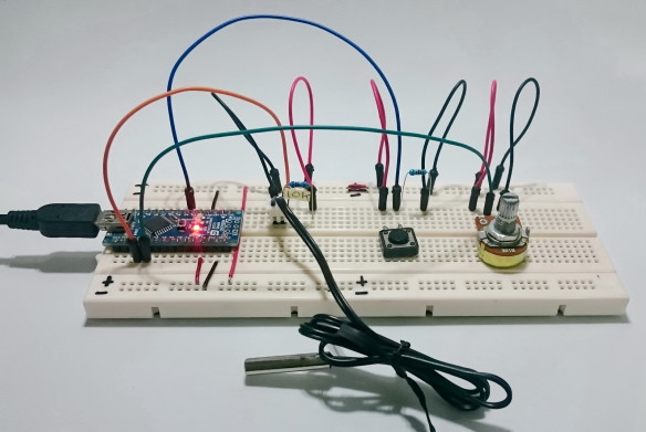
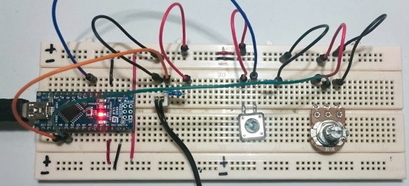
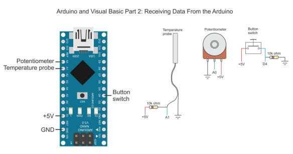
Set up the Arduino with the following:
– The temperature probe is connected to A0.
– The potentiometer is on A1.
– The button switch is connected to D4
Circuit Diagram
Arduino Sketch
The Arduino sketch polls the values of the pins and then, if the value has changed, creates the code and then sends the code out over the serial connection.
/* * * Sketch Arduino to Visual Basic 002 - Receiving Data From the Arduino * * Read pin state / value and send to a host computer over a serial connection. * This is a one way communication; Arduino to a host computer. No data is received from the computer. * * Pins * A0 - a 2 wire temperature probe (sending raw data only. Not the actual temperature) * A1 - a potentiometer * D4 - button switch * The above can be changed to something else * * * It should noted that no data is sent until something changes * The sketch can be expanded so that an initial value is sent * */ // When DEGUG is TRUE send an newline to the serial monitor const boolean DEBUG = true; const byte tempPin = A0; const byte potPin = A1; const byte buttonSwitchPin = 4; unsigned int oldTempVal = 0; unsigned int newTempVal = 0; unsigned int oldPotVal = 0; unsigned int newPotVal = 0; boolean oldButtonSwitchState = false; boolean newButtonSwitchState = false; // used to hold an ascii representation of a number // [10] allows for 9 digits but in this example I am only using 4 digits char numberString[10]; void setup() { // set the button switch pin to input pinMode(buttonSwitchPin, INPUT); // open serial communication Serial.begin(9600); Serial.println("Adruino is ready"); Serial.println(" "); } void loop() { // read the pins newTempVal = analogRead(tempPin); newPotVal = analogRead(potPin); newButtonSwitchState = digitalRead(buttonSwitchPin); if (newTempVal != oldTempVal) { oldTempVal = newTempVal; formatNumber( newTempVal, 4); Serial.print("<T"); Serial.print(numberString); Serial.print(">"); if (DEBUG) { Serial.println(""); } } //The pot I am using jitters +/-1 so I only using changes of 2 or more. if ( abs(newPotVal-oldPotVal) > 1) { oldPotVal = newPotVal; formatNumber( newPotVal, 4); Serial.print("<P"); Serial.print(numberString); Serial.print(">"); if (DEBUG) { Serial.println(""); } } if (newButtonSwitchState != oldButtonSwitchState) { oldButtonSwitchState = newButtonSwitchState; if (oldButtonSwitchState == true) { Serial.print("<BH>"); } else { Serial.print("<BL>"); } if (DEBUG) { Serial.println(""); } } delay (100); } void formatNumber( unsigned int number, byte digits) { // formats a number in to a string and copies it to the global char array numberString // pads the start of the string with '0' characters // // number = the integer to convert to a string // digits = the number of digits to use. char tempString[10] = "\0"; strcpy(numberString, tempString); // convert an integer into a acsii string itoa (number, tempString, 10); // create a string of '0' characters to pad the number byte numZeros = digits - strlen(tempString) ; if (numZeros > 0) { for (int i=1; i <= numZeros; i++) { strcat(numberString,"0"); } } strcat(numberString,tempString); } |
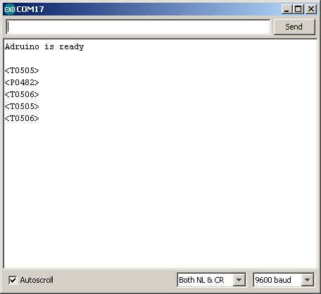
Load the sketch and open the serial monitor. You should get something like the following:
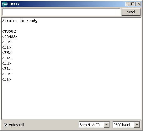
Press the button switch and you should get:
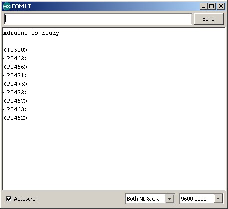
Turn the potentiometer and you should see something similar to:
Now that the Arduino side is working the Visual Basic app is next.
We can use the Visual Basic app from Arduino and Visual Basic Part 1: Receiving Data From the Arduino as the starting point but we need to make some changes. Unlike the previous example, the data is now inside start and end markers and we we need to determine what data we are receiving.
Visual Basic App
The program is fairly simple:
It waits for the user to select a COM port and click the connect button.
It then makes a connection the Arduino.
Checks for incoming serial data
Parses the data
Updates the form.
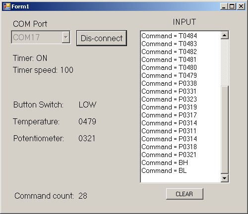
Here is a screen shot of the Visual Basic App in action.
Visual Basic Program
Here is the main form
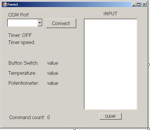
The form is the same one used in the previous example. New labels have been added to show the temperature, the potentiometer value and the switch state. I have also included labels to show the timer interval and the number of commands processed.
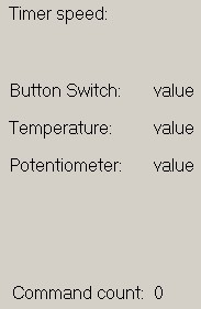
I have left the text box and use it to display the current command. You can also use the text box for debugging.
The code
' ' Arduino and Visual Basic Part 2: Receiving Data From the Arduino ' An example of receiving data from an Arduino using start and end markers ' Imports System Imports System.IO.Ports Public Class Form1 Dim comPORT As String Dim receivedData As String = "" Dim commandCount As Integer = 0 Private Sub Form1_Load(ByVal sender As System.Object, ByVal e As System.EventArgs) Handles MyBase.Load Timer1.Enabled = False TimerSpeed_lbl.Text = "Timer speed: " & Timer1.Interval comPORT = "" For Each sp As String In My.Computer.Ports.SerialPortNames comPort_ComboBox.Items.Add(sp) Next End Sub Private Sub comPort_ComboBox_SelectedIndexChanged(sender As Object, e As EventArgs) Handles comPort_ComboBox.SelectedIndexChanged If (comPort_ComboBox.SelectedItem <> "") Then comPORT = comPort_ComboBox.SelectedItem End If End Sub Private Sub connect_BTN_Click(sender As Object, e As EventArgs) Handles connect_BTN.Click If (connect_BTN.Text = "Connect") Then If (comPORT <> "") Then SerialPort1.Close() SerialPort1.PortName = comPORT SerialPort1.BaudRate = 9600 SerialPort1.DataBits = 8 SerialPort1.Parity = Parity.None SerialPort1.StopBits = StopBits.One SerialPort1.Handshake = Handshake.None SerialPort1.Encoding = System.Text.Encoding.Default 'very important! SerialPort1.ReadTimeout = 10000 SerialPort1.Open() connect_BTN.Text = "Dis-connect" comPort_ComboBox.Enabled = False Timer1.Enabled = True Timer_LBL.Text = "Timer: ON" Else MsgBox("Select a COM port first") End If Else Timer1.Enabled = False SerialPort1.Close() connect_BTN.Text = "Connect" comPort_ComboBox.Enabled = True Timer_LBL.Text = "Timer: OFF" comPort_ComboBox.Text = String.Empty RichTextBox1.Text = "" End If End Sub ' clear the text box Private Sub clear_BTN_Click(sender As Object, e As EventArgs) Handles clear_BTN.Click RichTextBox1.Text = "" End Sub Private Sub Timer1_Tick(sender As Object, e As EventArgs) Handles Timer1.Tick 'stop the timer (stops this function being called while it is still working Timer1.Enabled = False Timer_LBL.Text = "Timer: OFF" ' get any new data and add the the global variable receivedData receivedData = ReceiveSerialData() 'If receivedData contains a "<" and a ">" then we have data If ((receivedData.Contains("<") And receivedData.Contains(">"))) Then parseData() End If ' restart the timer Timer1.Enabled = True Timer_LBL.Text = "Timer: ON" End Sub Function ReceiveSerialData() As String ' returns new data from the serial connection Dim Incoming As String Try Incoming = SerialPort1.ReadExisting() If Incoming Is Nothing Then Return "nothing" & vbCrLf Else Return Incoming End If Catch ex As TimeoutException Return "Error: Serial Port read timed out." End Try End Function Function parseData() ' uses the global variable receivedData Dim pos1 As Integer Dim pos2 As Integer Dim length As Integer Dim newCommand As String Dim done As Boolean = False While (Not done) pos1 = receivedData.IndexOf("<") + 1 pos2 = receivedData.IndexOf(">") + 1 'occasionally we may not get complete data and the end marker will be in front of the start marker ' for exampe "55><T0056><" ' if pos2 < pos1 then remove the first part of the string from receivedData If (pos2 < pos1) Then receivedData = Microsoft.VisualBasic.Mid(receivedData, pos2 + 1) pos1 = receivedData.IndexOf("<") + 1 pos2 = receivedData.IndexOf(">") + 1 End If If (pos1 = 0 Or pos2 = 0) Then ' we do not have both start and end markers and we are done done = True Else ' we have both start and end markers length = pos2 - pos1 + 1 If (length > 0) Then 'remove the start and end markers from the command newCommand = Mid(receivedData, pos1 + 1, length - 2) ' show the command in the text box RichTextBox1.AppendText("Command = " & newCommand & vbCrLf) 'remove the command from receivedData receivedData = Mid(receivedData, pos2 + 1) ' B for button switch If (newCommand(0) = "B") Then If (newCommand(1) = "L") Then buttonSwitchValue_lbl.Text = "LOW" ElseIf (newCommand(1) = "H") Then buttonSwitchValue_lbl.Text = "HIGH" End If End If ' (newCommand(0) = "B") ' P for potentiometer If (newCommand.Substring(0, 1) = "P") Then potentiometerValue_lbl.Text = newCommand.Substring(1, 4) End If '(newCommand.Substring(0, 1) = "P") 'T for temperature If (newCommand.Substring(0, 1) = "T") Then temperatureValue_lbl.Text = newCommand.Substring(1, 4) End If '(newCommand.Substring(0, 1) = "P") commandCount = commandCount + 1 commandCountVal_lbl.Text = commandCount End If ' (length > 0) End If '(pos1 = 0 Or pos2 = 0) End While End Function End Class |
Code run through
on start up, the Form1_Load function is called. This updates the timer interval label, and populates the combobox with the available COM ports.
Private Sub Form1_Load(ByVal sender As System.Object, ByVal e As System.EventArgs) Handles MyBase.Load Timer1.Enabled = False TimerSpeed_lbl.Text = "Timer speed: " & Timer1.Interval comPORT = "" For Each sp As String In My.Computer.Ports.SerialPortNames comPort_ComboBox.Items.Add(sp) Next End Sub |
The program then waits for the user to select a COM port and hit the Connect button. If the Connect button is clicked without a COM port selected an error message is displayed. If a COM port has been selected then the serial port attributes are set and the program tries to open the port. If successful the Connect button text is change to “Dis-connect” and the timer started. The timer is used to check for incoming data. The timer is set to 100ms. This means there are 10 checks a second to see if there is any new serial data.
If there is an existing connection (the Connect button text is not equal to “Connect”) then the serial port is closed.
Private Sub comPort_ComboBox_SelectedIndexChanged(sender As Object, e As EventArgs) Handles comPort_ComboBox.SelectedIndexChanged If (comPort_ComboBox.SelectedItem <> "") Then comPORT = comPort_ComboBox.SelectedItem End If End Sub Private Sub connect_BTN_Click(sender As Object, e As EventArgs) Handles connect_BTN.Click If (connect_BTN.Text = "Connect") Then If (comPORT <> "") Then SerialPort1.Close() SerialPort1.PortName = comPORT SerialPort1.BaudRate = 9600 SerialPort1.DataBits = 8 SerialPort1.Parity = Parity.None SerialPort1.StopBits = StopBits.One SerialPort1.Handshake = Handshake.None SerialPort1.Encoding = System.Text.Encoding.Default 'very important! SerialPort1.ReadTimeout = 10000 SerialPort1.Open() connect_BTN.Text = "Dis-connect" comPort_ComboBox.Enabled = False Timer1.Enabled = True Timer_LBL.Text = "Timer: ON" Else MsgBox("Select a COM port first") End If Else Timer1.Enabled = False SerialPort1.Close() connect_BTN.Text = "Connect" comPort_ComboBox.Enabled = True Timer_LBL.Text = "Timer: OFF" comPort_ComboBox.Text = String.Empty RichTextBox1.Text = "" End If End Sub |
When the timer function is called, any new serial data is added to a buffer in the form of a global variable called receivedData. Adding the new data to a buffer like this ensures we get full commands. Only checking the latest received data means we are likely to miss commands. The received data could be fragmented like this; “34<“, “T011”, “1><BH><P0245><BL><T01”.
If the buffer contains a start marker (“<“) and also an end marker(“>”) then we have a complete command (not 100% true!) and the function parseData() is called. Because receivedData is a global variable we do not need to pass it to the parseData() function.
Private Sub Timer1_Tick(sender As Object, e As EventArgs) Handles Timer1.Tick 'stop the timer (stops this function being called while it is still working Timer1.Enabled = False Timer_LBL.Text = "Timer: OFF" ' get any new data and add the the global variable receivedData receivedData = ReceiveSerialData() 'If receivedData contains a "<" and a ">" then we have data If ((receivedData.Contains("<") And receivedData.Contains(">"))) Then parseData() End If ' restart the timer Timer1.Enabled = True Timer_LBL.Text = "Timer: ON" End Sub |
All the heavy work is done in the parseData() function.
Because the received data buffer may have more than one command the function loops through the received data removing the first complete command from the buffer on each loop. The positions of the start and end markers are used to determine if we still have a complete command.
pos1 = receivedData.IndexOf("<") + 1 pos2 = receivedData.IndexOf(">") + 1 If (pos1 = 0 Or pos2 = 0) Then ' we do not have both start and end markers and we are done done = True |
Using the positions of the first start and end markers the first command can be copied to the variable newCommand.
length = pos2 - pos1 + 1 If (length > 0) Then 'remove the start and end markers from the command newCommand = Mid(receivedData, pos1 + 1, length - 2) ' show the command in the text box RichTextBox1.AppendText("Command = " & newCommand & vbCrLf) 'remove the command from receivedData receivedData = Mid(receivedData, pos2 + 1) |
Once we have the command we can check which one it is and update the form.
' B for button switch If (newCommand(0) = "B") Then If (newCommand(1) = "L") Then buttonSwitchValue_lbl.Text = "LOW" ElseIf (newCommand(1) = "H") Then buttonSwitchValue_lbl.Text = "HIGH" End If End If ' (newCommand(0) = "B") ' P for potentiometer If (newCommand.Substring(0, 1) = "P") Then potentiometerValue_lbl.Text = newCommand.Substring(1, 4) End If '(newCommand.Substring(0, 1) = "P") 'T for temperature If (newCommand.Substring(0, 1) = "T") Then temperatureValue_lbl.Text = newCommand.Substring(1, 4) End If '(newCommand.Substring(0, 1) = "P") commandCount = commandCount + 1 commandCountVal_lbl.Text = commandCount |
Next up: Arduino and Visual Basic Part 3: Controlling an Arduino
Thank you for this article- I still did not read it but it looks good- I will try it pretty soon- again thanks for you effort
I ran the program and sometimes it works good and sometimes it gets stuck.
The VB says (after it compiles the program) that there might be a null exeption when running the program since the parse() function may not return a value for all cases. Is there a cure for that?
Appreciate an answer to my E- mail
Thanks a lot
Hi Dan,
I haven’t used this for a while but I never had an issue in the past and I use the same code on my dropController project which runs without a problem.
The parseData() does not return a value. It looks for the start and end markers and then takes the data they contain. If it finds data it checks what the data is.
Can you post a more specific error and possible show the program line in the code.
The null you see from the vb could be an empty com port. Or not existing tha port
I have the same issue
By the way it is very good example and very well comment, it helps a lot !!!! Well done!!!
Kind regards
Tasos
Hi Martyn,
I have a problem and was wondering if you could guide what the issue could be?
Setup:
I setup a board with 2 switches, Switch A and Switch B. Switch A = Pin D2 and Switch B = Pin D4. Used the same code of yours in the vb software to monitor both pins. In the arduino, I programmed them as AH, AL (for Switch A) and BH, BL (for Switch B). Attached 10K ohm resistor against Switch A as per your diagram and again one more 10K ohm resistor against Switch B in the same manner and polarity.
Power Source: USB from the laptop (no external power).
Problem:
Both the pin outputs keep swapping between H and L after every few seconds (ranges between 3 seconds to 15 seconds but averages at about 6-8 seconds). Could there be an issue with the circuitry? By turning on/off the switch – i am still not able to make out if its affecting the signals as the output keeps swapping between H and L for both pins every few seconds.
Could you guide what could be the issue?
Hi Martyn,
Here is a sample output with timestamp. You can notice the difference in seconds. This keeps repeating for ever.
00:30:40 – Command = AL
00:30:40 – Command = BL
00:30:47 – Command = AH
00:30:47 – Command = BH
00:30:50 – Command = AL
00:30:50 – Command = BL
00:30:58 – Command = AH
00:30:58 – Command = BH
00:31:02 – Command = AL
00:31:02 – Command = BL
00:31:09 – Command = AH
00:31:09 – Command = BH
00:31:13 – Command = AL
00:31:13 – Command = BL
00:31:20 – Command = AH
00:31:21 – Command = BH
00:31:24 – Command = AL
00:31:24 – Command = BL
My first thought is an issue with the switches or lose connections. Are you moving the circuit while using it?
Try different switches if you can. If not, remove the switches and replace with a short length of wire and then use the wire as a switch.
Also try just using the serial monitor.
Hi Martyn,
Thanks for your guidance. Yes, I verified everything that you said. The circuit is not moving, its static on a table. Infact, I dont have switches at the moment as I am still prototyping. I am using two short wires instead as a switch.
Upon further research, I found many people are having similar issues. I even measured the voltage across the pins in a H and L state and they were reporting 0.45-0.50 volts – which is almost an OFF state.
I found there could be 2 possible issues:
1) Circuit is incorrect. I will start from scratch again. This is because voltage drop across the PINs are 0.45v during H and L – indicates an incorrect circuit setup.
2) The OFF and ON swaps are explained due to tri-state of the PINs. I read a lot about everyone having this issue. One link here: https://forum.arduino.cc/index.php?topic=183977.0 and many of them are suggesting different methods to rule out the tri-state of the PINS.
I will address both issues above if possible and post the outcome soon. Thanks a lot for your guidance though and it was helpful to start looking in the right direction towards trouble shooting the issue.
Also, Yes, Output in Serial Monitor was also behaving the same way as explained yesterday.
Thanks so much. I will keep you posted on how this goes.
Regards,
John.
Here’s the link http://arduino.stackexchange.com/questions/12951/testing-tri-state-pin-erroneous-results-with-internal-pullup/12955#12955 that explains the behaviour I was having. Unfortunately, I am not very good at designing circuits, so I cannot interpret how to come up with the schematics for this suggestion, so i will have to consult someone or maybe you could help with a diagram if time allows you. If not, its ok, i will manage somehow. Isn’t this the exact behavior i reported initially? pretty much so.
Thanks once again. Will post further updates.
Regards,
John.
I would expect this behaviour if the pin was floating, do you have the it set for input?
What is the voltage from the VCC rail? The opposite side of the switch. This is marked +5V on the switch in the diagram above.
You also try switching the polarity of the switch. Make the resistor pullup and then connect the switch to GND. This swaps how the switch works. HIGH is not pressed, GND is pressed.
Hi Mark,
See my responses below.
I would expect this behaviour if the pin was floating, do you have the it set for input?
Yes, both were set to INPUT.
What is the voltage from the VCC rail? The opposite side of the switch. This is marked +5V on the switch in the diagram above.
Constantly getting >4.5v.
You also try switching the polarity of the switch. Make the resistor pullup and then connect the switch to GND. This swaps how the switch works. HIGH is not pressed, GND is pressed.
Am bad at understanding electronic language technically but I sort of get the idea of what you are suggesting. Also, I even tried adding >1M Ohm resistor and using that PULLUP PIN idea from the other post – even that didn’t work.
Going by your suggestion to use PULLUP, I found a way to make it work. Not sure if this is good enough for a production environment but the outcome is perfectly as expected.
I removed all the resistors and converted both the pins from INPUT to INPUT_PULLUP. Then, directly connected pins to switch (aka the 2 wires as I do not have physical switches) and from switch to ground thereby using the internal pullups of the nano. It worked perfectly after that. Only had to reverse the logic like you suggested that it would return HIGH when not pressed and GND when pressed.
This was my new schematic setup here https://www.arduino.cc/en/Tutorial/InputPullupSerial and I setup 2 switches instead of one with the changes explained above and now it works perfectly. Thank you so much for your suggestions and directions.
Thanks for all your help.
I would still be interested to resolve the issue with your suggestion though. I am still not convinced why it didn’t work with the external resistors and I will update you when i get to work on it.
But for now – it worked perfect after using both pins as pullups.
Thanks for all your help.
Cheers.
Regards,
John.
Thank you so much for this posting. It was exactly what I needed to start a project. Your
sharing is greatly appreciated.
halo sir,
I want to ask something about this project, i made something a little different from the program you created, i just use push button without potentiometer etc, i set the program on arduino to send serial data “” if pushbutton one is pressed and ” “If not pressed, I try to simplify the program you have created with the sole purpose of changing the text label and changing the fill color of a shape I have created using the program in the timer1 section as follows:
Private Sub Timer1_Tick (ByVal sender As System.Object, ByVal e As System.EventArgs) Handles Timer1.Tick
ReceivedData = ReceiveSerialData ()
Tbxinput.Text & = receivedData
If (receivedData = “”) Then
Lbllampu1.Text = “lampu1: On”
Lampu1.FillColor = Color.Blue
End If
End Sub
No error message appears but the program does not work as I like(the text label is unchanged and the fill color does not change), can you show me where the mistake I made and how it should be, please help me, thanks
Don’t use “” use something with an actual value like “Lamp: Off”. On the Arduino, keep the switch state in a variable and only send “Lamp: Off” when the state changes to off.
I’m sorry sir, I do not mean to write “” (empty) in the comment field, but I write (“”), if I write “” + (inside), the word in it suddenly disappears after the comment is sent and I do not know why Like that, sorry I did not realize it
Back to my program, actually what I mean in the “” sign is not empty, but there is a word if push button on press and if pushbutton is removed and with the program I use above does not work as desire
Why if i write in comment always disappear hehehe
I just change the serial data I send from arduino because if the write in this comment always disappear: P, sorry sir I repeat the question
I send the data serial “1H” if pushbutton is pressed, and “1L” if pushbutton is released, the serial data is received and read in the textbox, and I want to use it to change the text and change the shape color,
ReceivedData = ReceiveSerialData ()
Tbxinput.Text & = receivedData
If (receivedData = “1H”) Then
Lbllampu1.Text = “lampu1: On”
Lights1.FillColor = Color.Blue
End If
End Sub
No error message appears but the program does not work as I like (the text label is unchanged and the fill color does not change), can you show me where the mistake I made and how it should be, please help me, thanks
I suspect the value of receivedData is not just 1H. Are there additional characters, possibly non print characters?
Check the length of receivedData.
I am working on a project similar to the one described here. Also, I have read Part 1 of this post.
I want a connection of 4 to 5 push buttons (e.g A,B,C,D), a RFID reader and a few RFID tags. For example when button ‘A’ is pressed, I want to record ‘A’ into a tag that is placed before the reader. Besides, I want to keep count of how many times each button has be pressed and send this information to my VB.Net application.
I am a final year student of computer science with no electronic background. My project is a little more complex but this aspect is a major hurdle for me to overcome. Everyone, please help me on this. I would also want to know what electronic components are needed to accomplish this task.
If you feel the information is not sufficient, please let me know. Thank you very much.
I think there is a little bug in the software.
if (newButtonSwitchState != oldButtonSwitchState)
{
oldButtonSwitchState = newButtonSwitchState;
–> if (oldButtonSwitchState == true)
I think that it should be “newButtonSwitchState”
At that point their values are the same so it doesn’t really matter.
sorry sir,
i wanna ask about, how we read the digitalwrite in arduino and then send to VB10, which in VB10, when we got the data that change the backcolor of a shape.
to make it clear for exmple
make a code of traffic light and in VB just monitoring.
i mean when the light change in arduino, arduino send the data to VB and the shape of the lamp is changed in the VB
thanks before
grazie ho usato questa trasmissione per il mio progetto
ho modificato con un ingresso interrupt arduino 0/1
e altro ingresso per badge
e altro per ingresso 0/1
per mio progetto industria 4.0
Hi Martyn,
I’m working on a personal project and found your project by searching on google. Your project is great!
I would have question given that I am not familiar with transmitting and receiving string I would like to know just how I can in VB.net transmit data from three trackBar and receive them with Arduino.
I studied your code but and did some tests but without success :-(
thanks for your help
Chris
I tried this vb code. And I am having an issue with the parsedata(). I am pressing a button that sends a command to the arduino. The received response is first printed in the richtextbox1 just like your code but then in the parse data() I am checking the received response string within the start and end markers, if it contains a certain set of characters I am printing the string in another textbox.
Now the issue I am facing is. For most cases I am able to see the string getting printed in the textbox. But sometimes the printing is not happening, even when I am receiving the correct response in the rich textbox1. I ran the debugger and used breakpoints and realised that at times the parse data() is not able to recognize the end marker. This pos2 becomes 0 and the while loop terminates due to which print operation does not occur.
I know it’s been really long since you posted this. But it would be very helpful if you could help me with my problem.
Hoping to hear from you in the mail.
Thank you