In the last post I briefly talked about different data formats and how I recommend keeping things as simple as possible. With this is mind, for a first project let’s create a simple blinking LED. We will have one Arduino controlling an LED on a second Arduino.
Controls to turn the LED on or off will be sent via serial from the first Arduino to the second Arduino. This is as basic as it gets. Arduino Blink by remote control. The LED has only two states so simple control codes can be used and to start I am using 1 of on and 0 for off.
In these examples I am using Arduino Nanos but any kind of Arduino can be used and for this series I am using Arduino to Arduino communication. The techniques are exactly the same for any UART to UART device. For example, in Arduino to Arduino by Bluetooth I use exactly the same serial communication techniques to send commands wirelessly over Bluetooth.
Example #1: Remote Control Blink
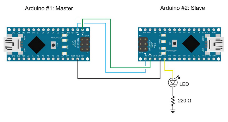
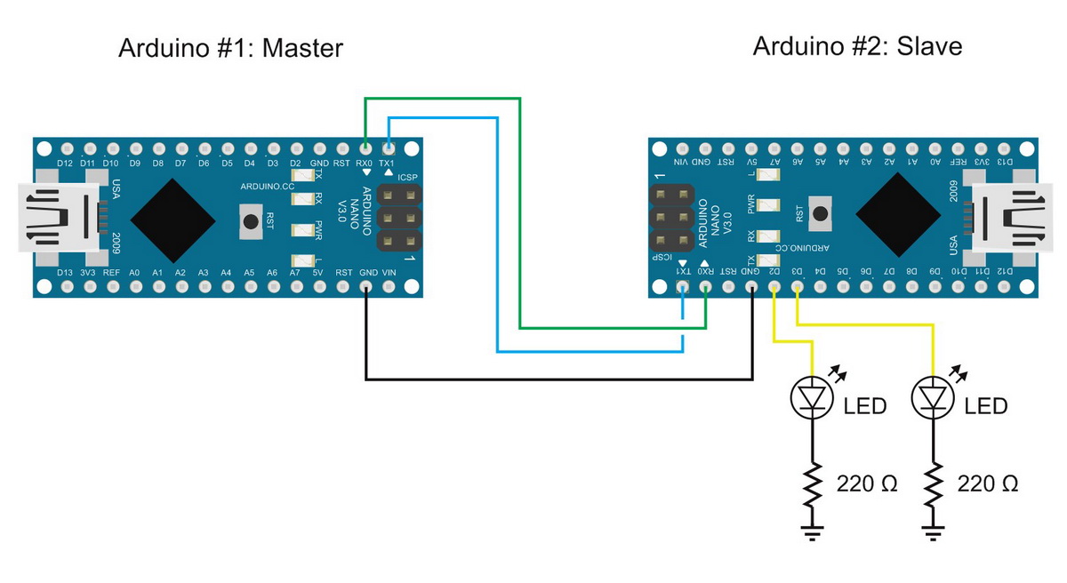
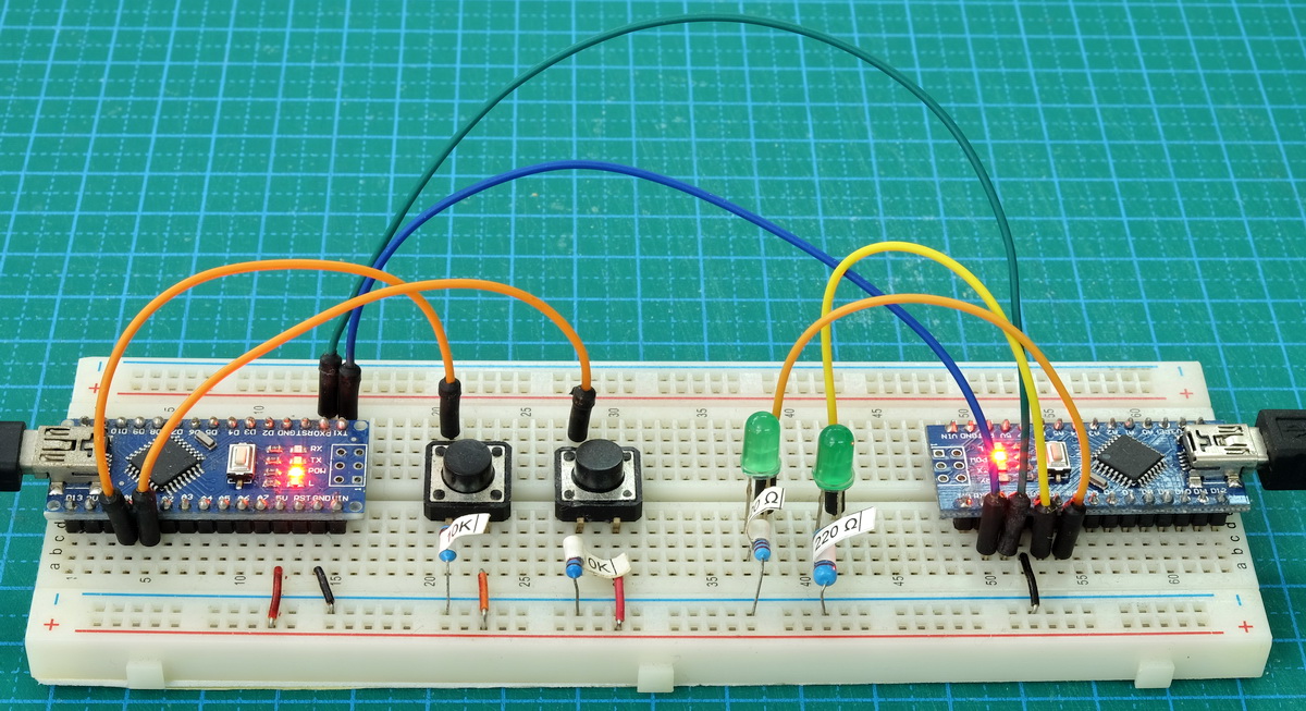
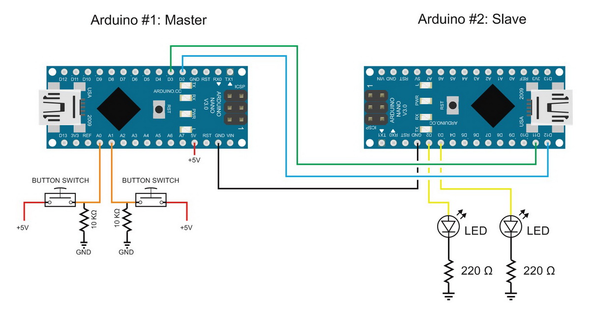
Simply circuit consisting of 2 Arduinos with the following connections:
Pin 0 (RX) on the Arduino #1 goes to pin 1 (TX) on Arduino #2.
Pin 1 (TX) on the Arduino #1 goes to pin 0 (RX) on Arduino #2.
Arduino #1 GND to Arduino #2 GND
Arduino #2 D2 to LED + Resistor (220 or 330 ohm)
Example #3. Sketch: Remote Control Blink
The master Arduino transmits the commands:
// Arduino Serial Example #1 Remote Control Blink - Master
// www.martyncurrey.com

void setup()
{
    Serial.begin(9600);
    // wait for the serial port to connect. Required for Leonardo/Micro native USB port only
    while (!Serial) {  ;  }
}


void loop()
{
  Serial.print(1);
  delay(1000);
  Serial.print(0);
  delay(1000);
}
The slave Arduino receives the commands. If it receives a 1 it turns on the lED and if it receives a 0 it turns off the LED.
// Arduino Serial Example #1 Remote Control Blink - Slave
// www.martyncurrey.com

char c  = ' ';
byte LED = 2;

void setup()
{
   pinMode(LED, OUTPUT);
   Serial.begin(9600);
   Serial.println("START");
}


void loop()
{
   if(Serial.available())
   {
      char c = Serial.read();
      if (c=='0') { digitalWrite(LED, LOW); }
      if (c=='1') { digitalWrite(LED, HIGH); }
      Serial.println(c);
   }

}
This is pretty basic.
Arduino #1 transmits a “1” waits a second then transmits a “0” then waits another second and starts again.
It is worth mentioning that Arduino #1 will happily keep transmitting the values whether or not there is anything listening.
Remember when you use Serial.print() numbers are converted to ascii. This means the actual values transmitted are 48 for 0 and 49 for 1. This is important to know for when you create the code for the receiving Arduino.
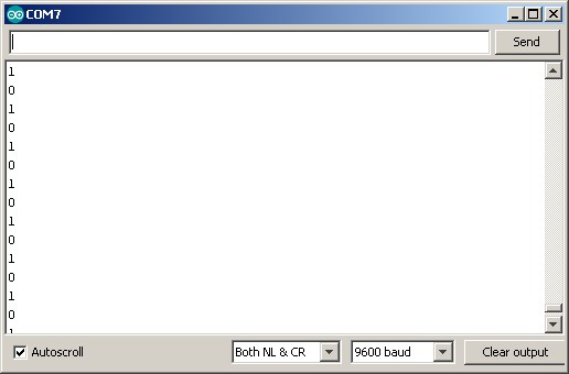
The sketch on Arduino #2 initializes a hardware Serial channel, prints a “START” message to the serial monitor, and then keeps checking for incoming data. The loop() function is where the magic happens.
if(Serial.available())
   {
    char c = Serial.read();
    Serial.println(c);

    if (c=='0') { digitalWrite(LED, LOW); }
    if (c=='1') { digitalWrite(LED, HIGH); }
  }
First a check is made to see if there is any data in the Serial buffer
char c = Serial.read();At this point we have a value in “c”. We are only interested is “0” and “1” so the next bit checks for these values.
if (c=='0') { digitalWrite(LED, LOW); }
if (c=='1') { digitalWrite(LED, HIGH); }
If c==’0′ the LED is turned off with digitalWrite(LED, LOW); and if c==’1′ the LED is turned on with digitalWrite(LED, HIGH);. Any other value is ignored.
Notice that 0 and 1 are inside single quotes. This is because they are the ascii characters and I am using a char variable. With chars use single quotes ‘0’ and ‘1’ not double quotes such as “0” and “1”. Because I am using a char I could have also checked the actual value rather than the ascii character
Since we are only interested is “1”s and “0”s everything else is ignored. It is possible for the master device to send any character but the slave only acts on the “1”s and “0”s.
The below works in exactly the same way but is slightly harder to read.
if (c==48) { digitalWrite(LED, LOW); }
if (c==49) { digitalWrite(LED, HIGH); }
If you have already built the circuit you will need to remove the serial connections before uploading the sketches. If you forget to remove the serial connections the IDE will attempt to upload, fail and eventually timeout. Of course, after the upload you need to reconnect. This is one of the problems with using hardware serial and the disconnection / reconnection quickly gets annoying.
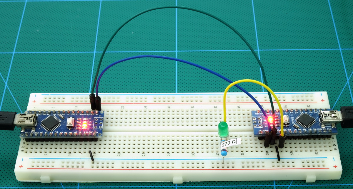
Upload the sketches and you should have Remote Blink. Remember it is the master Arduino that is controlling the LED.
You can also check the received data by opening the serial monitor on the slave Arduino.
Example #2: Remote Control Blink. 2 LEDs
Using the same technique it is fairly simply to add a second LED so let’s try it. Connect a second LED (plus resistor) to the Slave Arduino on pin D3.
Example #3. Sketch: Remote Control Blink With 2 LEDs
// Arduino Serial Example #2 Remote Control Blink With 2 LEDs -Master
// www.martyncurrey.com

void setup()
{
    Serial.begin(9600);
    // wait for the serial port to connect. Required for Leonardo/Micro native USB port only
    while (!Serial) {  ;  }
}


void loop()
{
  Serial.print(1);
  Serial.print(3);
  delay(1000);
  Serial.print(0);
  Serial.print(2);
  delay(1000);
}
I have added 2 more commands used to control the second LED:
“3” to turn on the LED, and
“2” to turn it off.
// Arduino Serial Example #2 Remote Control Blink With 2 LEDs - Slave
// www.martyncurrey.com

char c  = ' ';
byte LED1 = 2;
byte LED2 = 3;

void setup()
{
   pinMode(LED1, OUTPUT);
   pinMode(LED2, OUTPUT);

   Serial.begin(9600);
   Serial.println("START");
}

void loop()
{
   if(Serial.available())
   {
      char c = Serial.read();
      if (c=='0') { digitalWrite(LED1, LOW); }
      if (c=='1') { digitalWrite(LED1, HIGH); }
      if (c=='2') { digitalWrite(LED2, LOW); }
      if (c=='3') { digitalWrite(LED2, HIGH); }
      Serial.println(c);
   }

}
The two new commands are taken care of with
if (c=='2') { digitalWrite(LED2, LOW); }
if (c=='3') { digitalWrite(LED2, HIGH); }
You should be able to see that more LEDS can be added simply by using more commands.
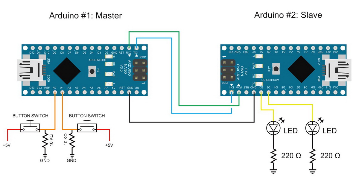
Example #3: Remote Control With Push Button Switches
The above works well and is very reliable but if all you want to do is turn something on and off at regular intervals there is no need to use two Arduinos. So, next we make things a little more complex by adding a couple of switches to control the LEDs.
To the existing circuit, on Arduino #1 add a button switch on pin A0/D14 and A1/D15. If you don’t already know, analogue pins can be used as digital pins (except A5 & A6 which are analogue only). I only reason picked these pins is so the circuit diagram looked neat. No other reason.
I don’t spend much time on explaining the button switch code, if you are interested in learning more about this see the Turning things on and off guides.
Example #3. Sketch: Remote Control With Push Button Switches
// Example #3. Sketch: Remote Control With Push Button Switches. Master
// www.martyncurrey.com


byte buttonSwitch1 = 14;
byte buttonSwitch2 = 15;

boolean buttonState1 = false;
boolean buttonState2 = false;
boolean buttonState3 = false;

boolean buttonSwitch1_State_old = false;
boolean buttonSwitch2_State_old = false;


void setup()
{
    Serial.begin(9600);
    // wait for the serial port to connect. Required for Leonardo native USB port only
    while (!Serial) {  ;  }
    Serial.print("Start");

}

void loop()
{
  // simple debounce
  buttonState1 = digitalRead(buttonSwitch1); delay(1);
  buttonState2 = digitalRead(buttonSwitch1); delay(1);
  buttonState3 = digitalRead(buttonSwitch1); delay(1);

  if ( (buttonState1 == buttonState2) && (buttonState1 == buttonState3) )
  {
     // has the button switch state changed?
     if (buttonState1 != buttonSwitch1_State_old)
     {
        buttonSwitch1_State_old = buttonState1;
        if (buttonSwitch1_State_old == HIGH) { Serial.print(1);}  else  { Serial.print(0);}
     }
  }


  buttonState1 = digitalRead(buttonSwitch2); delay(1);
  buttonState2 = digitalRead(buttonSwitch2); delay(1);
  buttonState3 = digitalRead(buttonSwitch2); delay(1);

  if ( (buttonState1 == buttonState2) && (buttonState1 == buttonState3) )
  {
     // has the button switch state changed?
     if (buttonState1 != buttonSwitch2_State_old)
     {
        buttonSwitch2_State_old = buttonState1;
        if (buttonSwitch2_State_old == HIGH) { Serial.print(3);} else { Serial.print(2);}
     }
  }

}
The state of the button switches are checked and if the state has changed a control code is sent. The main bit is that the codes are only sent when the switch position changes.
The slave sketch has not changed.
// Example #3. Sketch: Remote Control With Push Button Switches. Slave
// www.martyncurrey.com

char c  = ' ';
byte LED1 = 2;
byte LED2 = 3;

void setup()
{
   pinMode(LED1, OUTPUT);
   pinMode(LED2, OUTPUT);

   Serial.begin(9600);
   Serial.println("START");
}


void loop()
{
   if(Serial.available())
   {
      char c = Serial.read();
      if (c=='0') { digitalWrite(LED1, LOW); }
      if (c=='1') { digitalWrite(LED1, HIGH); }
      if (c=='2') { digitalWrite(LED2, LOW); }
      if (c=='3') { digitalWrite(LED2, HIGH); }
      Serial.println(c);
   }

}
Now, instead of using a timer to send the commands button switches are used. Close a switch and an LED comes on. Open the switch and the LED turns off.
I find it a little annoying that the switches turn on the wrong LEDs but I will leave you to change it if you so wish.
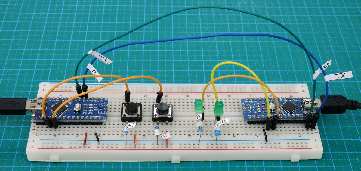
Example #4: Remote Control Blink Using Software Serial
If you followed along with the examples I suspect you were, at least a little, annoyed that you had to keep removing and reconnecting the wires to the serial pins. While writing this guide I forgot at least a couple of times.
Although hardware serial is always the best choice if it is available to you it can be frustrating when developing the code. In the rest of the examples I will start using one of the software serial libraries. If you remember from the earlier guide, the best option is AltSoftSerial followed by NeoSerial with the default SoftwareSerial at the end. In this example I change the example 3 from hardware serial to software serial using the software serial library that comes with the Arduino IDE. Not the best choice but useful is this scenario.
Technically you can use pins 0 and 1 for software serial but that would defeat what I am wanting to do, so, on the master Arduino I am using pins 2 and 3 (2 for TX and 3 for RX) and on the slave Arduino I am using pins 11 and 12 (11 for RX and 12 for TX).
Example #4 Remote Control Blink Using Software Serial
// Example #4 Remote Control Blink Using Software Serial - Master
// www.martyncurrey.com


#include <SoftwareSerial.h>
SoftwareSerial SoftSerial(2, 3); // RX, TX


byte buttonSwitch1 = 14;
byte buttonSwitch2 = 15;

boolean buttonState1 = false;
boolean buttonState2 = false;
boolean buttonState3 = false;

boolean buttonSwitch1_State_old = false;
boolean buttonSwitch2_State_old = false;


void setup()
{
    SoftSerial.begin(9600);
}

void loop()
{
  // simple debounce
  buttonState1 = digitalRead(buttonSwitch1); delay(1);
  buttonState2 = digitalRead(buttonSwitch1); delay(1);
  buttonState3 = digitalRead(buttonSwitch1); delay(1);

  if ( (buttonState1 == buttonState2) && (buttonState1 == buttonState3) )
  {
     // has the button switch state changed?
     if (buttonState1 != buttonSwitch1_State_old)
     {
        buttonSwitch1_State_old = buttonState1;
        if (buttonSwitch1_State_old == HIGH) { SoftSerial.print(1);}  else  { SoftSerial.print(0);}
     }
  }


  buttonState1 = digitalRead(buttonSwitch2); delay(1);
  buttonState2 = digitalRead(buttonSwitch2); delay(1);
  buttonState3 = digitalRead(buttonSwitch2); delay(1);

  if ( (buttonState1 == buttonState2) && (buttonState1 == buttonState3) )
  {
     // has the button switch state changed?
     if (buttonState1 != buttonSwitch2_State_old)
     {
        buttonSwitch2_State_old = buttonState1;
        if (buttonSwitch2_State_old == HIGH) { SoftSerial.print(3);} else { SoftSerial.print(2);}

     }
  }

}
You can see that I have removed the line that initialized the hardware serial and replaced it with
SoftSerial.begin(9600);Where did “SoftSerial” come from? It is what I called the instance of the software serial I am using and this is done when you declare the library. I could have used any name (within reason), for example SWS or sSerial.
#include <SoftwareSerial.h>
SoftwareSerial SoftSerial(2, 3); // RX, TX
When declaring the software serial library you need to specify what pins to use. Here I am telling it to use pin D2 for receive and D3 for transmit.
// Example #4 Remote Control Blink Using Software Serial - Slave
// www.martyncurrey.com

#include <SoftwareSerial.h>
SoftwareSerial SoftSerial(11, 12); // RX, TX


char c  = ' ';
byte LED1 = 2;
byte LED2 = 3;

void setup()
{
   pinMode(LED1, OUTPUT);
   pinMode(LED2, OUTPUT);

   SoftSerial.begin(9600);
}


void loop()
{
   if(SoftSerial.available())
   {
      char c = SoftSerial.read();
      if (c=='0') { digitalWrite(LED1, LOW); }
      if (c=='1') { digitalWrite(LED1, HIGH); }
      if (c=='2') { digitalWrite(LED2, LOW); }
      if (c=='3') { digitalWrite(LED2, HIGH); }
   }

}
In the slave sketch, pins D2 and D3 are already used (bad planning I know) so I have used D11 and D12
#include <SoftwareSerial.h>
SoftwareSerial SoftSerial(11, 12); // RX, TX
If you give this a try you will find it works exactly the same as example 3 above. The difference is we do not need to remove the serial connections to upload a new sketch.
This has been a very gentle introduction in to using serial communication to send control codes from Arduino to Arduino. Using single character codes or controls allows you to keep the code simple. A single character can be loaded in to a char or byte variable which is easy to compare or check with a simple ==. There is no need for char arrays or strings. If the character is not something we want it can be ignored and the next character read.
   if(SoftSerial.available())
   {
      char c = SoftSerial.read();
      if (c=='0') { digitalWrite(LED1, LOW); }
      if (c=='1') { digitalWrite(LED1, HIGH); }
      if (c=='2') { digitalWrite(LED2, LOW); }
      if (c=='3') { digitalWrite(LED2, HIGH); }
   }
A key point to highlight is that the serial buffer is checked for data before attempting to read from it. This allows for non-blocking code that continues to work until there is data to process.
Excelent wor man, it was very helpful to me like as a beginner in arduino.
I want to know if you could help me, how to send an analog reading.
Anyone interested in doing Arduino to Arduino serial communication, check out this library that handles all of the difficult parsing for you (it even includes delimiting, Consistent Overhead Byte Stuffing (COBS), and Cyclic Redundancy Checking (CRC)): https://github.com/PowerBroker2/SerialTransfer
The library looks good.
If I can make a suggestion, it could do with more examples and a description of what it actual does.
That looks very straightforward, much appreciated. Would triggering the Adafruit Neopixel or FastLED library on the slave work? The problem with those two is that they temporarily disable interrupts to write data to LED strips or rings, hence the idea to use a nano slave to do the “dirty” work and not mess with code running on the master.
It would not effect hardware serial but would effect some of the software serials.
Great tutorial!
The diagram has TX connected to TX (blue) and RX connected to RX (green). That cannot work (the explanation is alright, the diagram is wrong).
You’re right. The code works The hardware is bad.
I have tried all the examples and it works very well.
Thanks and congratulations. Correct the plane
Thanks for the heads up. I have corrected the diagram.
I dont understand this im sorry.. everything works well when i send commands 0 to 9 from my esp8266 module to my arduino mega2560 using sws. When trying to send more characters like 10 -> the receiving arduino does not react.. the reason i am using softwareserial is that hardwareserial is being used and occupied by Nextion HMI display..
Sorry, i’m new to this, and tried your other examples as well, but i dont know what im doing wrong..
I want to send atleast 0-99 commands from my esp8266 to slave arduinos to execute simple on/off tasks..
You better persons please mock me, but i would be apreciated for help with this..
In the above examples I am using serial.print() which converts values to their ascii representation. value 1 becomes ‘1’, value 2 becomes ‘2’. This means, when you send the value 10 it gets converted to ’10’, 2 characters. Rather than using 10,11,12.. use a,b,c or A,B,C.
If you want to send the actual value, use serial.write(). But note, the max value you can send is 255 (1 byte).