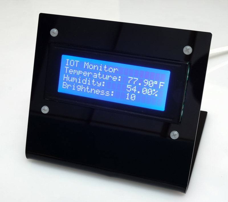
In this final part of this series I add a network connection manager, add a couple of extra functions, add a stand, fix a couple of problems.
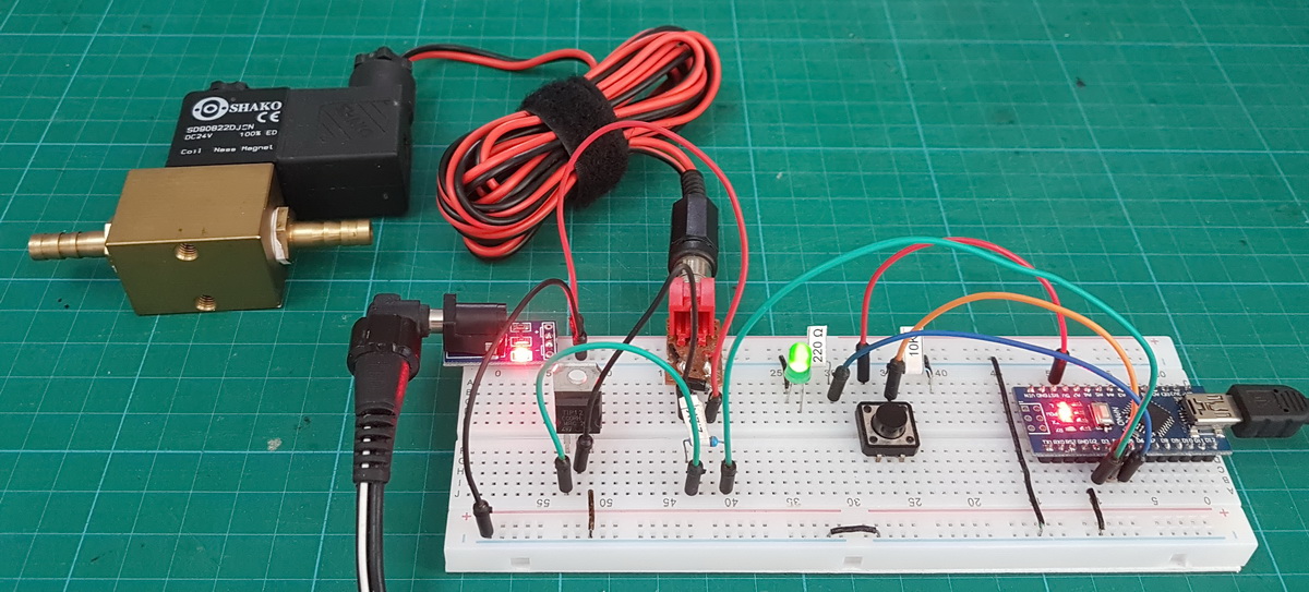
Here is the final project.
Arduino, ESP32/8266, Bluetooth, and stuff
Connecting 2 Arduinos using 2 HM-10s is fairly easy. It is straight forward to make a connection and once the connection is established the HM-10s UART layer does all the work for you. The UART layer does mean you have no control over the actual BLE details though. To make a connection, all you need … Read more
In this final part of this series I add a network connection manager, add a couple of extra functions, add a stand, fix a couple of problems.
Here is the final project.
25.06.2020: Updated the circuit diagrams.
So far I have kept to the plan.
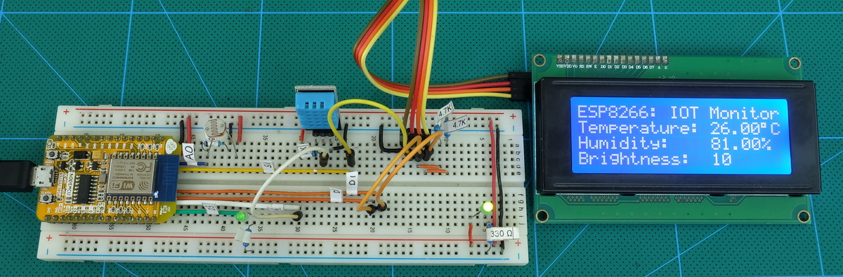
1. Test the sensors with a basic sketch
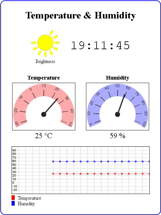
2. Create a basic website using websockets to show the sensor data.
3. Enhance the website, add dials and a graph.
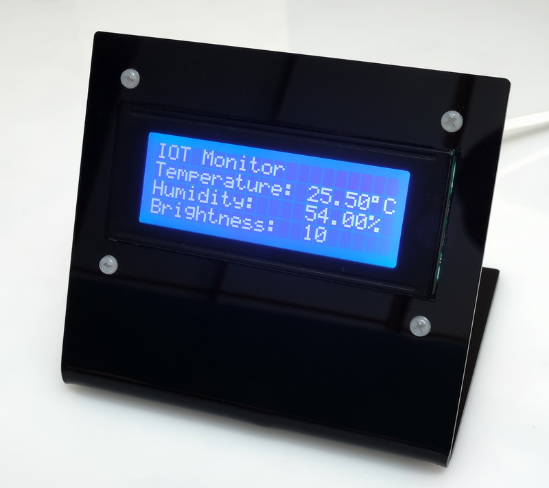
4. Add a LCD
5. Add Wifi Manager.
6. Maybe add time to the LCD version using a NTP server.
7. Put the project in to a stand
Sections 1 to 3 are complete and in this part I want to add a LCD.
We are now ready to implement the final webpage.
 The hard part is the html and javascript for the widgets. The code for the sketch is pretty much the same as in the previous example.
 In the last post we ended with a working but very basic website. Now it’s time to make the webpage look nicer. Be aware that I am not a graphic artist and use the word nicer very loosely.
It’s been a while since my last post on using the ESP8266 with the Arduino IDE. Life became busy and what free time I had I spent updating the dropController. Eventually guilt got the better of me though.
In previous posts we looked at various different things; using the ESP8266 to serve a webpage, using Wifi Manager to create a connect portal, creating a self updating page, using websockets, and more. Now we finally start putting everything together.
In part 8 we set up a self refreshing webpage that displayed the temperature and humidity from a DHT11. In part 9 we took a first look at websockets. In part 10 we combine the two and add a few embellishments.
Websockets can be fast, very fast, and since the webpage will not be updating very often this is not one of the best examples of websockets, it does continue the gentle introduction started last time though.
For a while now I have been wanting to create IOT/web widgets such as graphs and gauges. I wanted widgets similar to the things Blynk offers but I didn’t want the back end server. I wanted every thing self contained on the ESP8266. This project is the start of that.
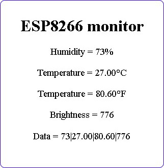
The goal of this guide is to create a environment monitor station that has a LCD display and also a webpage using an ESP8266, a DHT11, a LDR, javascript, and websockets.
As always I will do this is steps so that each part is clear.
A very short post I made sometime ago has been more popular that it should have been. It wasn’t particularly detailed and it was in desperate need of an update. So here is the update, this time giving more details and adding mosfets.
This page has been updated. Please see the following newer guides:
Introduction, Using The Serial Monitor, and More
A Look at the Different Serial Libraries
Serial Commands Explained
Serial Data
Getting Started With Using Serial Communication To Send Commands
ASCII Data and Using Markers to Separate Data
In part 3 we sent and received single characters to control LEDs using a fairly simple technique. If all you need is to remotely turn a few things on and off then this method is probably the best. It is simple, easy to program, and reliable. Sometimes though single characters are not enough and we need to use more complex commands or we may want to send sensor data that comprises more than one character.
In this post I look at a few different techniques for sending complex data and commands; starting with functions that are built in the Arduino language and moving to our own functions that, IMHO, perform better and allow for better code.
This page has been updated. Please see the following newer guides:
Introduction, Using The Serial Monitor, and More
A Look at the Different Serial Libraries
Serial Commands Explained
Serial Data
Getting Started With Using Serial Communication To Send Commands
ASCII Data and Using Markers to Separate Data
In the last post I briefly talked about different data formats and how I recommend keeping things as simple as possible. With this is mind for a first project let’s create a simple blinking LED. We will have one Arduino controlling an LED on a second Arduino. Controls to turn the LED on or off will be sent via serial from the first Arduino to the second Arduino. This is as basic as it gets. Arduino Blink by remote control. The LED has only two states so simple control codes can be used and to start I am using 1 of on and 0 for off.
In these examples I am using Arduino Nanos but any kind of Arduino can be used and for this series I am using Arduino to Arduino communication. The techniques are exactly the same for any UART to UART device. For example, in Arduino to Arduino by Bluetooth I use exactly the same serial communication techniques wirelessly over Bluetooth.
This page has been updated. Please see the following newer guides:
Introduction, Using The Serial Monitor, and More
A Look at the Different Serial Libraries
Serial Commands Explained
Serial Data
Getting Started With Using Serial Communication To Send Commands
ASCII Data and Using Markers to Separate Data
In the previous post I went through the basics of using serial on an Arduino and ran through the different commands. In this post I want to talk about different types of serial data and some of the things you should consider before starting to create code. The type of communication you use or can use will depend largely on the project but there are things that can be considered before starting.
This page has been updated. Please see the following newer guides:
Introduction, Using The Serial Monitor, and More
A Look at the Different Serial Libraries
Serial Commands Explained
Serial Data
Getting Started With Using Serial Communication To Send Commands
ASCII Data and Using Markers to Separate Data
Here we look at using serial communication on the Arduino. Serial UART is one of the various ways an Arduino can communicate with other devices. This includes a host PC and using the Arduino serial monitor is communicating with the PC using serial UART.
Arduino Serial Monitor
End Of Line Characters
Formatting output using the tab command
How fast is serial
Different Arduino Serials
Hardware Serial/Serial
SoftwareSerial
AltSoftSerial
NeoSWSerial
Using a software UART and usb adapter to talk to a PC
Buffer Size
Serial Commands
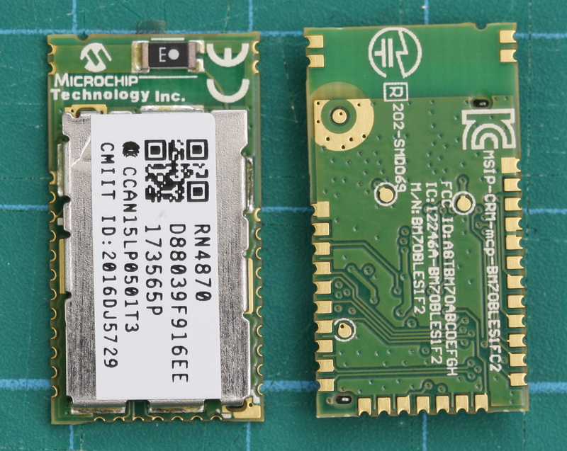 The RN4870/1 is a small (only 12mm wide) BLE module from Microchip. What makes this a little bit special (when compared to modules like the HM-10) are the advanced features that allow you to create your own services and characteristics. This opens up true BLE functionality. It has been available for a while now and I am surprised it is not more popular in the hobby area.
The RN4870 is very different to common hobbyist modules like the HM-10, AT-09, and BT05 and if this is all you have used you may need a refresher on BLE. Especially if you want to use your own services and characteristics.
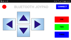 Here we create a basic Classic Bluetooth joypad for use on an Android device to control a microprocessor (Arduino) connected to a Bluetooth module. The app is fairly simply. There are 2 screens; the first is the main control panel and the second is a connection page.
When the CONNECT button on the main screen is clicked the second screen is opened to allow the user to connect to a Bluetooth device. The direction buttons, when clicked, transmit codes to the Arduino.
This guide has been updated. Please jump over to Switching Things On And Off With An Arduino
One of the first projects many people new to the Arduino do is blinking an LED and there many many guides on line. Unfortunately, many of the guides never go beyond the very basic first sketch. In this guide, I hope to help new users take the next step.
Besides the obvious fact that blinking an LED is cool in its own right it is a good exercise because switching an LED on and off is the same process for switching any digital device on and off. Once you can create the code to blink an LED you can create code to turn anything on and off. Of course, you do not need to control an LED, you can use the same methods to do almost anything that is controlled in the same way. For example, I use similar techniques when setting up remote controls using Bluetooth and wifi connections and instead of setting a pin state I send control codes.
Polling vs interrupts
Connecting Arduino pins directly to vcc
Polling. Example 01: Very simply press for on, release for off
Polling. Example 02: Press for on, release for off. Slightly refined
Polling. Example 03: Toggle switch
Polling. Example 04: Multiple states from a single push button switch
Polling. Example 05: Start and stop an action
Part-2-Interrupt-Techniques
Interrupt. Example 01: Turning an LED on and off
Interrupt. Example 02: Turning an LED on and off with debounce
Downloads
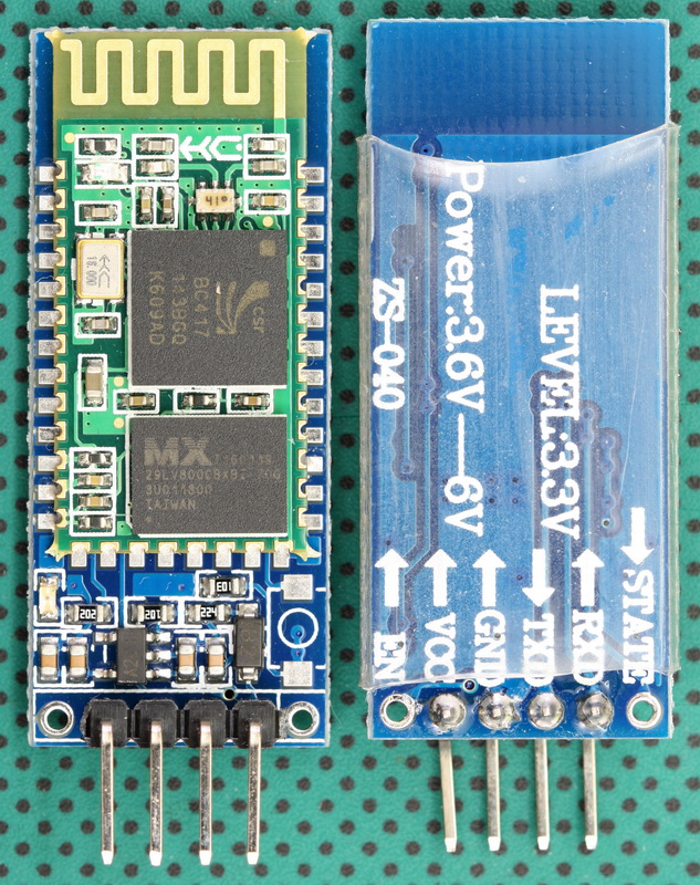
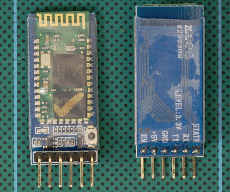 The HC-05 (ZG-B23090W) uses a regular Bluetooth smd module based on the csr BC417 with a MX 29LV800CBXBI-70G flash memory chip. It appears to be using the HC/Wavesen 2010 firmware and a Google search for “HC-05 2.0-20100601” should give you plenty to read, including some of my older posts.
I have received a few comments about HC-06 and HC-05 modules that use a new breakout board (new to me at least). When I received the first comment I hadn’t seen these modules, by the time I had received the 4th or 5th comment the modules were all over Taobao so I decided to order a few (2 x HC-06 and 2 x HC05). I have no real use for these except to see if they are different to previous versions.
HC-05s are Bluetooth 2.0/2.1 EDR devices that have a serial UART layer on top of the Bluetooth. The UART layer makes them easy to use but hides the Bluetooth functions from the user. This is good if all you want is to make 2 things talk to each other. The HC-05 has two modes of operation; AT command mode and transmission mode. When in AT command mode all data received over the serial UART connection is treated as a command, and when in transmission mode, all data received over the serial UART connection is treated as data.
When in communication mode, if there is an active connection the data is broadcast to the connected device. If not connected, the data, disappears in to some mysterious void.
The HC-05 can operate as either a slave or master device. Slave devices cannot initiate connections, they can only accept them. Master devices can initiate and (depending on the actual module) sometimes accept them. If you want to use the module with a mobile device such as an Android phone, the phone will be the master device and so the HC-05 will need to be the slave. If you want to link two HC-05s, one will need to be a master and the other one a slave.
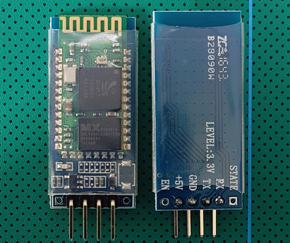 The HC-06 (ZG-B23090W) uses a regular smd Bluetooth module based on the csr BC417 chip with a MX 29LV800CBXBI-70G flash memory chip. The firmware is well documented and a Google search for “HC-06 linvor V1.8” should get you more than a few hits.
I have received a few comments about HC-06 and HC-05 modules that use a new breakout board (new to me at least). When I received the first comment I hadn’t seen these modules, by the time I had received the 4th or 5th comment the modules were all over Taobao so I decided to order a few (2 x HC-06 and 2 x HC05). I have no real use for these except to see if they are different to previous versions.
The HC-06 is a Bluetooth 2.0/2.1 EDR device that has a serial UART layer on top of the Bluetooth. The UART layer makes them extremely easy to use but hides the Bluetooth functions from the user. This is good if all you want is to make 2 things talk to each other.
The HC-06 has 2 modes of operation; AT mode and transmission mode. When the modules are first powered on they go in to AT mode. Here AT commands can be entered via the wired serial connection. After a connection has been made the modules go in to transmission mode. Here everything the modules receives via the wired serial connection is sent to the connected device. At commands cannot be entered again until the connection is broken.
HC-06s are slave only modules and require a master device to make a connection. Slave devices cannot initiate a connection which means you cannot link 2 HC-06s together. The master module is the HC-05 which can be either slave or master. Since the price for the HC-05 and the HC-06 is basically the same I would suggest buying HC-05s and not HC-06s.
Introduction
Arduino Libraries
Parallel Interface: Getting Started with a JHD162A 16×2 display
I2C Interface: Getting Started with a J204A 20×4 display with I2C daughter board
Creating custom characters
HD44780 compatible LCDs come in many shapes and sizes and two very common ones are the 16×2 and 20×4 characters. Although most screens come with a back light some do not. And although the original interface is parallel some screens come with an I2C adapter/daughter board pre attached (you can buy the I2C adapters separately).

There are many types of optocoupler and you chose one based on the requirements of your circuit. My intention was to create a automatic shutter trigger for my Canon camera, so the circuit was a 5V Arduino and a Canon 40D which has about 3.2V on the shutter release connections. Due to the relatively low voltages there are many suitable optocouplers to pick from. I already had a Fairchild 4N26 so this is the one I used.
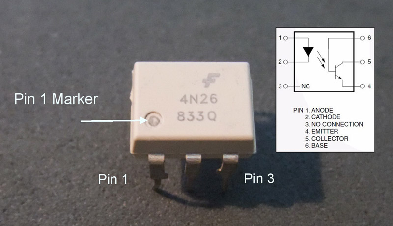
Optocouplers are digital switches. They work by using an LED emitter paired with a photo detector transistor. This means they can be used to allow one circuit to switch a separate circuit without having any electrical contact between the two. Basically, if you put a current through pins 1 and 2 and light the LED the photo detector transistor detects the light from the LED and allows a current to flow through pins 5 and 4. No current on pins 1 and 2 means current does not pass through pins 5 and 4.
A comprehensive look at the HM-10 BLE 4.0 modules.
Using.
Connecting.
Updating.
This page is out-of-date and no longer being updated. For the newer guides jump to the quick links page
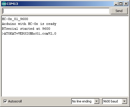
The latest zs-040 HC-06 modules have an updated firmware, hc01.comV2.0. This firmware has the following defaults:
– baud rate = 9600
– password = 1234
– nl/cr line endings not required.
– AT commands are required to be in upper case
– Firmware version = hc01.comV2.0
– Name = HC-06
– No parity
– SLAVE mode
Since the Bluetooth hardware is the same as the previous zs-040 HC-06s the Bluetooth specs are also the same. Bluetooth 2.0 EDR, SSP.
These use a slightly different BT module than the other zs-040 boards and there is a blue LED at the top left of the daughter board.
Updated 12.06.2016: Added example 2
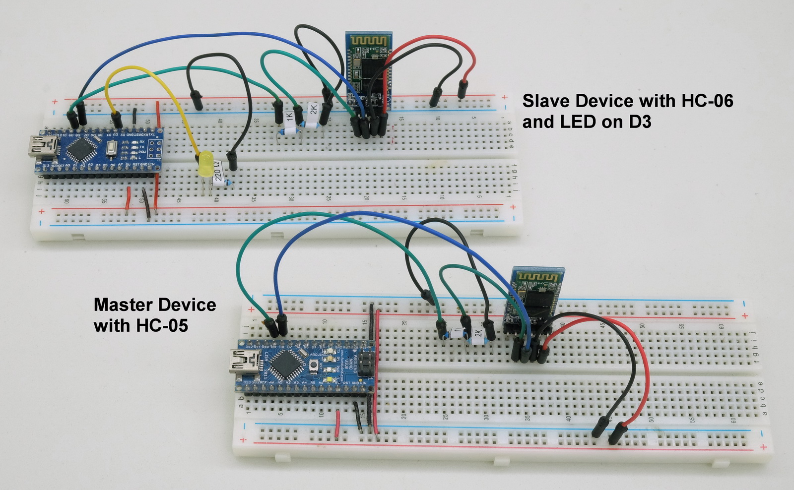
In the Connecting 2 Arduinos by Bluetooth using a HC-05 and a HC-06: Pair, Bind, and Link post I explained how to connect a HC-05 to a HC-06 so that when powered they automatically made a connection. Here we look at using that connection to get Arduinos talking over Bluetooth. Before continuing you need to have the Arduinos and BT modules set up as per the previous post. Here I am using 2 HC-05s. One in master mode the other in slave mode. The setup process for the slave mode HC-05 is the same as the HC-06 in the previous post.
Update 19.09.2015
The FC-114 boards I have have the Bolutek firmware. User DS has reported that he/she has FC-114 boards that have the linvorV1.8 firmware. So if the below does not work for you then check what firmware you have.
I may be missing something but I can not get the HC-05 FC-114 boards in to Master Mode and connect to other BT devices with just AT commands. The modules say they have accepted the commands, such as AT+ROLE1 but when I try to connect to other modules I get the error message “Can only be used in Lord Mode”.
The modules accept “AT+ROLE1” and report they have changed mode but they haven’t really.
In an earlier post I mentioned that it looks likes pin 27 or pin 28 has to be pulled HIGH to enter Master Mode and this does indeed seem to be the case. Everything I have tried without pulling the pin(s) HIGH has failed.
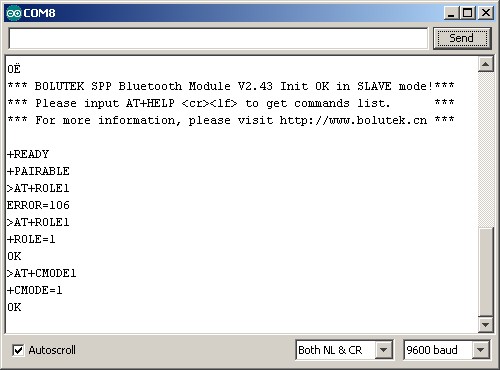
They reply with “OK” and if you interrogate with “AT+ROLE” they report “+ROLE=1” but they are actually still in Slave Mode.
Update 19.09.2015
The FC-114 boards I have have the Bolutek firmware. User DS has reported that he/she has FC-114 boards that have the linvorV1.8 firmware. So if the below does not work for you then check what firmware you have.
Since the HC-05 FC-114s and the HC-06 FC-11s share the same firmware the following should work on either module.
The default setting on start up is Slave Mode waiting for pairing or a connection and also accepting AT commands. This means it is fairly simply to start using AT commands.
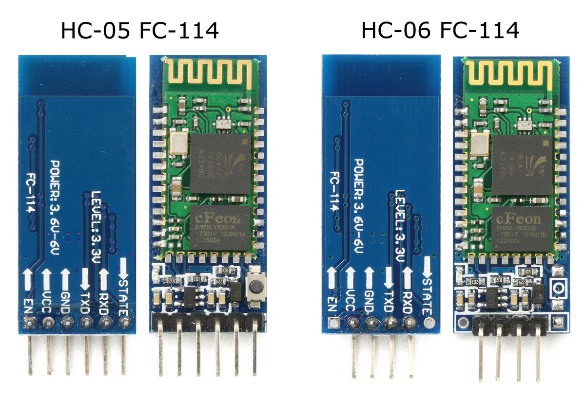
I have just received some new HC-05 and HC-06 Bluetooth modules. These were sold as zs-040s which is the module I actually wanted but I received modules marked FC-114. They share the same breakout board as the zs-040 but have different pins soldered between the Bluetooth module and the breakout board and have a very different firmware.
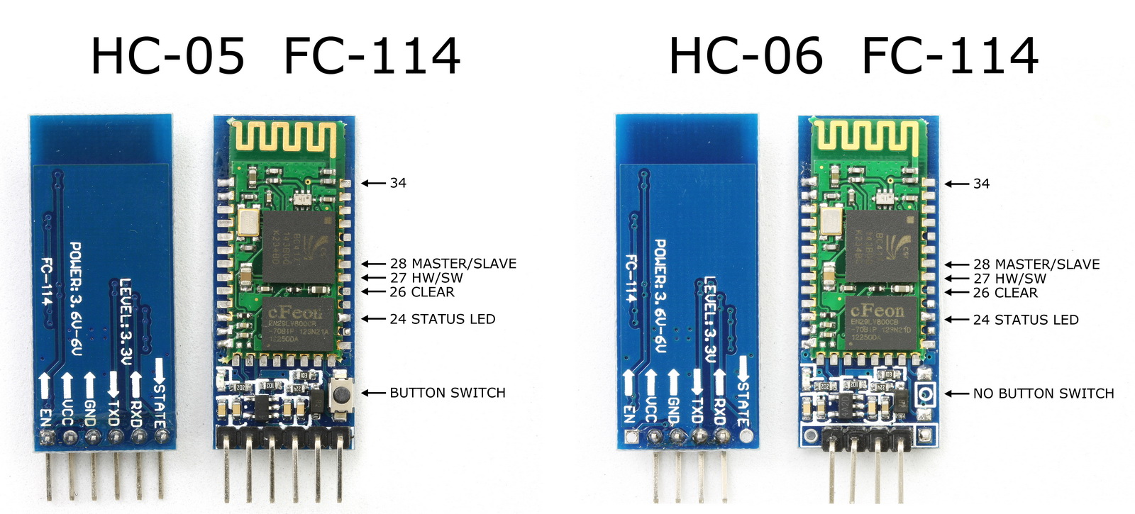
The small push button switch still has traces to pin 34 and still pulls pin 34 HIGH, however, on the FC-114 boards, pin 34 is a regular IO pin and closing the button switch doesn’t do anything. On the zs-040 boards, closing the button switch and pulling pin 34 HIGH puts the modules in to AT mode. Since the FC-114 starts in AT mode this is no big loss.
It took me a while to figure out the differences.
This post follows on from Arduino With HC-05 Bluetooth Module in Slave Mode
The STATE pin on the HC-05 zs050 board is connected to the LED 2 pin on the small bluetooth module and the LED 2 pin is used to indicate when there is an active connection. This means the Arduino can connect to the STATE pin and determine when we have a connection. The STATE pin is LOW when the HC-05 is not connected and HIGH when the HC-05 is connected.
As a quick visual indicator you can put a LED + suitable resistor on the STATE pin. When the module is connected the LED will light.
You can also use the Arduino to read the value of the STATE pin.
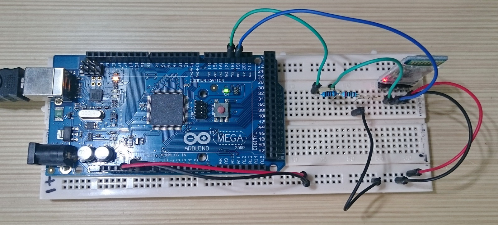
The Arduino Mega has 4 hardware serial channels so we do not need to use software serial, we can use one of the extra hardware serials to talk to the Bluetooth module. In the below example I using serial1 to talk to the HC-05.