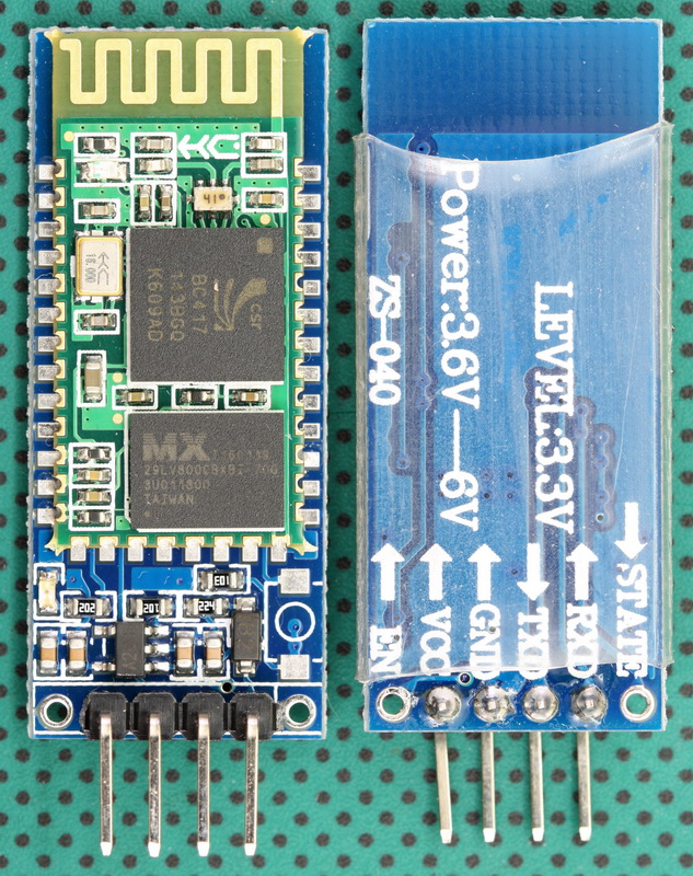
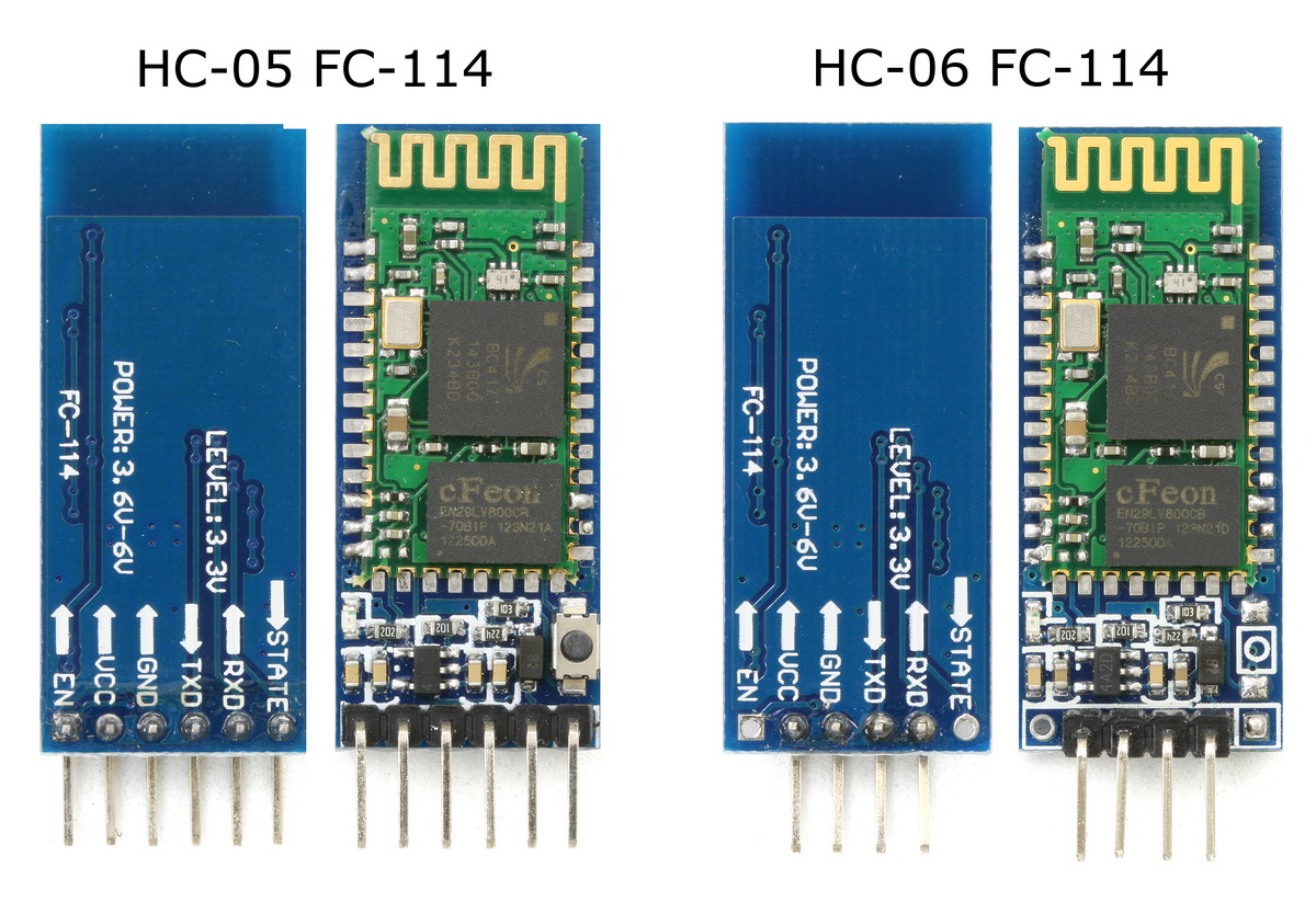
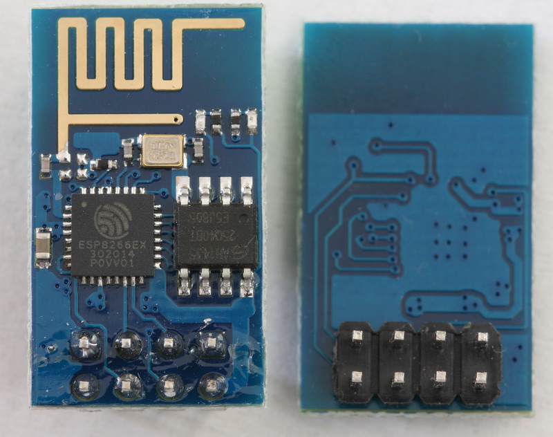
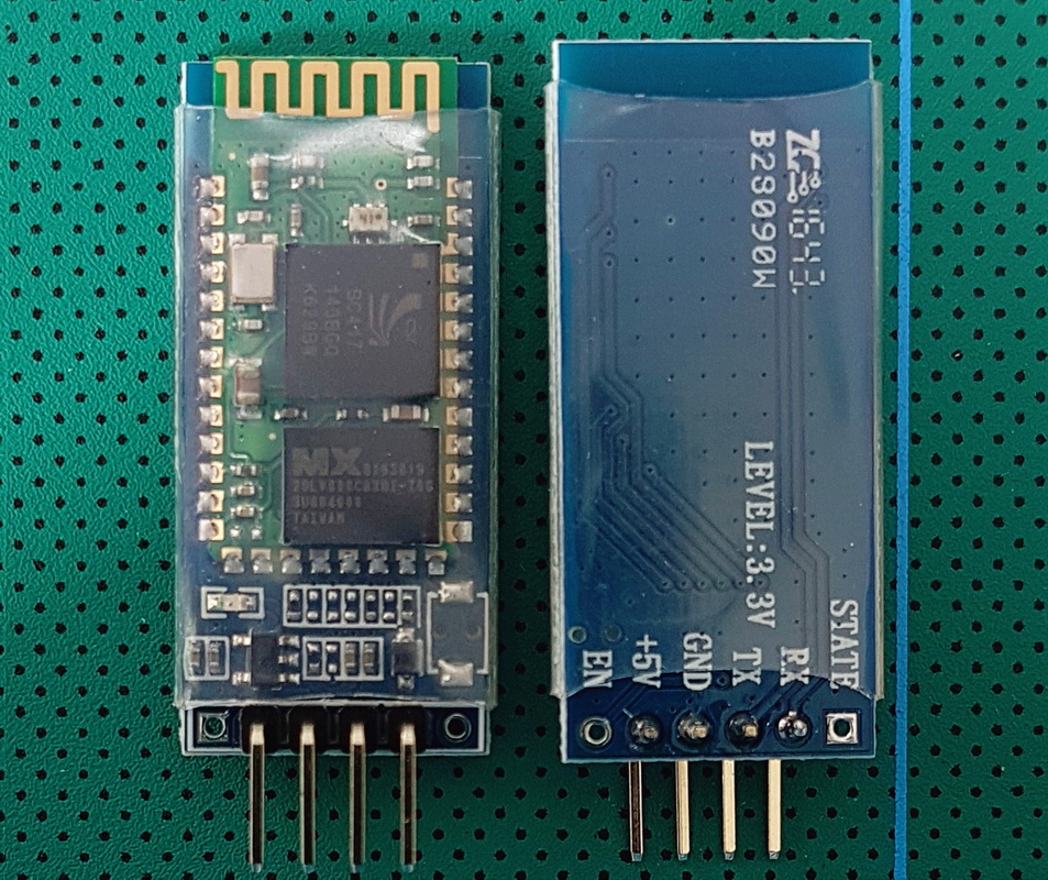
 The HC-06 (ZG-B23090W) uses a regular smd Bluetooth module based on the csr BC417 chip with a MX 29LV800CBXBI-70G flash memory chip. The firmware is well documented and a Google search for “HC-06 linvor V1.8” should get you more than a few hits.
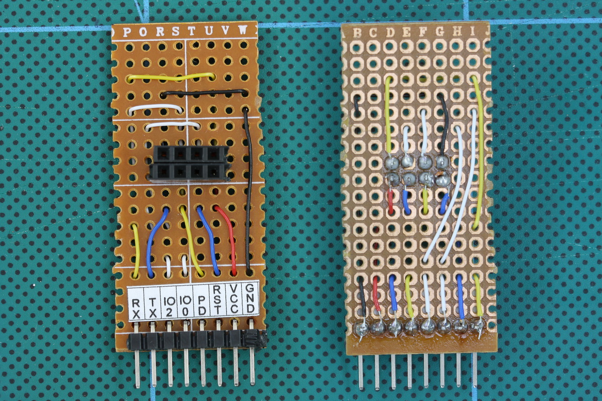
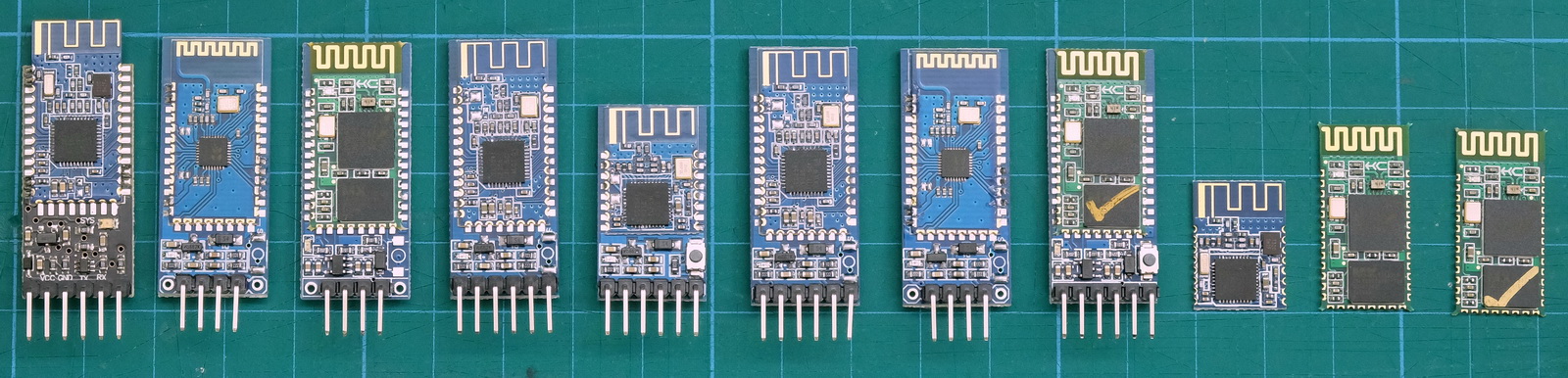
I have received a few comments about HC-06 and HC-05 modules that use a new breakout board (new to me at least). When I received the first comment I hadn’t seen these modules, by the time I had received the 4th or 5th comment the modules were all over Taobao so I decided to order a few (2 x HC-06 and 2 x HC05). I have no real use for these except to see if they are different to previous versions.
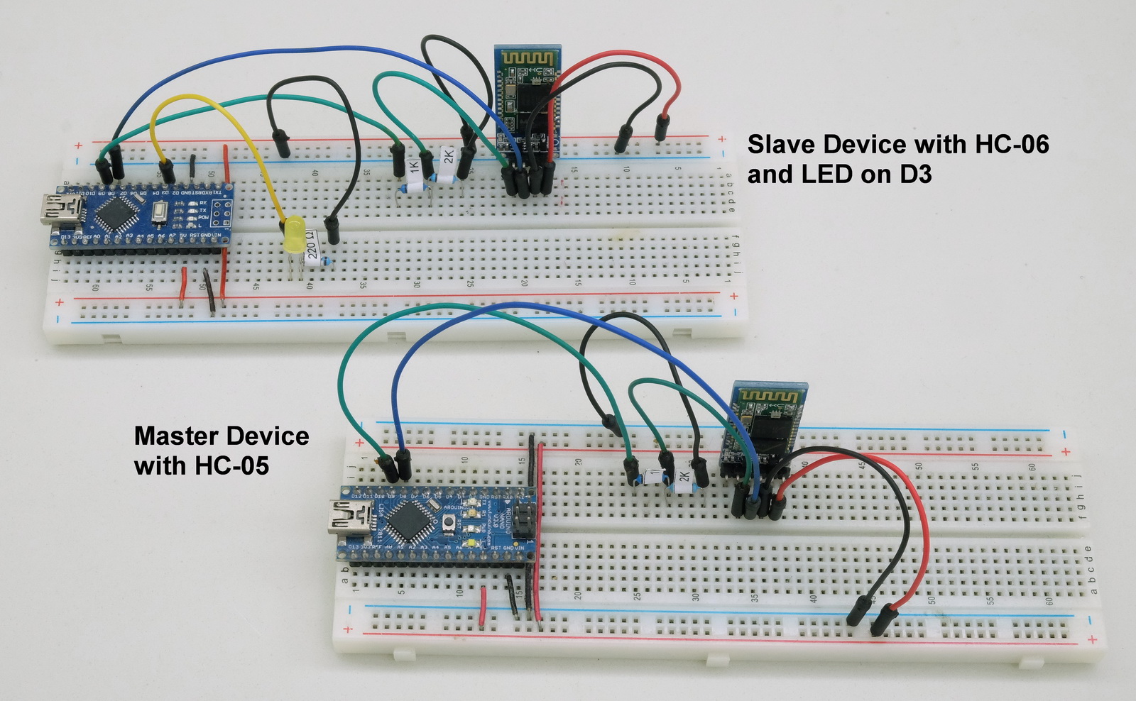
The HC-06 is a Bluetooth 2.0/2.1 EDR device that has a serial UART layer on top of the Bluetooth. The UART layer makes them extremely easy to use but hides the Bluetooth functions from the user. This is good if all you want is to make 2 things talk to each other.
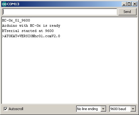
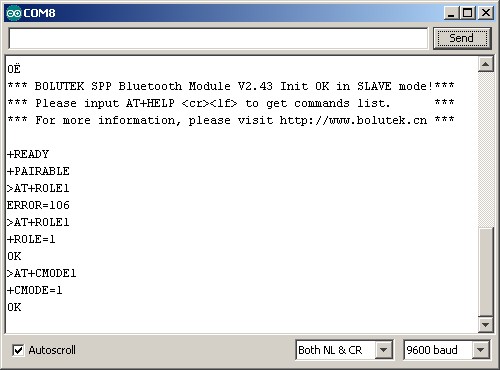
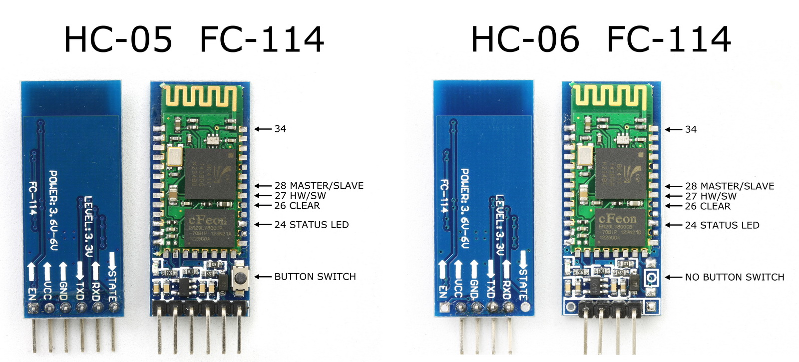
The HC-06 has 2 modes of operation; AT mode and transmission mode. When the modules are first powered on they go in to AT mode. Here AT commands can be entered via the wired serial connection. After a connection has been made the modules go in to transmission mode. Here everything the modules receives via the wired serial connection is sent to the connected device. At commands cannot be entered again until the connection is broken.
HC-06s are slave only modules and require a master device to make a connection. Slave devices cannot initiate a connection which means you cannot link 2 HC-06s together. The master module is the HC-05 which can be either slave or master. Since the price for the HC-05 and the HC-06 is basically the same I would suggest buying HC-05s and not HC-06s.