This page has been updated. Please see the following newer guides:
Introduction, Using The Serial Monitor, and More
A Look at the Different Serial Libraries
Serial Commands Explained
Serial Data
Getting Started With Using Serial Communication To Send Commands
ASCII Data and Using Markers to Separate Data
In part 3 we sent and received single characters to control LEDs using a fairly simple technique. If all you need is to remotely turn a few things on and off then this method is probably the best. It is simple, easy to program, and reliable. Sometimes though single characters are not enough and we need to use more complex commands or we may want to send sensor data that comprises more than one character.
In this post I look at a few different techniques for sending complex data and commands; starting with functions that are built in the Arduino language and moving to our own functions that, IMHO, perform better and allow for better code.
Multiple Characters
A common mistake a lot of beginners make is to test data before they have it. When receiving more than one character via serial, it is easy to assume that all the data arrives at one time. It does not. When a device sends “HELLO” it is sent one character at a time and received one character at a time. The receiving device then has to put all the characters together to form the word “HELLO”. By Arduino standards serial is very slow and the Arduino is capable of performing thousands of tasks in the time it takes to receive all the characters. This means if you are not careful your code can start checking the received data before you have actually received it.
Another problem I have seen is thinking a serial.read reads all the available data. It doesn’t. It reads one character or byte only and it is up to you to read all the data and put it together.
Serial.readBytesUntil(…)
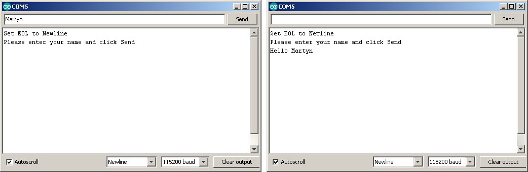
Let’s start with a simple example of receiving strings from the serial monitor. Here the user types in their name and clicks send. The Arduino does not know the length of the users name so we need a way of determining that we have all the data. A fairly simple method is to use Serial.readBytesUntil(…) this allows us to use a terminating character as a marker.
If you read part 1, you may remember that Serial.readBytesUntil(..) reads from the serial buffer until 1 of 3 conditions occur:
1 – it finds the terminating character
2 – it has read the specified number of characters
3 – it times out.
![]()
In the serial monitor we can choose what EOL characters are added to the input. Here I am using Newline only. This adds a newline (“\n”) to the input and we can use this in the Serial.readBytesUntil(..) function as the terminating character. “\n” has the decimal value of 10.
// Arduino_Serial_Part_4_001_Serial_input int length = 30; char buffer [31]; char termChar = '\n'; void setup() { Serial.begin(115200); Serial.println("Set line endings Newline"); Serial.println(""); Serial.println("Please enter your name and click Send"); } void loop() { if (Serial.available()) { int numChars = Serial.readBytesUntil(termChar, buffer, length); buffer[numChars]='\0'; Serial.print("Hello "); Serial.println(buffer); } } |
This is very basic and does not include any error trapping. The buffer is set to a maximum length of 30 characters but it is possible for the user to enter more than this. This would probably cause the sketch to misbehave.
Give the above a try. It should work quite well as long as you remember the limitations.

What happens if you do not enter the newline character? Give it a try. Select “No line Ending” in the serial monitor and enter a new name. It still works but there is a delay before the Arduino responds. This is because the Serial.readBytesUntil(..) function is waiting until it times out. The default timeout is 1000ms or 1 second, so the delay should be 1 second. For this example a 1 second delay is not a big deal but it could be a problem if the data is not being transmitted quick enough. The function would time out before receiving all the data. Select no line endings and try entering your name slowly one character at a time. Click send after each letter. The chances are your name will appear in parts.
Function to read serial until a terminating character
Unless you are very careful with how you implement your code it is likely the Serial.readBytesUntil(..) timeout will cause problems. We could increase the timeout, this would kind of work, but remember the function blocks while waiting. This means the Arduino cannot do anything else. A better way may be to create our own function that collects the serial input, with no timeout, while still doing other things.
// Arduino_Serial_Part_4_002_Serial_input char c = ' '; int length = 30; char buffer [31]; char termChar = 10; byte index = 0; void setup() { Serial.begin(115200); Serial.println("Set EOL to Newline"); Serial.println("Please enter your name and click Send"); } void loop() { if (Serial.available()) { c = Serial.read(); if (c != termChar) { buffer[index] = c; index = index + 1; } else { buffer[index] = '\0'; index = 0; processNewData(); } } } void processNewData() { Serial.print("Hello "); Serial.println(buffer); } |
You should be able to see that on every iteration of the loop serial is checked for data. If there is data a single character/byte is read. The newly read character is checked to see if it is the terminating character. If it is it means we have new data. If not, the character just read is added to the char array called buffer and the process continues. If the last character read is the terminating character then we do something with the new data.
You should also be able to see that we are not waiting for data to arrive. We check for new data and if there is some we deal with it. If no new data we continue. This means we can do other things rather than sitting around waiting for all the serial data to arrive.
The sketch works but is not really easy to develop. Let’s tidy up the sketch and put the main parts in to their own functions.
// Arduino_Serial_Part_4_003_Serial_input char c = ' '; int length = 30; char buffer [31]; char termChar = 10; byte index = 0; boolean haveNewData = false; void setup() { Serial.begin(115200); Serial.println("Set EOL to Newline"); Serial.println("Please enter your name and click Send"); } void loop() { readSerial(); if ( haveNewData ) { processNewData(); } } void readSerial() { if (Serial.available()) { c = Serial.read(); if (c != termChar) { buffer[index] = c; index = index + 1; } else { buffer[index] = '\0'; index = 0; haveNewData = true; } } } void processNewData() { Serial.print("Hello "); Serial.println(buffer); haveNewData = false; } |
This does exactly the same and is far easier to read the code. All we have in the main loop is
readSerial(); if ( haveNewData ) { processNewData(); } |
which makes adding more code a lot easier.
Code explanation
Variable c is used to store the latest character read from the serial input buffer
Variable length is the maximum length of the buffer
Variable buffer is a char array used to store the incoming data
Variable termChar is the terminating character
Variable index is the index position of the buffer. Where the next character should be copied to.
Variable haveNewData is a flag used to tell the rest of the sketch when we have new data.
if (Serial.available()) { c = Serial.read(); if (c != termChar) { buffer[index] = c; index = index + 1; } |
If serial data is available we read one character in to c. We then check to see if c is not the terminating character and if it is not we copy c to the buffer char array at position specified by index. Then index is incremented ready for the next character.
else { buffer[index] = '\0'; index = 0; haveNewData = true; } |
If c is the terminating character there is no need to copy it to the buffer we simply close the buffer (add ‘\0’ to the end of the buffer) set index to 0 ready for next time and set haveNewData = true to show we have new data.
In the main loop we check to see if haveNewData is set and if it is call the processData() function. As well as handling the new data processData() function also resets haveNewData.
Give it a try. It should be exactly the same as before.
Why is this better than using Serial.readBytesUntil(…)?
As mentioned above, Serial.readBytesUntil(…) has a timeout. This is unlikely to be an issue when using the serial monitor but it becomes an issue when receiving serial data from other devices. Our new method does not have a time limit. It can receive one character a minute, or one character an hour and still work fine. You can test this yourself using the serial monitor. Set the EOL to “No line ending”, enter A click send, enter B, click send, enter C and click send. Now change the EOL back to “Newline”, enter D and click send. “ABCD” should appear in the serial monitor.
Things to be aware of
1 – It is still possible to receive more data than the buffer can hold.
2 – We do not know if we received the very start of the data. We only know we received the end.
There is no 100% satisfactory way around issue #1 while using a buffer. The Arduino does not have the memory to handle very large buffers and we can’t simply keep making the buffer bigger (a bit bigger is OK depending on the size of the rest of the sketch). Although the sketch may not be able to handle large data sets we can at least stop the large data corrupting the Arduino memory. Unfortunately doing so means we can loose data.
If you do need to handle large blocks of data you would manage the data as it arrives rather than saving it to a buffer.
Issue #2 we address a little later
Limiting received data to the size of the buffer
To limit the size all we need to do is check the current index position against the maximum size of the buffer. If we have reached the end of the buffer do not increase the index. This does mean the end of the data will be missing but at least the sketch is not going to go down in flames.
Char array over runs are very difficult and annoying to debug. The Arduino will quite happily try to copy 40 or 50 characters in to a 30 character char array which can cause all sorts of mayhem. The memory directly after the char array is likely used by other variables so when you over run the array size you start over writing other variables.
All we need to do it add the following
if (index < length) { buffer[index] = c; index = index + 1; } |
and our final sketch is
// Arduino_Serial_Part_4_004_Serial_input char c = ' '; int length = 30; char buffer [31]; char termChar = 10; byte index = 0; boolean haveNewData = false; void setup() { Serial.begin(115200); Serial.println("Set EOL to Newline"); Serial.println("Please enter your name and click Send"); } void loop() { readSerial(); if ( haveNewData ) { processNewData(); } } void readSerial() { if (Serial.available()) { c = Serial.read(); if (c != termChar) { if (index < length) { buffer[index] = c; index = index + 1; } } else { buffer[index] = '\0'; index = 0; haveNewData = true; } } } void processNewData() { Serial.print("Hello "); Serial.println(buffer); haveNewData = false; } |
If you allow the Arduino time to get started and ensure that serial has started the above can be fairly reliable. It could be a little more foolproof and we cannot be 100% sure we have received the start of the data only the end. To address this, the next step is to use a start marker as well as an end marker.
Serial Arduino to Arduino using an End Marker
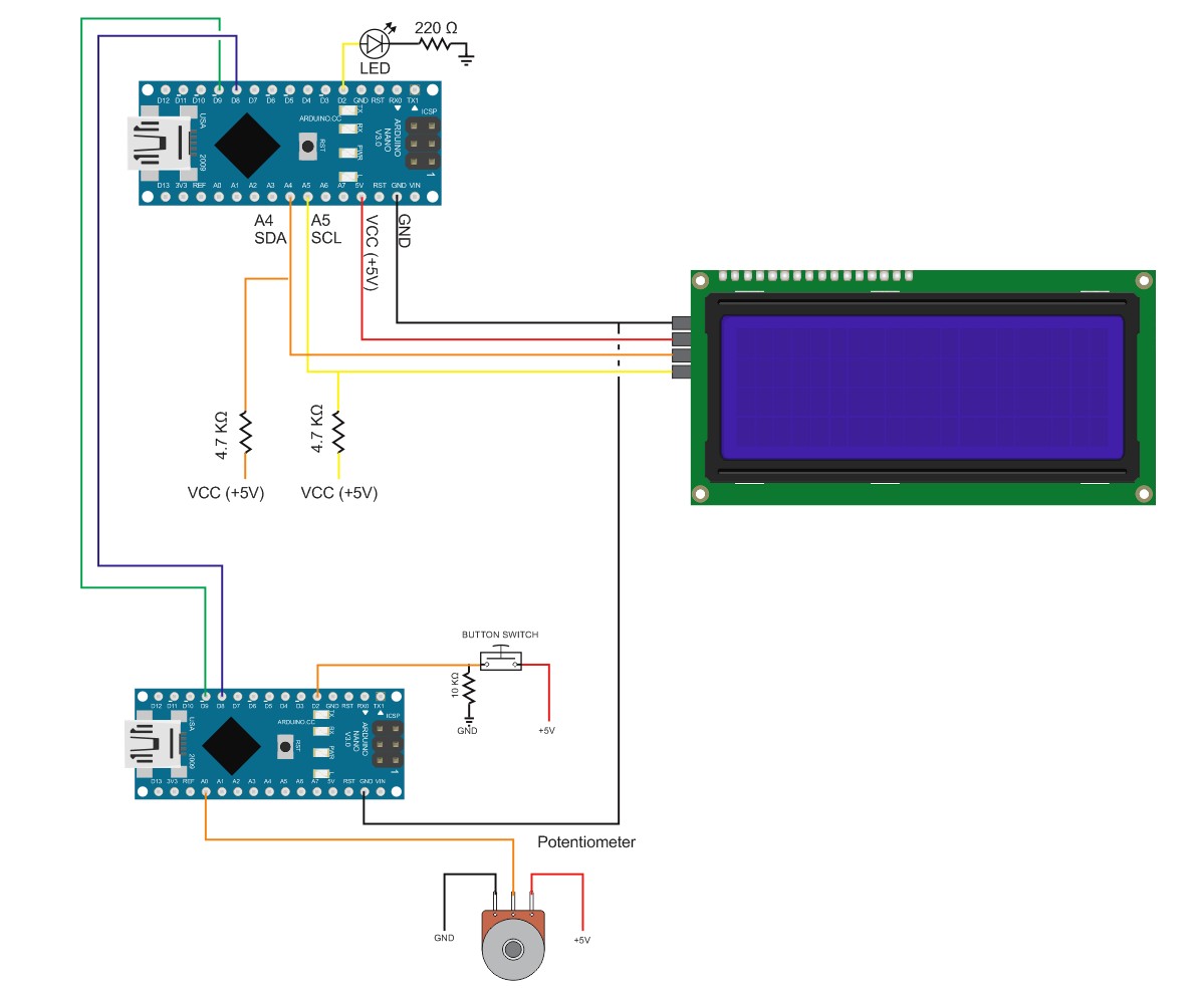
Playing with the serial monitor is all well and good but it is not very practical. Here is an example of sending a sensor reading to another Arduino that displays the sensor value on an LCD screen.
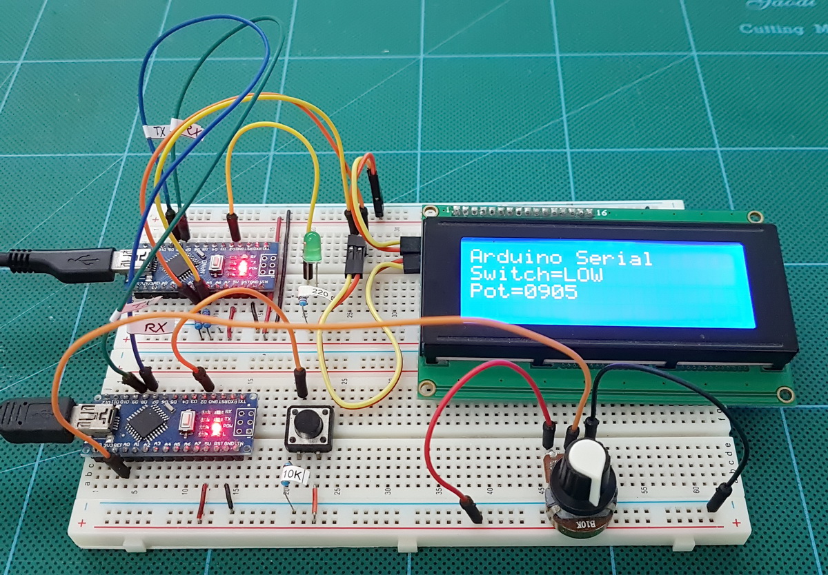
(The green LED doesn’t do anything. It is used in another circuit later and I forgot to remove it.)
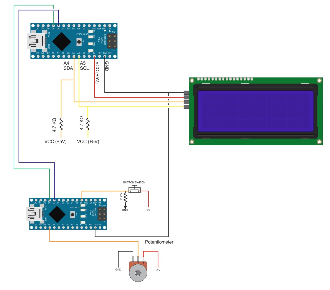
In this example both Arduinos are connected to the same computer. This means their GNDs are connected through the USB connection and I did not need to add on the breadboard. When the Arduinos have separate power supplies the GNDs need to be connected.
The following sketches use AltSoftSerial and NewliquidCrystal.
For more information on LCDs screens and the NewliquidCrystal library see Arduino with HD44780 based Character LCDs
For more information on AltSoftSerial see part 1
The master device has a button switch and a potentiometer. The sketch reads the status of these devices and sends the reading to the slave device using AltSoftSerial. The slave device receives the data and displays it on the LCD screen.
Arduino_Serial_Using_EOL_Master
// Arduino_Serial_Using_EOL_Master #include <AltSoftSerial.h> AltSoftSerial ALTserial; byte switchPin = 2; // input pin for the switch boolean newSwitchState1 = LOW; // used for simple debouce boolean newSwitchState2 = LOW; boolean newSwitchState3 = LOW; boolean oldSwitchState = LOW; // variable to hold the switch state int potPin = A0; // input pin for the potentiometer int val = 0; // variable to store the value coming from the pot int oldval = 0; // variable to store the old pot value unsigned long startTime = 0; unsigned long nowTime = 0; unsigned long waitTime = 500; void setup() { Serial.begin(9600); Serial.println("Press the button switch or twiddle the pot."); ALTserial.begin(9600); pinMode(switchPin, INPUT); startTime = millis(); } void loop() { newSwitchState1 = digitalRead(switchPin); delay(1); newSwitchState2 = digitalRead(switchPin); delay(1); newSwitchState3 = digitalRead(switchPin); // Simple debouce - if all 3 values are the same we can continue if ( (newSwitchState1==newSwitchState2) && (newSwitchState1==newSwitchState3) ) { // only interested if the switch has changed state. HIGH to LOW or LOW to HIGH if ( newSwitchState1 != oldSwitchState ) { oldSwitchState = newSwitchState1; // has the button switch been closed? if ( newSwitchState1 == HIGH ) { Serial.println("S=HIGH"); ALTserial.print("S=HIGH\n"); } else { Serial.println("S=LOW"); ALTserial.print("S=LOW\n"); } } } // only want to check the pot every 500 ms // and only want to send if the value has changed nowTime = millis(); if (nowTime - startTime > waitTime) { startTime = nowTime; val = analogRead(potPin); if ((val) != (oldval) ) { oldval = val; Serial.print("P="); HS_printFixedFormat(val); Serial.print("\r\n"); ALTserial.print("P="); ALT_printFixedFormat(val); ALTserial.print("\n"); } } } void ALT_printFixedFormat(int num) { if (num <1000) { ALTserial.print("0"); } if (num <100) { ALTserial.print("0"); } if (num <10) { ALTserial.print("0"); } ALTserial.print(num); } void HS_printFixedFormat(int num) { if (num <1000) { Serial.print("0"); } if (num <100) { Serial.print("0"); } if (num <10) { Serial.print("0"); } Serial.print(num); } |
The master sketch reads the button switch every loop and when a change is detected it reacts straight away. The sketch reads the potentiometer every half second. Checks to see if the value has changed and only if the value has changed does it send the reading to the slave Arduino. Only sending data if the reading has changed reduces the amount of serial data that needs sending.
I am using a fixed length value for the potentiometer. ALT_printFixedFormat() adds leading zeros to pad the number. 1 becomes “0001” and 999 becomes “0999”
void ALT_printFixedFormat(int num) { if (num <1000) { ALTserial.print("0"); } if (num <100) { ALTserial.print("0"); } if (num <10) { ALTserial.print("0"); } ALTserial.print(num); } |
You can test the master sketch by opening the serial monitor. Everything sent to the AlrSoftSerial connection is copied to the hardware serial. This is good for monitoring and debugging but not actually required.
Arduino_Serial_Using_EOL_Slave
// Arduino_Serial_Using_EOL_Slave #include <AltSoftSerial.h> AltSoftSerial ALTserial; #include <Wire.h> #include <LiquidCrystal_I2C.h> //LiquidCrystal_I2C lcd(0x27, 2, 1, 0, 4, 5, 6, 7, 3, POSITIVE); // Set the pins on the I2C chip used for LCD connections: // addr, en,rw,rs,d4,d5,d6,d7,bl,blpol LiquidCrystal_I2C lcd(0x27, 2, 1, 0, 4, 5, 6, 7, 3, POSITIVE); // Set the LCD I2C address char c; int length = 30; char buffer [31]; char termChar = '\n'; byte index = 0; boolean haveNewData = false; void setup() { Serial.begin(9600); Serial.println("Ready"); ALTserial.begin(9600); lcd.begin(20, 4); lcd.setCursor(0, 0); lcd.print("Arduino Serial"); lcd.setCursor(0, 1); lcd.print("Switch="); lcd.setCursor(0, 2); lcd.print("Pot="); } void loop() { readSerial(); if ( haveNewData ) { processNewData(); } } void readSerial() { if (ALTserial.available()) { c = ALTserial.read(); if (c != termChar) { if (index < length) { buffer[index] = c; index = index + 1; } } else { buffer[index] = '\0'; index = 0; haveNewData = true; } } } void processNewData() { Serial.println(buffer); if (buffer[0] == 'S') { lcd.setCursor(7, 1); if (buffer[2] == 'H') { lcd.print("HIGH"); } if (buffer[2] == 'L') { lcd.print("LOW "); } } if (buffer[0] == 'P') { lcd.setCursor(4, 2); char temp[5]; temp[0] = buffer[2]; temp[1] = buffer[3]; temp[2] = buffer[4]; temp[3] = buffer[5]; temp[4] = '\0' ; lcd.print( temp); } haveNewData = false; buffer[0] = '\0'; } |
The slave sketch is very similar to the Arduino_Serial_Part_4_004_Serial_input example above. The difference is in the processNewData() function. In the new sketch, if the received data is a switch reading (starts with a “S”) the sketch shows HIGH or LOW on the LCD. If the reading is a pot reading (starts with a “P”), it shows the pot value on the screen.
When processing the button switch data, you should see that I do not check the whole command, only the first letter (H and L). This means I do not actually need the whole command and could use “S=H” and “S=L”. I do not use the “=” either so this can be removed and the commands could be “SH” and “SL”. I am not concerned about speed here and “S=HIGH” and “S=LOW” are easier to read when you are reviewing the code but if performance is a priority you should keep the amount of data transmitted as low as possible.
Using AltSoftSerial you should be able to increase the baud rate to 38400 bps without any issues. Beyond this you may start to notice problems. It is worth experimenting with higher baud rates to see how far you can take it.
An issue worth mentioning is additional EOL characters. The standard Arduino EOL is 2 characters “\n” and “\r” which are added to the end of the line in that order. This means if you use the above method and the data has normal EOL charters, the function will leave the “\r” character in the serial buffer which then gets added to the start of the next data. This will cause issues with formatting and converting ascii to values and very likely be difficult to debug.
Serial Arduino to Arduino Using Start and End Markers
Start and end markers is my preferred method for serial data when speed is not a priority. To make things a little easier on myself I also use ascii for numbers and try to use fixed length data wherever possible. You can see more examples here and here.
Start and end markers is not original and is based on (or simply copied) from a post by Robin2 on the Arduino forum. I started using this function a while ago, liked it and have used it ever since.
Robin2’s function
void recvWithStartEndMarkers() { static boolean recvInProgress = false; static byte ndx = 0; char startMarker = '['; char endMarker = ']'; char rc; if (Serial.available() > 0) { rc = Serial.read(); if (recvInProgress == true) { if (rc != endMarker) { receivedChars[ndx] = rc; ndx++; if (ndx > maxDataLength) { ndx = maxDataLength; } } else { receivedChars[ndx] = '\0'; // terminate the string recvInProgress = false; ndx = 0; newData = true; } } else if (rc == startMarker) { recvInProgress = true; } } } |
I use square brackets ([ and ]) as start and end markers. The function reads the serial input buffer until it finds a start marker, it then starts to copy data to the buffer called receivedChars. When it finds the end marker it stops copying and sets newData true. Anything not inside the markers is ignored.
Give it a try
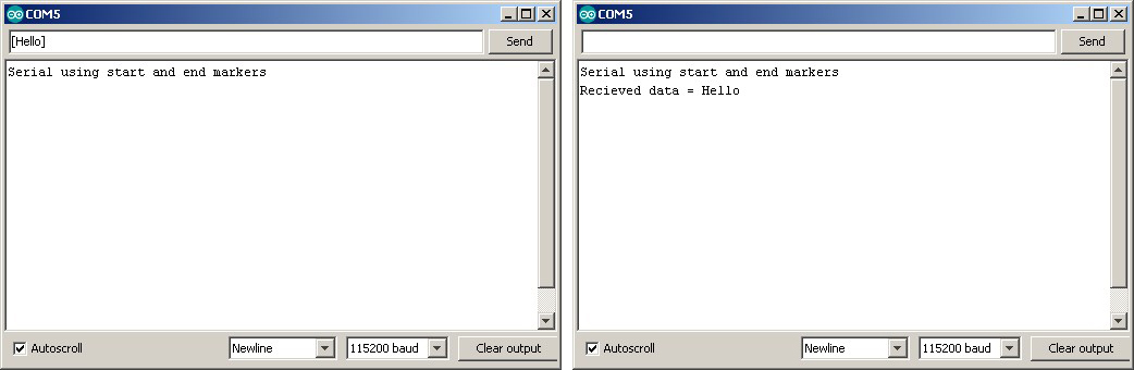
Upload the following sketch, open the serial monitor and enter something. If you use the start and end markers, what ever is contained in the markers will be displayed in the serial monitor. Anything outside the markers will be ignored.
// Arduino_Serial_Part_4_005_SerialMonitor_input const byte maxDataLength = 30; // maxDataLength is the maximum length allowed for received data. char receivedChars[31] ; boolean newData = false; // newData is used to determine if there is a new command void setup() { Serial.begin(115200); Serial.println("Serial using start and end markers"); newData = false; } void loop() { recvWithStartEndMarkers(); // check to see if we have received any new commands if (newData) { processCommand(); } // if we have a new command do something } void processCommand() { Serial.print("Recieved data = "); Serial.println(receivedChars); newData = false; } // function recvWithStartEndMarkers by Robin2 of the Arduino forums // See http://forum.arduino.cc/index.php?topic=288234.0 void recvWithStartEndMarkers() { static boolean recvInProgress = false; static byte ndx = 0; char startMarker = '['; char endMarker = ']'; if (Serial.available() > 0) { char rc = Serial.read(); if (recvInProgress == true) { if (rc != endMarker) { if (ndx < maxDataLength) { receivedChars[ndx] = rc; ndx++; } } else { receivedChars[ndx] = '\0'; // terminate the string recvInProgress = false; ndx = 0; newData = true; } } else if (rc == startMarker) { recvInProgress = true; } } } |
In the serial monitor enter “[hello]”
Now try entering “This will be ignored[This will be processed]”
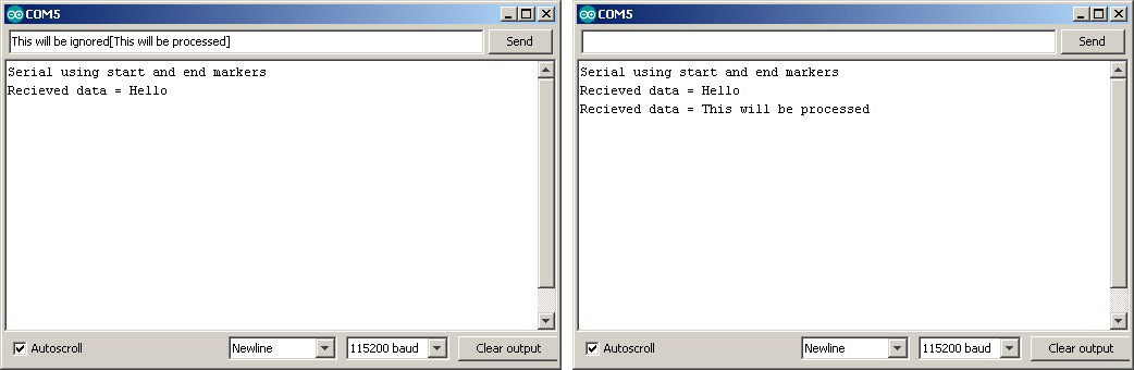
The data outside of the start and end markers is ignored.
The only drawback to this method is that the data cannot contain the start and end markers without using special techniques like control codes. You can off course use any value or character for the markers.
Let’s adapt the EOL example to use start and end markers
Arduino_Serial_Using_StartAndEndMarkers_Master
// Arduino_Serial_Using_StartAndEndMarkers_Master #include <AltSoftSerial.h> AltSoftSerial ALTserial; byte switchPin = 2; // input pin for the switch boolean newSwitchState1 = LOW; // used for simple debouce boolean newSwitchState2 = LOW; boolean newSwitchState3 = LOW; boolean oldSwitchState = LOW; // variable to hold the switch state int potPin = A0; // input pin for the potentiometer int val = 0; // variable to store the value coming from the pot int oldval = 0; // variable to store the old pot value unsigned long startTime = 0; unsigned long nowTime = 0; unsigned long waitTime = 500; void setup() { Serial.begin(9600); Serial.println("Press the button switch or twiddle the pot."); ALTserial.begin(9600); pinMode(switchPin, INPUT); startTime = millis(); } void loop() { newSwitchState1 = digitalRead(switchPin); delay(1); newSwitchState2 = digitalRead(switchPin); delay(1); newSwitchState3 = digitalRead(switchPin); // Simple debouce - if all 3 values are the same we can continue if ( (newSwitchState1==newSwitchState2) && (newSwitchState1==newSwitchState3) ) { // only interested if the switch has changed state. HIGH to LOW or LOW to HIGH if ( newSwitchState1 != oldSwitchState ) { oldSwitchState = newSwitchState1; // has the button switch been closed? if ( newSwitchState1 == HIGH ) { Serial.println("[S=HIGH]"); ALTserial.print("[S=HIGH]"); } else { Serial.println("[S=LOW]"); ALTserial.print("[S=LOW]"); } } } // only want to check the pot every 500 ms (change this if you like) // and only want to send if the value has changed nowTime = millis(); if (nowTime - startTime > waitTime) { startTime = nowTime; val = analogRead(potPin); if ((val) != (oldval) ) { oldval = val; Serial.print("[P="); HS_printFixedFormat(val); Serial.println("]"); ALTserial.print("[P="); ALT_printFixedFormat(val); ALTserial.print("]"); } } } void ALT_printFixedFormat(int num) { if (num <1000) { ALTserial.print("0"); } if (num <100) { ALTserial.print("0"); } if (num <10) { ALTserial.print("0"); } ALTserial.print(num); } void HS_printFixedFormat(int num) { if (num <1000) { Serial.print("0"); } if (num <100) { Serial.print("0"); } if (num <10) { Serial.print("0"); } Serial.print(num); } |
Arduino_Serial_Using_StartAndEndMarkers_Slave
// Arduino_Serial_Using_StartAndEndMarkers_Slave #include <AltSoftSerial.h> AltSoftSerial ALTserial; #include <Wire.h> #include <LiquidCrystal_I2C.h> //LiquidCrystal_I2C lcd(0x27, 2, 1, 0, 4, 5, 6, 7, 3, POSITIVE); // Set the pins on the I2C chip used for LCD connections: // addr, en,rw,rs,d4,d5,d6,d7,bl,blpol LiquidCrystal_I2C lcd(0x27, 2, 1, 0, 4, 5, 6, 7, 3, POSITIVE); // Set the LCD I2C address char c; int length = 30; char buffer [31]; boolean haveNewData = false; void setup() { Serial.begin(9600); Serial.println("Ready"); ALTserial.begin(9600); lcd.begin(20, 4); lcd.setCursor(0, 0); lcd.print("Arduino Serial"); lcd.setCursor(0, 1); lcd.print("Switch="); lcd.setCursor(0, 2); lcd.print("Pot="); } void loop() { recvWithStartEndMarkers(); if ( haveNewData ) { processNewData(); } } void recvWithStartEndMarkers() { static boolean recvInProgress = false; static byte ndx = 0; char startMarker = '['; char endMarker = ']'; char rc; if (ALTserial.available() > 0) { rc = ALTserial.read(); if (recvInProgress == true) { if (rc != endMarker) { buffer[ndx] = rc; ndx++; if (ndx > length) { ndx = length; } } else { buffer[ndx] = '\0'; // terminate the string recvInProgress = false; ndx = 0; haveNewData = true; } } else if (rc == startMarker) { recvInProgress = true; } } } void processNewData() { Serial.println(buffer); if (buffer[0] == 'S') { lcd.setCursor(7, 1); if (buffer[2] == 'H') { lcd.print("HIGH"); } if (buffer[2] == 'L') { lcd.print("LOW "); } } if (buffer[0] == 'P') { lcd.setCursor(4, 2); char temp[5]; temp[0] = buffer[2]; temp[1] = buffer[3]; temp[2] = buffer[4]; temp[3] = buffer[5]; temp[4] = '\0' ; lcd.print( temp); } haveNewData = false; buffer[0] = '\0'; } |
The sketches do exactly the same as in the previous example. The only difference we are now using start and end markers
In the master sketch start and end markers have been added to the data
ALTserial.print("[S=HIGH]"); ... ALTserial.print("[S=LOW]"); |
and in the slave sketch the recvWithStartEndMarkers() function replaces the readSerial(). Everything else is the same.
Advanced example. Non blocking Serial
I mentioned above that one of the benefits of using your own functions rather than those built in to the Arduino core is that with your own functions the Arduino can do other things while still receiving serial data. Using the functions from the Arduino core, such as readBytesUntil() block the Arduino.
To show how not blocking may be useful, the next example adds a flashing LED. When the pot value goes above a certain level the LED starts to flash. The master sketch remains the same as above. The slave sketch is updated to include the new code (which is very similar to the potentiometer timing check code used in the master sketch).
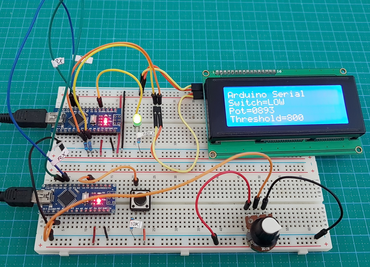
When the pot value is below the threshold the LED is off.
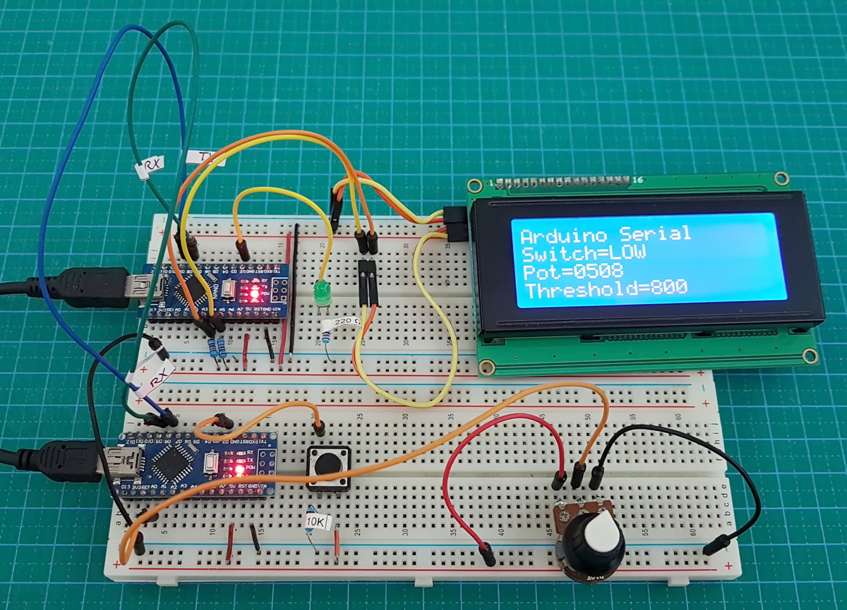
When the pot value goes above the threshold the LED starts to flash.
Arduino_Serial_Using_StartAndEndMarkers_Slave_flashingLED
// Arduino_Serial_Using_StartAndEndMarkers_Slave_flashingLED #include <AltSoftSerial.h> AltSoftSerial ALTserial; #include <Wire.h> #include <LiquidCrystal_I2C.h> //LiquidCrystal_I2C lcd(0x27, 2, 1, 0, 4, 5, 6, 7, 3, POSITIVE); // Set the pins on the I2C chip used for LCD connections: // addr, en,rw,rs,d4,d5,d6,d7,bl,blpol LiquidCrystal_I2C lcd(0x27, 2, 1, 0, 4, 5, 6, 7, 3, POSITIVE); // Set the LCD I2C address char c; int length = 30; char buffer [31]; boolean haveNewData = false; int potVal = 0; int warningThreshold = 800; unsigned long startTime = 0; unsigned long nowTime = 0; unsigned long flashRate = 250; byte LEDpin = 2; boolean LEDflash = false; boolean LEDstate = false; void setup() { Serial.begin(9600); Serial.println("Ready"); ALTserial.begin(9600); lcd.begin(20, 4); lcd.setCursor(0, 0); lcd.print("Arduino Serial"); lcd.setCursor(0, 1); lcd.print("Switch=LOW"); lcd.setCursor(0, 2); lcd.print("Pot=0000"); lcd.setCursor(0, 3); lcd.print("Threshold="); lcd.print(warningThreshold); pinMode(LEDpin, OUTPUT); boolean LEDstate = LOW; } void loop() { recvWithStartEndMarkers(); if ( haveNewData == true ) { processNewData(); } if ( LEDflash == true) { flashTheLED(); } } void flashTheLED() { nowTime = millis(); if (nowTime - startTime > flashRate) { startTime = nowTime; if (LEDstate == LOW) { LEDstate = HIGH; digitalWrite(LEDpin, HIGH); } else { LEDstate = LOW; digitalWrite(LEDpin, LOW); } } } void recvWithStartEndMarkers() { static boolean recvInProgress = false; static byte ndx = 0; char startMarker = '['; char endMarker = ']'; char rc; if (ALTserial.available() > 0) { rc = ALTserial.read(); if (recvInProgress == true) { if (rc != endMarker) { buffer[ndx] = rc; ndx++; if (ndx > length) { ndx = length; } } else { buffer[ndx] = '\0'; // terminate the string recvInProgress = false; ndx = 0; haveNewData = true; } } else if (rc == startMarker) { recvInProgress = true; } } } void processNewData() { Serial.println(buffer); if (buffer[0] == 'S') { lcd.setCursor(7, 1); if (buffer[2] == 'H') { lcd.print("HIGH"); } if (buffer[2] == 'L') { lcd.print("LOW "); } } if (buffer[0] == 'P') { lcd.setCursor(4, 2); char temp[5]; temp[0] = buffer[2]; temp[1] = buffer[3]; temp[2] = buffer[4]; temp[3] = buffer[5]; temp[4] = '\0' ; lcd.print( temp); potVal = atoi(temp); if (potVal >= warningThreshold) { LEDflash = true; } else { LEDflash = false; // just in case the LED is on when the pot value goes below the threshold digitalWrite(LEDpin,LOW); } } haveNewData = false; buffer[0] = '\0'; } |
A few things to note about the new sketch.
I am using the actual numeric value of the pot. This means I have to convert the ascii value to the actial value. I do this using atoi() or ascii to integer.
LEDflash is used to show if the LED should be flashing or not.
potVal = atoi(temp); if (potVal >= warningThreshold) { LEDflash = true; } else { LEDflash = false; // just in case the LED is on when the pot value goes below the threshold digitalWrite(LEDpin,LOW); } |
It is possible that the LED is on when the value of the pot goes below the thresold and the flashing stops. To make sure the LED is off when this happens I set LEDpin LOW. You could check LEDstatus if you wished and only set the pin LOW if the LED is on but there isn’t really any reason to.
Thanks to using functions, the main loop() if fairly basic, just three lines of code.
void loop() { recvWithStartEndMarkers(); if ( haveNewData == true ) { processNewData(); } if ( LEDflash == true) { flashTheLED(); } } |
Check for serial data.
Check for new data
Maybe flash the LED.
The flashTheLED() function checks how much time has passed and if the time is greater than the blink rate it switches the LED on or off accordingly.
void flashTheLED() { nowTime = millis(); if (nowTime - startTime > flashRate) { startTime = nowTime; if (LEDstate == LOW) { LEDstate = HIGH; digitalWrite(LEDpin, HIGH); } else { LEDstate = LOW; digitalWrite(LEDpin, LOW); } } } |
The master sketch is the same as above. If you want to take this one step further try adding a function so that the button switch on thew master device sets the thresold limit. IE set the pot value to the thresold value you want and click the button switch to set. Of course, you need to send the new thresold value to the slave device. I will leave you to try this.
That’s it for this part. Everything so far should give you a decent introduction to serial data and how to implement it in your own projects.
Thank you very much
I have been strugling in serial communication for 3 days but your posts came like heaven
Great Explanation and fantastic style
Love it so much wish you all the success and happiness in the world ❤❤
Thank you for the kind words.
Glad the post was helpful.
This help me a lot. Really like this website.
This article series should be mentioned on official Arduino documentation page. IT explained me all of my doubts about using serial communication with Arduino. Great work.
Hi Martyn, thank you for the tips. I am using DFrobot Input shield and in the transmitter I have set different start and end marker for different button, such as “”, “[“, “]”, “{“, “}”.
I am able to implement your receiver code for one type of marker, but for other symbol, I failed to make it work. May I know if you have any recommendation on what I can do to enable different marker read in the receiver?
Hope to hear from you.
Are you using different markers at the same time? If so this is where the issue is. While it is possible to use different markers the code may quickly become unnecessary complicated. A better solution would be to use labels or codes to differentiate the data. For example
[A255] – device/sensor A value – 255
[L10] – LED number 1 off
[L11] – LED number 1 on
[B1PRESSED] – button Number 1 has been pressed.
very helpful tuts :)
thanks , it help me a lot !!
Hello,
How can I use this to control several leds using start and end markers [ ] ?
I want the master device to send for example [led1on], [led1off], [led2on], [led2off] and so on..
The slave device should execute these commands accordingly..
Can enyone give me an example code to do that in master and slave devices? A code example would be much appreciated.
Thanks in advance!
– Jarno
You have an awesome style of writing and explaining and you don’t leave anything unturned. I bet you will be a really good teacher.
Dear Martyn, good day!
I want to send two or more integer number parameters from Android app as text using to arduino and want to store them in separate integer variables in arduino but not able to break ground, can you guide, if it is possible using start and end markers or simpler way:
Sketch
if (BTserial.available() > 0) {
// read the incoming byte:
str_in = BTserial.read();
for (int i = 0; i < str_in.length(); i++) {
if (str_in.substring(i, i+1) == "&") {
SetPoint = (str_in.substring(0, i)).toInt(); // conversion to integer
SetPoint1 = (str_in.substring(i+1)).toInt(); // conversion to integer
break;