This page has been updated. Please see the following newer guides:
Introduction, Using The Serial Monitor, and More
A Look at the Different Serial Libraries
Serial Commands Explained
Serial Data
Getting Started With Using Serial Communication To Send Commands
ASCII Data and Using Markers to Separate Data
Here we look at using serial communication on the Arduino. Serial UART is one of the various ways an Arduino can communicate with other devices. This includes a host PC and using the Arduino serial monitor is communicating with the PC using serial UART.
Arduino Serial Monitor
End Of Line Characters
Formatting output using the tab command
How fast is serial
Different Arduino Serials
Hardware Serial/Serial
SoftwareSerial
AltSoftSerial
NeoSWSerial
Using a software UART and usb adapter to talk to a PC
Buffer Size
Serial Commands
If you are very new to Arduino try these simple examples to get you started. If you are already familiar with the serial monitor feel free to jump ahead.
Arduino Serial Monitor
This is a basic example of displaying text in the serial monitor. Connect the Arduino to a PC, upload the following sketch, open the serial monitor and be amazed…
// Basic serial print example. Serial_Example_001 void setup() { Serial.begin(9600); Serial.print("Hello World"); } void loop() { } |
After uploading the sketch, open the serial monitor. If you see the “Hello World” message you have everything set up correctly.
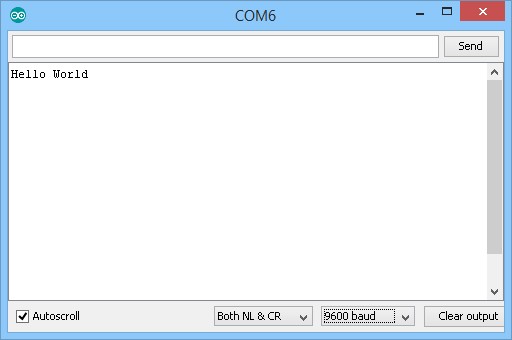
If you do not see the “Hello World” message you need to figure out what is wrong. If you managed to upload the sketch I think we can safely assume the Arduino is connected to the computer. This means it is likely you have the wrong baud rate selected.
Here I have a baud rate of 4800 and also 19200. You can see that I have garbage characters. This kind of output in the serial monitor is indicative of a baud rate mismatch.
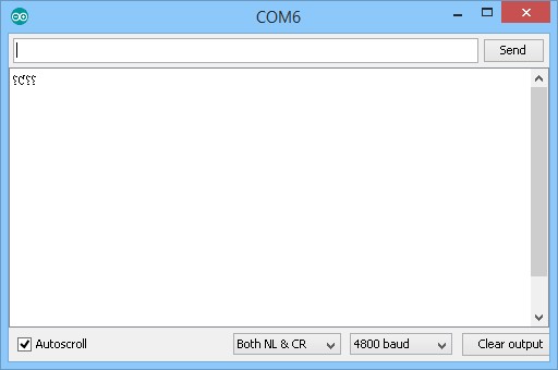


When using serial communications you need to make sure you are using the same baud rate at both ends. So how do you know what baud rate to use? It is the value you use when you begin the serial channel.
Serial.begin(9600); |
This tells the Arduino to open a serial channel at 9600 baud rate.It is actually telling the Arduino to open a hardware serial channel but we will get to that a little later. You then select the same value in the serial monitor.
![]()
Why 9600? No reason. There are many different rates I could have used. The important thing is to use the same speed at both sides.
End of Line Characters
If you print two strings you will see that they appear together on a single line.
// Basic serial print example. Serial_Example_002 void setup() { Serial.begin(9600); Serial.print("Hello World"); Serial.print("Another string"); } void loop() { } |
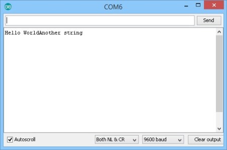
This is because we didn’t tell the serial monitor to start a new line after the “Hello World” message.
There are two line end characters; new line and carriage return. These are non visible, non printable characters that act as controls telling the serial monitor to go to the start of the next line. There are two ways we can add the end of line (EOL) characters
1 – add “\r\n” to what we are printing, or
2 – use Serial.println()
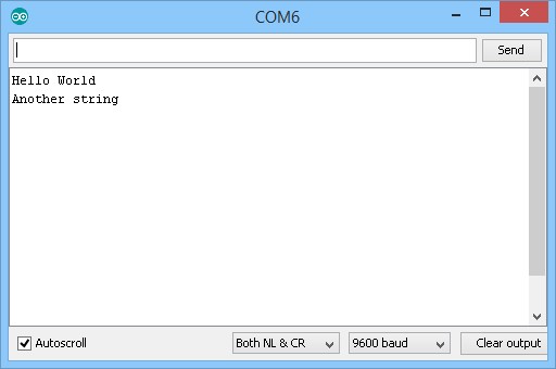
Both produce the same results and Serial.println() simply adds the “\r\n” characters to what it is printing.
// Basic serial print example. Serial_Example_003 void setup() { Serial.begin(9600); Serial.println("Hello World"); Serial.println("Another string"); } void loop() { } |
Using Serial.println() the EOL characters are added and the two messages are displayed on separate lines.
On a Windows system:
\r (Carriage Return). Moves the cursor to the beginning of the line without advancing to the next line
\n (Line Feed). Moves the cursor down a line without returning to the beginning of the line
\r\n (End Of Line): Combination of \r and \n
Serial monitor: Formatting output using the tab command
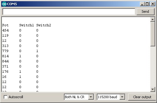
For quick and easy formatting spaces can be used but the output can become messy when the data has variable lengths. A better solution is the tab command “\t”. This works in exactly the same was as tab works in a word processor; it moves the cursor over to the next column and lines up the output.
For this example there are button switches connected to pin 14(A0) and 15(A1) and a potentiometer on pin A3
byte potPin = 17; byte switch1_pin = 14; byte switch2_pin = 15; int potVal = 0; boolean switch1State = 0; boolean switch2State = 0; void setup() { Serial.begin(115200); Serial.println(""); Serial.println("Pot\tSwitch1\tSwitch2"); } void loop() { potVal = analogRead(potPin); switch1State = digitalRead(switch1_pin); switch2State = digitalRead(switch2_pin); Serial.print(potVal); Serial.print("\t"); Serial.print(switch1State); Serial.print("\t"); Serial.println(switch2State); delay(500); } |
Using tab means the columns stay aligned regardless of how small or large potVal is (not totally true. If the value becomes too large the tab character will move the cursor over to the next tab column).
How fast is serial
Baud rate 9600bps mean 9600 bits per second. The Arduino uses the common 8N1 protocol which uses 10 bits for every character. This means (9600/10) 960 characters per second. This may seen fast but it is actually quite slow. 115200bps or 115200 bits per second is (115200/10) 11520 characters a second, much faster (but still slow by Arduino standards).
How fast can it go? Hardware serial on a 16 MHz Arduino is more than capable of 2,000,000 bps and with special considerations 2,500,000 bps is possible. As the speed gets higher you need to consider the clock speed and the transmission error percentage though. Software serial is very different and is much slower.
What is 8N1
8N1 is one of the more common serial protocols and means; 8 bits, no parity and 1 stop bit. It is slightly misleading as there are actually 10 bits, we also have a start bit. For more details start with the Sparkfun website or simply google it.
What is Transmission Error Percentage
Basically, it is the amount of error due to different frequencies being used by the host microprocessor and the baud rate. When the baud rate, does not match exactly the Arduino frequency there is a small % error that can cause timing drift.
![]()
If you look at the table above, you can see that, when using 9600 baud rate on a 16MHz Arduino, there is a 0.2% error rate. This means the baud rate is out of sync with the processors clock by 0.2%. Same for 38400 baud rate.
Different Arduino Serials
The Arduino has several implementations of serial UART. Not all are equal.
Hardware Serial/Serial
SoftwareSerial
AltSoftSerial
NeoSWSerial
Hardware Serial
Hardware serial, as the name may suggest, is built in to the Arduino hardware which means it has dedicated pins, the ones labelled RX and TX pins (pins 0 and 1). All Arduinos have at least one hardware serial channel.
Some, like the Mega, have more.
If the Arduino has a USB connector it is very likely the serial channel is connected to the USB via a a UART to USB adapter chip. All common Arduinos are like this and this is why you can print to the serial monitor when using usb.
Some Arduinos, or Arduino compatible boards, do not have the UART to USB chip. This means they cannot be directly connected to a PC and need an adapter.
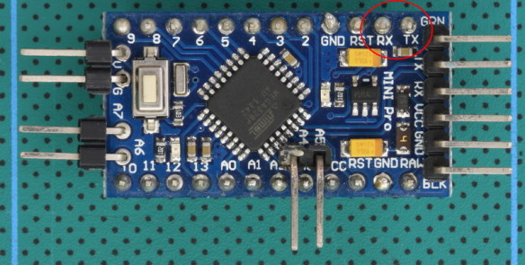
The Mini Pro has the serial pins but no USB connector.
Hardware serial has the best performance and is the most robust and reliable. This is always the best solution when available but it does have a caveat. The Arduino IDE uses the hardware serial to upload to the Arduino so when uploading new sketches you may need to disconnect what ever is connected to the RX and TX pins.
Hardware serial can:
– transmit and receive at the same time
– work while the Arduino is performing other tasks
– handle fast baud rates
Some Arduinos, such as the Mega and the Due, have more than 1 hardware serial. ATMega328 based Arduino have just one.
Hardware serial is integrated in to the IDE and adding a library is not required, all you need to do to initiate a serial connection is use the serial.begin() command.
void setup() { Serial.begin(115200); // 115200 is the serial port baud rate // remember to select the same baud rate in the serial monitor // wait for the serial port to connect. while (!Serial) { ; } Serial.println("Hello World"); } void loop() { } |
If this is new to you see the examples above.
Hardware Serial links
Arduino reference
The rest of the serial implementations are what they call software implementations. This means all the work is done in code which has benefits and drawbacks. If you want to try out any of the software based serials you will need a usb to serial adapter. See the examples below.
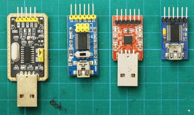
Various UART adapters.
SoftwareSerial
Software Serial is a library that is part of the standard Arduino IDE. To use it you need to add the library to the sketch and them tell it the pins you want to use. Here it is being initialised with pins 2 and 3. Pin 2 for recieve and pin 3 for transmit.
// Add the SoftwareSerial library #include <SoftwareSerial.h> // Initiate an instance of the SoftwareSerial class. Requires the pin numbers used for RX and TX. SoftwareSerial swSerial(2, 3); // RX, TX |
Since SoftwareSerial comes with the IDE and because it can use most of the Arduino pins it is a very convenient solution but does have drawbacks. It is not reliable at very slow or very fast speeds and because of how it works it can cause problems with timings.
SoftwareSerial uses pin-change interrupts when receiving data, and both receive and transmit use delay loops, and while it is delaying, interrupts are disabled. This means it blocks the sketch. The code simply sits and waits for SoftwareSerial to finish before it can do anything else.
Because interrupts are disabled, SoftwareSerial interferes with anything that uses interrupts.
SoftwareSerial:
– comes with the Arduino IDE as standard.
– can be used with almost all pins (see below)
– can not transmit and receive at the same time
– can have multiple instances but only one instance can be active at one time
– not very good at very slow or fast baud rates. The baud rate should be kept in the range 9600 – 38400
– requires a library which comes with the Arduino IDE by default
// Add the SoftwareSerial library #include <SoftwareSerial.h> // Initiate an instance of the SoftwareSerial class. Requires the pin numbers used for RX and TX. SoftwareSerial swSerial(2, 3); // RX, TX void setup() { // Start the connection and set the baud rate swSerial.begin(9600); swSerial.println("Hello, world!"); } void loop() { } |
Try using softwareSerial with different baud rates. What is the fastest you can get reliable communication? In my own experiments 38400 is the fastest I been able to get 100% error free communication and this was only when the Arduino wasn’t doing much else. After 38400 I start to see errors.
SoftwareSerial is convenient and is fairly flexible but it is not the best software serial choice.
AltSoftSerial
AltSoftSerial was written by Paul Stoffregen the creator of the Teensy range of boards. It is the best software serial implementation and should be used instead of the default SoftwareSerial where possible.
The AltSoftSerial library is available from the PJRC website or through the library manager. AltSoftSerial takes a different approach over the regular SoftwareSerial library. The pins it uses are fixed, pin 8 for receive, pin 9 for transmit (regular Arduinos only), and uses the 16 bit timer which means PWM on pin 10 becomes disabled.
AltSoftSerial:
– Can transmit and receive at the same time.
– Minimal interference when also using the Hardware Serial and other libraries
– More reliable at higher speeds than the other software serials
– Fixed pins: pin 8 for receive, pin 9 for transmit (regular Arduinos only*)
– Disables PWM on pin 10
– Uses the hardware Timer1 (16 bit) and will not work with other libraries that also need the same timer
*Check the PJRC website for the pins used other types of Arduinos.
// Add the AltSoftSerial library #include <AltSoftSerial.h> // Initiate an instance of the altSerial class // On ATmega 328 based Arduinos AltSoftSerial uses pin 8 for RX and pin 9 for TX AltSoftSerial altSerial; void setup() { altSerial.begin(9600); altSerial.println("Hello World"); } void loop() { } |
NeoSWSerial
NeoSWSerial was written by Slash Devin and it is the next best choice or at least better than the standard SoftwareSerial library. Like SoftwareSerial it can use most of the regular pins but has a limited range of baud rates, 9600 (default), 19200, 31250 (MIDI) and 38400 only. This isn’t really an issue though. The regular software serial has issues when used below 9600 and above 38400 so slower than 9600 and faster then 38400 shouldn’t be used.
NeoSWSerial:
– Can be used with most pins.
– Can receive and transmit at the same time.
– More friendly to interrupts on RX than SoftwareSerial
– Limited range of baud rates; 9600 (default), 19200, 31250 (MIDI) and 38400 only
Requires a library which can be downloaded from github or added through the library manager.
// Add the NeoSWSerial library #include <NeoSWSerial.h> // initiate an instance of the NeoSWSerial class. Requires the pin numbers used for RX and TX. // neoSerial( RX pin, TX pin ) NeoSWSerial neoSerial( 2, 3 ); void setup() { neoSerial.begin(9600); neoSerial.println("Hello World"); } void loop() { } |
So which one should I use?
Depends on what you are doing and how fast you want to do it. If you have to use a fast baud rate (such as 115200 or even 2,000,000) then the only option is the hardware serial. Software versions cannot handle these speeds.
If you do not need super fast rates and you have pins 8 and 9 available then AltSoftSerial is for you. Don’t have pins 8 or 9 and you are OK with one of the available baud rates then NeoSWSerial. If none of these work you are left with SoftwareSerial.
If you need more than one fast serial connection then you need an Arduino with more than one serial channel such as the Mega.
Using a software UART and usb adapter to talk to a PC
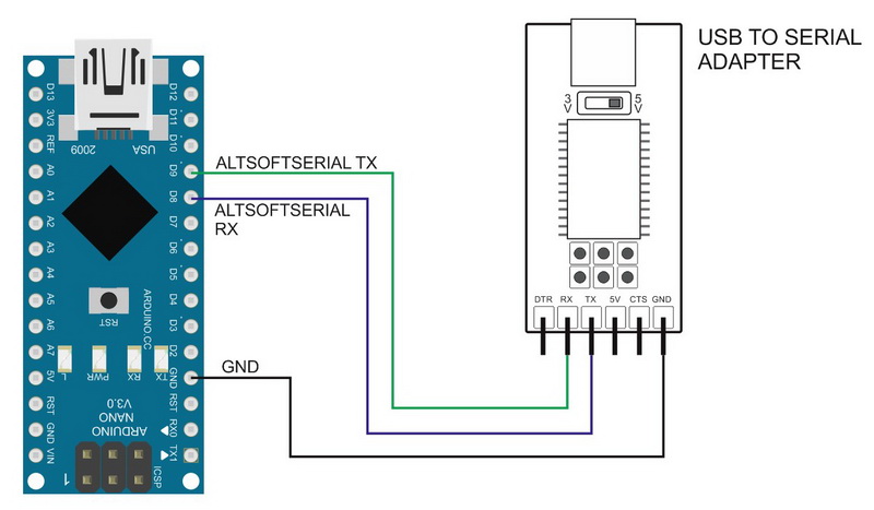
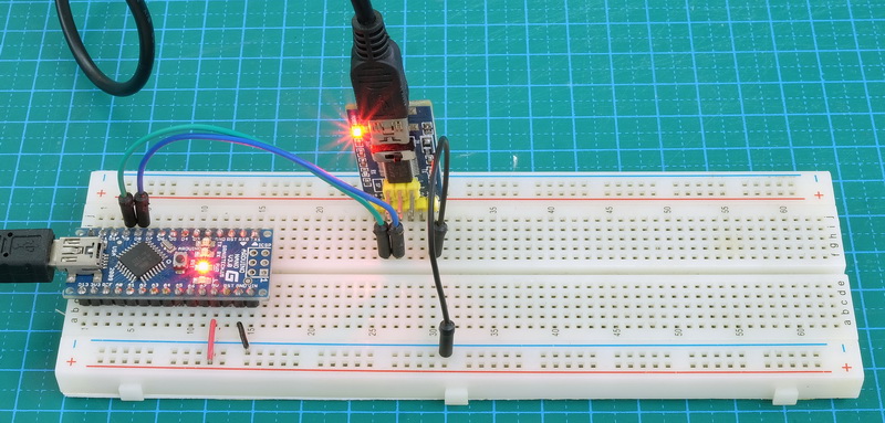
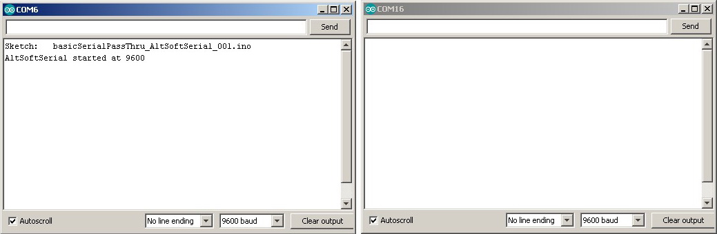
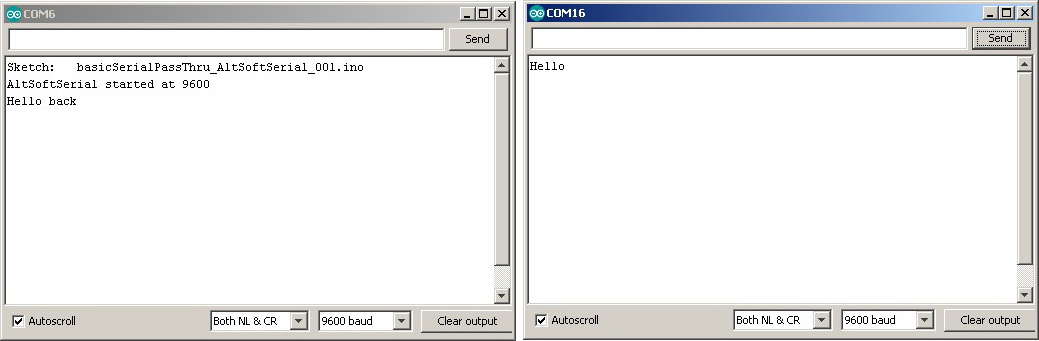
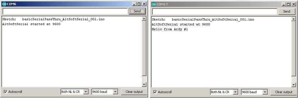
I think most people will have used the hardware serial to communicate with a connected PC using the serial monitor. If not see the examples above. Sometimes though it is useful to have another connection and we can do this using one of the software serials and a usb to serial adapter. Here I am using AltSoftSerial.
Simple circuit. The Arduino is connected to a PC using the standard USB connection and also by a usb to serial adapter. The usb to serial adapter is connected to pins 8 and 9 of the Arduino and AltSoftSerial is used to communicate over the usb to serial adapter. Power is delivered through usb. GNDs are connected.
Having two connections to the same PC gives you 2 COM ports; one for the Arduino and one for the adapter. In the example below the Arduino is on COM 6 and the usb adapter is on COM 16.
// basicSerialPassThru_AltSoftSerial_001 #include <AltSoftSerial.h> AltSoftSerial softSerial; char c=' '; void setup() { Serial.begin(9600); Serial.print("Sketch: "); Serial.println(__FILE__); softSerial.begin(9600); Serial.println("AltSoftSerial started at 9600"); } void loop() { // Read from the software serial and send to the hardware seral if (softSerial.available()) { c = softSerial.read(); Serial.write(c); } // Read from hardware serial and send to software serial if ( Serial.available() ) { c = Serial.read(); softSerial.write(c); } } |
Plug everything in, upload the sketch and try it out.
If you have the correct drivers installed for the usb to serial adapter you will have 2 COM ports; 1 for the Arduino, and 1 for the adapter. If you now open 2 serial monitors you can talk to yourself.
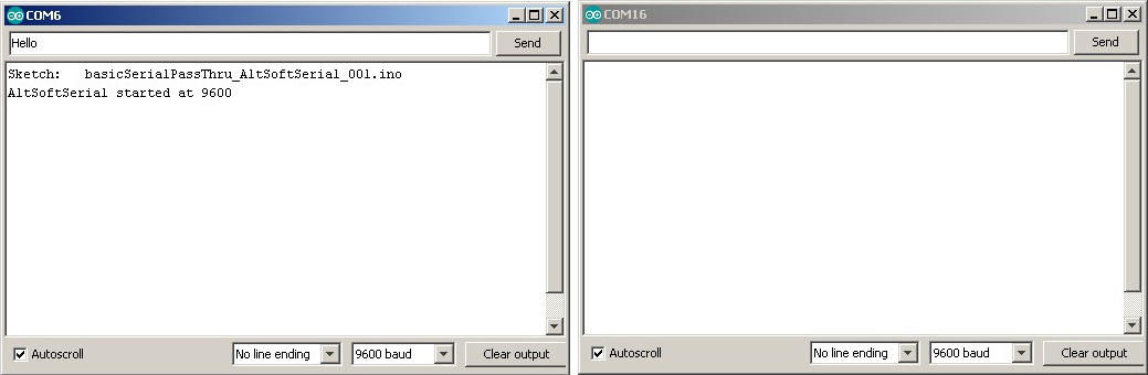
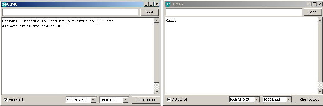
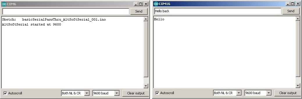
At first this may appear to be of no use but using the usb to serial adapter can be very useful for debugging when the hardware serial is used for other things. You should also be able to see that the usb to serial adapter can be replaced with any device that talks UART and there are many, including all the Bluetooth modules I have written about on the rest of this website. It also forms an easy way to get 2 Arduinos talking to each other. One example that I am currently working on is an IOT Wordclock. The Word clock uses an Arduino and an ESP8266. The Arduino does most of the work and the ESP8266 takes care of the wifi stuff like the control webpage and getting the time from a NIST server. The two talk to each other through a UART connection using software serial.
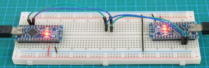
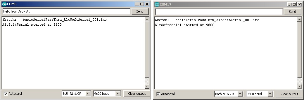
Here is an example of linking two Arduinos together using AltSoftSerial. Both Arduinos have the basicSerialPassThru_AltSoftSerial_001 sketch.
Remember that RX on one side goes to TX on the other side
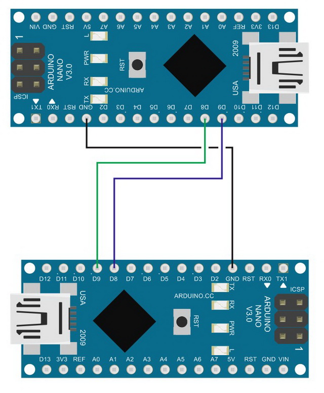
basicSerialPassThru_AltSoftSerial_001 sketch
// basicSerialPassThru_AltSoftSerial_001 #include <AltSoftSerial.h> AltSoftSerial softSerial; char c=' '; void setup() { Serial.begin(9600); Serial.print("Sketch: "); Serial.println(__FILE__); softSerial.begin(9600); Serial.println("AltSoftSerial started at 9600"); } void loop() { // Read from the software serial and send to the hardware serial if (softSerial.available()) { c = softSerial.read(); Serial.write(c); } // Read from hardware serial and send to software serial if ( Serial.available() ) { c = Serial.read(); softSerial.write(c); } } |
I have used this sketch (or a version of it) many times throughout the website. It is the sketch I use when I am experimenting with Bluetooth modules (or anything that uses UART).
The sketch is very simple. It first initialises the hardware serial and soft serial and then prints a welcome message to the serial monitor (using the hardware serial channel).
void setup() { Serial.begin(9600); Serial.print("Sketch: "); Serial.println(__FILE__); softSerial.begin(9600); Serial.println("AltSoftSerial started at 9600"); } |
Of course, before we can initiate AltSoftSerial we need to tell the compiler to load the library
#include <AltSoftSerial.h> AltSoftSerial softSerial; |
Inside the main loop we check to see if there are any characters available on the software serial channel and if there are we read the first one and write it to the hardware serial channel. This prints it in the serial monitor.
// Read from the software serial and send to the hardware serial if (softSerial.available()) { c = softSerial.read(); Serial.write(c); } |
It then checks the hardware serial. If data is available it reads the first character and sends it to the software serial channel. You should notice that nothing is sent to the serial monitor. You could, if you wish, echo what ever is entered in the serial monitor back to itself.
void loop() { // Read from hardware serial and send to software serial if ( Serial.available() ) { c = Serial.read(); softSerial.write(c); } |
Although only one character is read at a time because the main loop is constantly looping we eventually get all available characters.
Buffer Size
Most Arduinos, that is Arduinos with 1023 bytes or more of RAM, have a 64 character buffer for serial input and output. For most uses this is fine but care needs to be taken when a lot of data is being transmitted.
When the input buffer is full any new data received is discarded, it simply disappears. This can lead to issues with data disappearing, sometimes in the unexpected ways.
Imagine you are receiving 200 bytes of data. The Arduino receives the first 64 bytes and the buffer gets full. The data is still arriving but bytes 65 onwards are lost. If the buffer is not emptied bytes 65 to 200 are lost.
Now imaging that you start to read the data at around the point that byte 100 is received. Bytes 65 to 99 are still lost but the buffer now has space so bytes 100 onwards are stored. This means to have a chunk of data in the middle of the sequence missing (bytes 65 to 100).
The only way around this is to keep emptying the buffer and ensure you always have space for new data (or change the buffer size but that is advanced tinkering).
Sending data is different; when data is transmitted if the output buffer is full the print/write function blocks until there is space for the remaining data.
Serial Commands
If you look at the Arduino reference for serial you will see that serial has the following commands available:
begin()
end()
If (Serial)
print()
println()
write()
availableForWrite()
read()
readBytes()
readBytesUntil()
available()
setTimeout()
find()
findUntil()
parseFloat()
parseInt()
peek()
flush()
serialEvent()
It is very possible to produce very complex serial sketches and not use the majority of the serial commands. I have used about 5 of the above commands only. Commands like find() and findUntil(), I prefer to create my own routines that perform similar functions but without blindly deleting data (more below). Having said that I do feel it is useful to have an understanding of the commands and how they work.
begin(baudRate)
You have already seen above, begin() is used to start or enable serial. Serial doesn’t work unless you initiate it. The program will compile OK but nothing will be sent out over serial. Remember to use the same baud rate at both ends.
Serial.begin(9600); |
end()
end() closes or disables serial. For hardware serial this is not normally required but can be used if you ever need to use the RX and TX pins for other things after using serial. The serial RX and TX pins, Pins D0 and D1, can be used as regular pins when not using serial. I can’t think of a reason why you would want to do this though. If you need to use pins 0 and 1 then you are highly unlikely to use them for serial communication.
end() can be useful when using software serial. You can implement more than one software serial but can use only one channel at a time. This means you need to open and close channels as you want to use them.
Serial.end(); |
If (Serial)
Checks to see if serial communication is available but take care, on most Arduinos Serial always returns TRUE even if you have not initiated the serial channel.
This command is only useful when used for the Leonardo (which has a usb CDC connection) and works as you may expect; TRUE when serial is available and FALSE when it is not. It does not work with Serial1 on the Leonardo which always returns TRUE. In the examples above you may have noticed
// wait for the serial port to connect. while (!Serial) { ; } |
This is just for the Leonardo and waits for serial to be available before continuing..
print(), println() and write()
I have already mentioned the difference between print() and println(). println() adds carriage return and new line characters (\r\n) and print() does not. But what does print() and println() actually do and how are they different to write()?
According to the Arduino reference
Serial.write() writes binary data to the serial port.
Serial.print() prints data to the serial port as human-readable ASCII text.
This sounds fairly straight forward but there is more to it that that and isn’t all data binary anyway.
print() and write() may at first seem to be the same but there are some key differences. print() and println() convert all numeric values to human-readable ASCII text. write() doesn’t convert anything. It simply sends what you give it. This makes write() more efficient and faster than print/println().
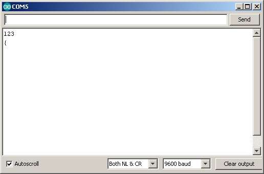
What is the difference between binary and human-readable ASCII text? It is the difference between the value 1 and the character that represents a 1. IE ASCII 48 which is “1”.
Serial.print(123); displays “123” in the serial monitor (3 characters). The value 123 is converted to the ASCII characters “1” + “2” + “3”. Serial.write(123) sends a single byte with the value of 123. (123 is the ascii code for the “{” character so Serial.write(123) displays a “{” in the serial monitor). This seems straight forward but Serial.write() can handle strings. Serial.write(“123”) sends the ASCII characters “1” + “2” + “3”, this is because you are giving a string to the write command not a value. Sometimes it is easy to mix up string representations of numbers and actual values. “1” and 1 are not the same.
// Serial_Example_003_print_v_write void setup() { Serial.begin(9600); Serial.println(123); Serial.write(123); } void loop() { } |
If you are not familiar with the ASCII table it is worth looking up. A good place to start is www.asciitable.com.
As you can see there is some overlap between Serial.print() and Serial.write. For example; Serial.print(“HELLO”) and Serial.write(“HELLO”) results in the same thing, “HELLO”. There are differences though, they handle numbers differently, print() can handle more data types, and has a built in base convertor.
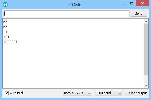
Serial.print() can be used to display values in different base formats. For example as Hexadecimal or binary.
void setup() { Serial.begin(9600); // wait for the serial port to connect. Required for Leonardo native USB port only while (!Serial) { ; } int value = 65; Serial.println(value); // print as an ASCII-encoded decimal Serial.println(value, DEC); // print as an ASCII-encoded decimal Serial.println(value, HEX); // print as an ASCII-encoded hexadecimal Serial.println(value, OCT); // print as an ASCII-encoded octal Serial.println(value, BIN); // print as an ASCII-encoded binary } void loop() { } |
What happens if you use Serial.write(value);? I will leave this to you to find out.
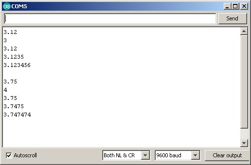
Serial.print() can be used to display floating point numbers. As with other values the number is converted to ascii, so the value 3.1234 becomes “3.1234”. When printing floats the default number of decimal places is 2. This means
float f = 3.1234; Serial.print(f) |
results in 3.12 being displayed.
As seen above print() has a optional second parameter. We used it above to change the base format. When printing floats the second parameter can be used to specify the number of decimal places.
When truncating a floating point value, print() will round up the value.
// Serial_Example_006_print_floats void setup() { Serial.begin(9600); // wait for the serial port to connect. Required for Leonardo native USB port only while (!Serial) { ; } float f; f = 3.123456; Serial.println(f); Serial.println(f,0); Serial.println(f,2); Serial.println(f,4); Serial.println(f,6); //print a blank line Serial.println(""); f = 3.747474; Serial.println(f); Serial.println(f,0); Serial.println(f,2); Serial.println(f,4); Serial.println(f,6); } void loop() { } |
Unfortunately you cannot send a floating point value using write();
Serial.write(f); |
If you try the compiler gives you a “call of overloaded ‘write(float&)’ is ambiguous” error. This basically means the write() function can’t handle floats. There are ways to send actual values and I will try to cover them later.
availableForWrite()
returns the number of bytes (an int) in the serial output buffer. It is basically the number of characters left to write.
int numChars = Serial.availableForWrite(); |
Most people probably do not need to worry to much about this but it can be useful in situations where you must be sure all serial data has been sent before doing the next function. Remember, when using the hardware serial, serial data is sent in the background so as soon as the serial.print() command has copied the data to the output buffer your code moves on. This means the next instructions in your code are being executed while data is still being sent. See also Serial.flush().
read()
reads a single character or byte from the serial input buffer. Data received over serial is stored in the buffer until the sketch reads them. If the buffer is empty read() returns -1
You can see an example of this is the serial pass through sketch above.
// Read from hardware serial and send to software serial if ( Serial.available() ) { c = Serial.read(); softSerial.write(c); } |
if ( Serial.available() ) – Check to see if data is available. Serial.available() returns the number of bytes in the buffer. Any value > 0 is classed as not FALSE. I am using it here as a check to make sure we have at least 1 character of serial data before trying to read it.
readBytes(buffer, length)
similar to read() except you can specify how many bytes to read. It is like having read() inside a for loop.
readBytes() expects 2 parameters; the buffer (variable) where to copy the data to and the number of bytes to read.
buffer is a char or byte array (char[] or byte[])
length is an int.
readBytes() returns the number of bytes copied. If nothing was copied it returns 0.
int length = 10; char buffer [11]; int numberOfBytes = Serial.readBytes(buffer, length) // if numberOfBytes >0 we have data. // if numberOfBytes =10 we have all the data. |
As with all c arrays, make sure the array or buffer is large enough to hold the data you are copying to it. The compiler won’t tell you if you make a mistake the sketch will simply start acting strange.
readBytesUntil(termChar,buffer,length)
like readBytes() but you can now specify a terminator character/byte. The terminating character is not copied to the buffer.
For example, if you have data that always ends with a byte valued 13 you can use readBytesUntil():
termChar is a char or byte
buffer is a char or byte array (char[ ] or byte[ ])
length is an int.
int length = 10; char buffer [11]; char termChar = 13; int numberOfBytes = Serial.readBytesUntil(termChar,buffer, length) // if numberOfBytes >0 we have data. |
This is a handy command if you do not always have the same length data. The command simply reads the data until it finds the terminating character. You have to make sure the receiving buffer is large enough to accommodate the data though.
The default timeout for readBytes() and readBytesUntil() is 1 second (1000ms). This can be changed with setTimeout().
I personally do not like to use readBytes() or readBytesUntil(). They wait until all the bytes are available (or until they timeout) and while waiting they block the sketch. A better way, at least to me, is to create your own loop and use read() to copy the data. This allows you to check availability of data and only copy if data is there. If no data is available you can go and do other things. See examples of “Blink Without Delay” for examples of this technique.
setTimeout()
change the timeout time used in readBytes() and readBytesUntil(). The time specified is in milliseconds.
The value is a long ctype data value.
Set the timeout to half a second (500ms).
Serial.setTimeout(500); |
find(searchString)
Serial.find() checks the serial input buffer for a given string (char array). Returns TRUE if the string is found and FALSE if it is not found (times out). There are a couple of things to be aware off:
1 – it deletes data from the buffer as it searches.
2 – it blocks the sketch while it is doing its thing.
find() reads the serial input buffer, removing characters as it goes, until it finds the search string or it fully empties the buffer and times out. If you have a search string “abc” and the buffer contains “1234567890”, find() will empty the buffer, timeout, and then return FALSE.
If the buffer contains “hello world” and you search for “world”, find() runs through the buffer, deleting characters as it goes, until it finds “world”. find() then returns “TRUE”. In the process of searching for “world” the function removes the string from the serial buffer. This means, if the buffer contains “hello world” and you search for “world”, the function will return TRUE but the serial buffer will be empty. Any data in the buffer after “world” will remain.
find() blocks all other operations on the Arduino while it is working and has to sit and wait until find() is finished before moving to the next operation.
void setup() { Serial.begin(9600); // allow time for the serial data to arrive delay(4000); // serial buffer contains "hello world" char searchString[] = "world"; boolean found = Serial.find(searchString); if(found) { Serial.println("The world has been found"); } else { Serial.println("The world has been lost"); } } void loop() { } |
I personally feel find() is not that useful and it is far better to copy the serial data to a buffer and then search the buffer. In almost all my projects I control what data is sent and received so the chances are if data exists it is needed for something so using a command like find() that deletes data is not useful to me. This may just be me though. I suppose if you are receiving data that you have no control over and you are only interested in specific values then find() could be used, still better to copy the data to your own buffer and then search this buffer though.
findUntil(searchString, terminatingString)
Similar to find() except findUntil() adds a terminator string. The function searches the serial input buffer looking for the search string until either:
1 – the search string is found
2 – the terminator string is found
3 – nothing is found and it times out.
If the search string is found the function returns TRUE, if not found, it returns FALSE.
If the terminator string is found the function stops looking and returns FALSE.
char searchString[] = "zzz"; char termString[] = "\n"; void setup() { Serial.begin(9600); boolean found = Serial.findUntil(searchString, termString); Serial.print("searchString "); if(found) { Serial.println("found"); } else { Serial.println("not found"); } } void loop() { } |
A minor thing to consider. It is worth remembering that the Arduino sends the EOL charatcers in “\r” “\n” order. If the serial buffer contains “abcd/r/n”. The above will return FALSE and empty the buffer. If you use “\n” as the terminating string, the function will still return FALSE but will leave the “/r” character in the buffer. That remaining character can screw things up when you don’t know it is there.
parseInt()
parseInt() returns the first valid ascii formatted (long) integer number found in the serial buffer. Characters that are not integers (or the minus sign) are skipped.
parseInt() runs through the serial buffer looking for characters that could be part of an integer. When looking it will delete any non numeric character until it finds an integer. If it does not find a valid value it will empty the buffer, time out and return 0. If an integer is found any characters/data after the integer are left in the serial buffer. If the buffer only contains a valid integer, parseInt() will read the available data and then wait for the timeout before returning the value. This can cause performance issues.
If the buffer contains “12345” then parseInt() returns 12345 and the buffer will be empty.
If the buffer contains “abd1234zxy”. parseInt() returns 1234 and the buffer will contain “xyx”. The “abc” will be deleted.
If the buffer contains “-3434\r\n”. parseInt() returns -3434 and the buffer will have “\r\n” after the function has finished.
It is worth highlighting that parseInt() returns a long, which in Arduino land is a 4 byte value. parseInt() will work if you use an Arduino int (which is a 2 byte value) as long as the value is < 32,767 but you will run in to problems if the value is > 32,767 because when the long is copied to the int it will lose 2 bytes and so the value will change. For example; the signed long value 2147483640 gets truncated to -8 when converted to a signed int.
long parseIntValue = Serial.parseInt(); |
Always copy the return value into a long variable.
parseFloat()
Serial.parseFloat() returns the first valid ascii formated floating point number from the serial buffer. The function returns empty handed (0) if a floating point number is not found or the timeout is reached. The data does not need to be in the buffer at the time the function is called but the function will block your code while it waits for data to arrive.
parsefloat runs through the serial buffer deleting non floating point characters (non-numbers and non-minus sign) until it finds a number or minus sign. It then reads the floating point data until it reaches another non float character. It then converts the ascii formatted value in to an actual floating point value.
If the serial buffer contains “abc3.1234abcdefg”. parseFloat() will delete the first “abc”, find the 3.1234 and leave “abcdefg” in the serial buffer.
Serial.peek()
Serial.peek() returns the next character in the serial buffer without removing it. It is like read() except it does not delete anything. Very useful if you want to create your own parser and need to see what the next character is without disturbing it.
peek() can only be used to read the first available character. Unlike read() it does not increment the buffer pointer or change the buffer so successive peeks() will return the same character.
Serial.flush()
This is a command many people get wrong, including myself when I first started with the Arduino. It is easy to assume you know what it does from the name especially if you have experience with other programming languages.
The Arduino reference contains the sentence “Waits for the transmission of outgoing serial data to complete. (Prior to Arduino 1.0, this instead removed any buffered incoming serial data.).” Besides knowing that the function changed with IDE 1.0 the important bit is “Waits for the transmission of outgoing serial data to complete.”. What does this mean? It means Serial.flush() does not instantly clear the buffer(s) but makes the Arduino wait until all the current serial data is sent.
Hardware serial works in the background, this is why you can use it while doing other things. When you use Serial.print(“HELLO WORLD”); the Arduino copies the “HELLO WORLD” data to the output buffer and then returns to your main code. It then uses interrupts to actually send the data in the background while still processing your sketch. This is normally a good thing, but, sometimes it can be a problem and you may want to wait until all the data has been sent before continuing with your program. This is where Serial.flush() can be used just keep in mind that the delay can be quite long.
serialEvent()
serialEvent() is not really a Serial command. It is a function that is called once every loop when there is data in the serial input buffer. (The function is actually called outside of the loop() function but that is not important here). It is like having a if(Serial.available) outside of the main loop() function.
// Serial_Example_012_serialEvent char c = ' '; char buffer [21]; int pos = 0; bool stringComplete = false; void setup() { Serial.begin(9600); Serial.println("START"); } void loop() { if (stringComplete) { Serial.println(buffer); buffer[0] = '\0'; stringComplete = false; pos=0; } } void serialEvent() { char c = (char)Serial.read(); buffer[pos] = c; pos++; if (c == 10) { stringComplete = true; } } |
You should notice that there is no call to serialEvent() inside the sketch.The call is done outside of the the call to loop().
The above works and is fairly robust but I have never used it in any of my projects. Using
void loop() { if (Serial.available()) { char c = Serial.read(); // do something with c } } |
is far simpler and has exactly the same effect.
The following produces exactly the same output as the one above but uses if (Serial.available()) and is easier to read and maintain.
// Serial_Example_012b_serialEvent char c = ' '; char buffer [21]; int pos = 0; bool stringComplete = false; void setup() { Serial.begin(9600); Serial.println("START"); } void loop() { if(Serial.available()) { char c = (char)Serial.read(); buffer[pos] = c; pos++; if (c == 10) { stringComplete = true; } } if (stringComplete) { Serial.println(buffer); buffer[0] = '\0'; stringComplete = false; pos=0; } } |
In part 2 I look at serial data and data formats.
Martyn, thanks so much for the post.Really thank you! Keep writing.
Very useful article! You explained many doubts to me. Thank you.
Well done Marty.
Wonderful explanations. Suddenly, everything becomes clear :-)
Keep posting please!
Will Arduino Serial Part 2 be completed?
It is already completed.
Arduino Serial: A Look at the Different Serial Libraries
Very well done tutorial. Thank you Martyn for sharing your knowledge. You have great pedagogical talents.
Jacques Bourdouxhe
Great document, thanks.
Thankyou …. I can now run in the light with the Arduino instead of walking in the dark .. unfortunately you don’t know me and you will never know how much you have helped someone who struggles to program Thankyou a (1000); times
You can change the serial buffer size. It is a #define in the code. You can modify the source file directly or your ide may allow you to override the #define at the project level.
For the board I’m using currently it is SERIAL_RX_BUFFER_SIZE, located in
C:\Program Files (x86)\Arduino\hardware\arduino\avr\cores\arduino\HardwareSerial.h
For a Teensy using Serial1 it is SERIAL1_RX_BUFFER_SIZE located in
C:\Program Files (x86)\Arduino\hardware\teensy\avr\cores\teensy3\serial1.c
steve
Very informative and easy to understand example of how to reference the serial function. I have took so much time reading and searching various other references – and its all in this single page. Totally unaware that sofwareSerial is limited to low bauds such as 38000, so presents the options to use the other, more reliable options.
So, as a novice, is it possible to use the hardwareSerial for connected devices such as BT, GSM modules and include softwareSerial (via an FTDI on respective pins) for serial debugging?
yes, and this is how I generally do things.
But, because the usb to serial also uses the hardware serial pins you may need to remove the hardware serial connections when uploading new code.
Great article , can you write article on how to connect mega2560 and nodemcu via serial , i have initiated Software Serial on NodeMCU on pin D2(RX) , D3(T3) and have connected it to mega D18(TX1) , D19(RX1) , also i have connected Ground of arduino to NodeMCU G pin but i have no success with it am getting invalid characters on terminal of mega side , although both serial baud rate is same 9600 , so am not sure what is wrong , few days ago i was able to communicate ok but now i cant not sure how i have done it few days ago as i have disconnected circuit i made few days ago.
You say: “Try using softwareSerial with different baud rates. What is the fastest you can get reliable communication? In my own experiments 38400 is the fastest I been able to get 100% error free communication and this was only when the Arduino wasn’t doing much else. After 38400 I start to see errors.”
I have had been working with HC-05 and softwareSerial with a rate of 115200. Too many problems!!
I chose 38400 and works fine!!
Thanks Martyn, your info is very helpfull!!
Javier