Update 19.09.2015
The FC-114 boards I have have the Bolutek firmware. User DS has reported that he/she has FC-114 boards that have the linvorV1.8 firmware. So if the below does not work for you then check what firmware you have.
I may be missing something but I can not get the HC-05 FC-114 boards in to Master Mode and connect to other BT devices with just AT commands. The modules say they have accepted the commands, such as AT+ROLE1 but when I try to connect to other modules I get the error message “Can only be used in Lord Mode”.
The modules accept “AT+ROLE1” and report they have changed mode but they haven’t really.
In an earlier post I mentioned that it looks likes pin 27 or pin 28 has to be pulled HIGH to enter Master Mode and this does indeed seem to be the case. Everything I have tried without pulling the pin(s) HIGH has failed.
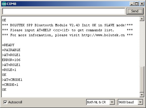
They reply with “OK” and if you interrogate with “AT+ROLE” they report “+ROLE=1” but they are actually still in Slave Mode.
The user guide shows the pin outs:
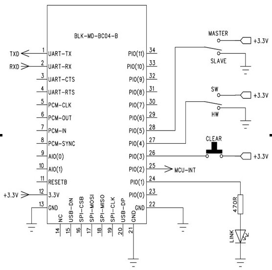
There are 2 options for entering Master Mode; bring Pin 27 HIGH or bring pin 28 HIGH. Pin 27 allows you to use software and pin 28 allows you to use a hardware switch.
When pin 27 is HIGH you use AT commands to enter Master Mode. When pin 28 is HIGH (and pin 27 LOW or NC) the modules automatically switch to Master Mode. To me both ways are about the same and I decided to go with pin 27.
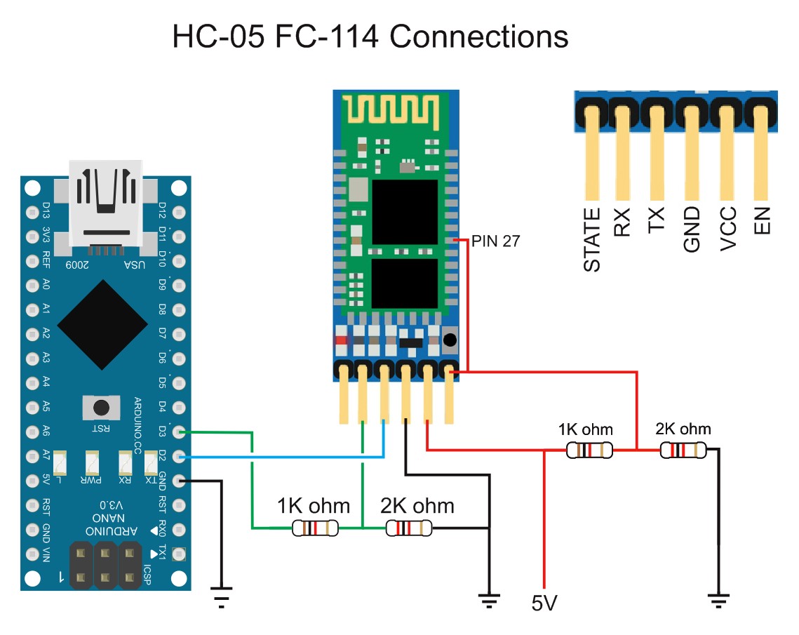
So, to get pin 27 HIGH I soldered a wire between pin 27 and the EN pin on the breakout boards. I used wire wrap wire which is fine single core and ideal for this kind of thing.
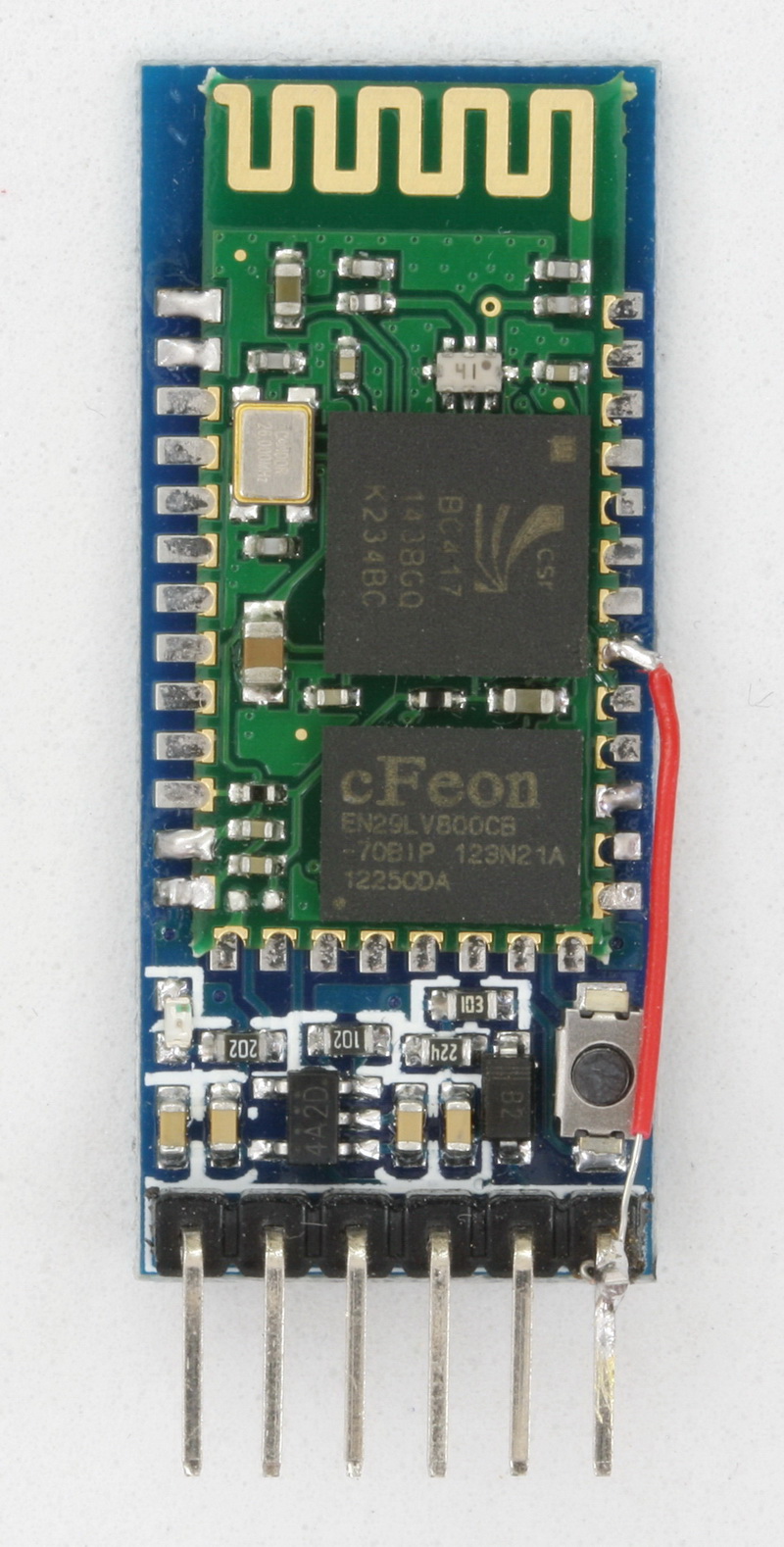
Not the finest example of soldering but good enough.
I realized after I soldered the wire that I didn’t know if the EN pin was actually used on the FC-114 modules. However, pulling EN HIGH does get me in to AT Mode and does not seem to affect the modules in any other way.
Update 22.08.2015
The EN pin when brought LOW disables the module, same as the zs-040 modules. Since I am unlikely to use the EN pin to disable the module I am leaving the wire as it is. You may not want to connect it.
Remember that the pins on the mini BT board are 3.3v only. So to pull pin 27 HIGH you need to use 3.3v not 5V.
Here is the bread board set up.
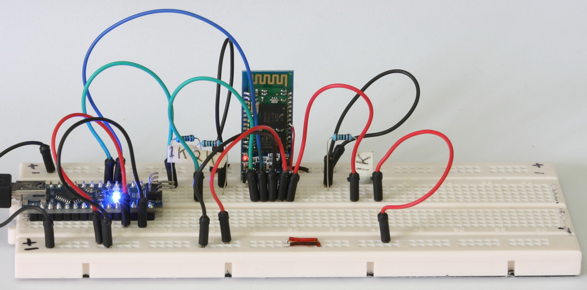
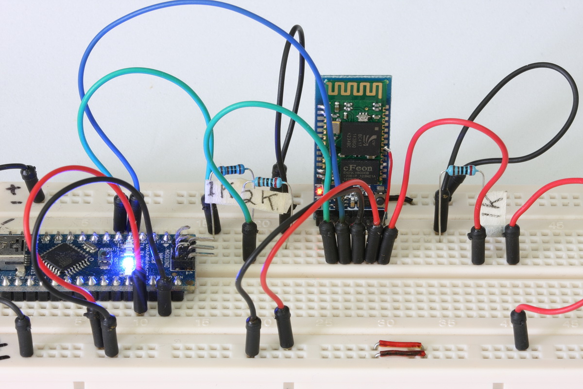
The EN pin is connected to a voltage divider (a 1k ohm resistor and a 2K ohm resistor) and then to 5V. The voltage divider reduces the 5V to 3.3v.
Connections
– Arduino D2 to BT TX
– Arduino D3 to voltage divider and then to BT RX
– Arduino 5v out to BT vcc in
– HC-05 pin 27 to voltage divider then to Vcc
– GND to GND
Make the connections and upload the following sketch to the HC-05 FC-114.
Arduin0 Sketch HC-0x_FC-114_01_9600
// Basic bluetooth test sketch. HC-0x_FC-114_01_9600 // Uses hardware serial to talk to the host computer and software serial for communication with the bluetooth module // // Pins // BT VCC to Arduino 5V out. // BT GND to GND // Arduino D3 to BT RX through a voltage divider // Arduino D2 BT TX (no need voltage divider) // // When a command is entered in the serial monitor on the computer // the Arduino will relay it to the bluetooth module and display the result. // // The HC-0x FC-114 modules require CR and NL #include <SoftwareSerial.h> SoftwareSerial BTSerial(2, 3); // RX | TX char c=' '; boolean NL = true; void setup() { Serial.begin(9600); Serial.println("Sketch HC-0x_FC-114_01_9600"); Serial.println("Arduino with HC-0x FC-114 is ready"); Serial.println("Make sure Both NL & CR are set"); Serial.println(""); // FC-114 default baud rate is 9600 BTSerial.begin(9600); Serial.println("BTserial started at 9600"); Serial.println(""); } void loop() { // Read from the Bluetooth module and send to the Arduino Serial Monitor if (BTSerial.available()) { c = BTSerial.read(); Serial.write(c); } // Read from the Serial Monitor and send to the Bluetooth module if (Serial.available()) { c = Serial.read(); BTSerial.write(c); // Echo the user input to the main window. The ">" character indicates the user entered text. if (NL) { Serial.print(">"); NL = false; } Serial.write(c); if (c==10) { NL = true; } } } |
Set up a Slave Device – HC-06
I have a HC-06 on a separate bread board. I’m not doing anything with this except powering it and allowing the HC-05 to connect to it.
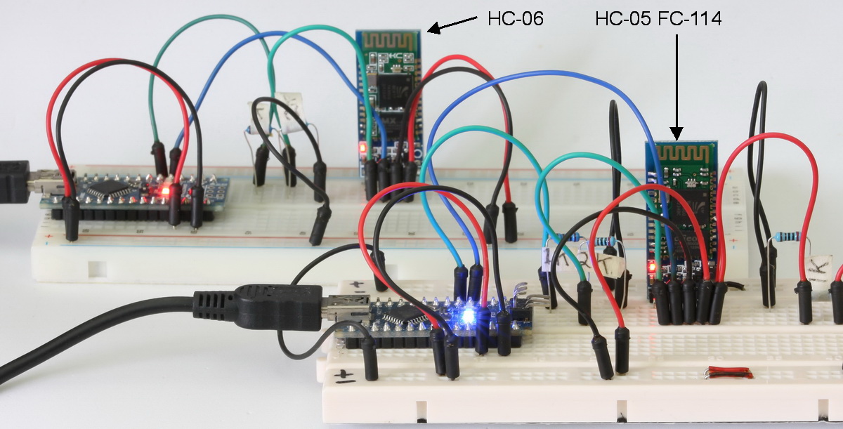
Set up Auto Connect on the HC-05 FC-114
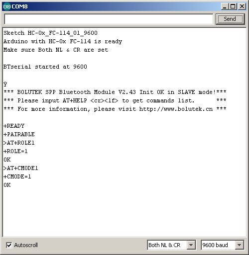
Open the serial monitor and cycle the power to the HC-05 FC-114. The LED on the HC-05 should be blinking; 1 second on, 1 second off.
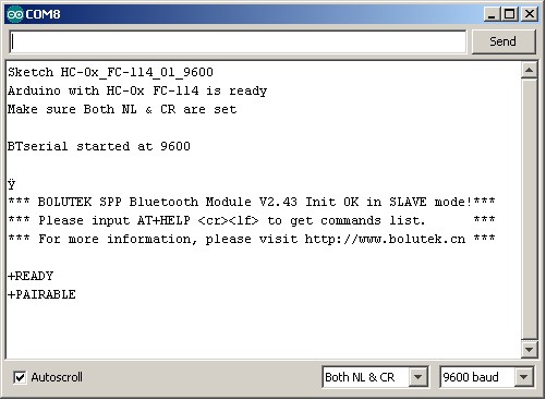
Make sure “Both NL & CR” are selected and enter the following:
AT+ROLE1
AT+CMODE1
AT+ROLE1 puts the module in to Master Mode.
AT+CMODE1 allows the module to connect to any other BT slave device.
The LED should still have the same blink pattern; 1 second on, 1 second off.
The LED on the HC-06 should be blinking about 5 times a second.
With the serial monitor open cycle the power to the HC-05. The welcome message should now say “MASTER mode”.
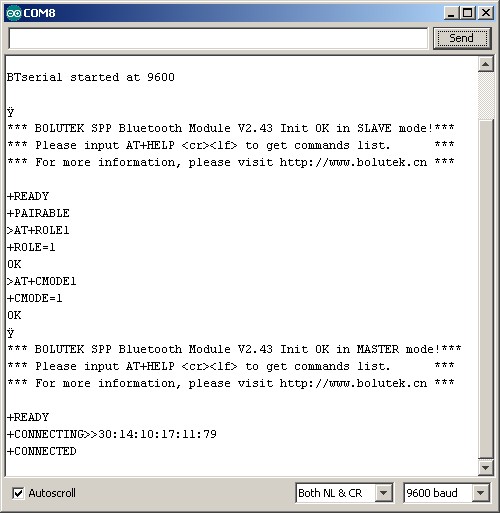
When you re-power the HC-05 it will search for connectible Bluetooth devices and then auto connect to the strongest signal. While it is searching the LED will blink quickly 3 times every couple of seconds. Connection should take no more than a couple of seconds.
Once connected, the LED on the HC-05 is constant on.
One of the nice things about the HC-05 Fc-114 modules is that they output the current status and you can monitor when they are connecting and then connected.
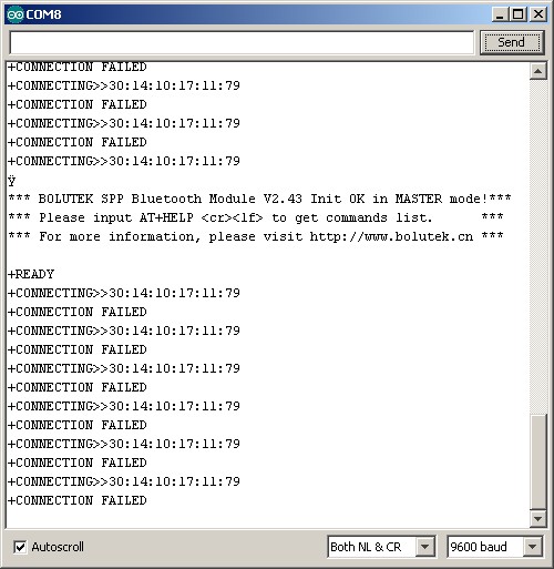
The module seems to remember the first slave device it connects to and will try to connect to the same module when the power is cycled. I have set up 2 more HC-06s and these seem to be ignored, even when the original HC-06 is not powered.
Once the module has been set up you no longer need to have pin 27 HIGH. The HC-05 Fc-114s will auto connect even without power to pin 27.
Update:
I have now been playing with this for a couple of hours, constantly stopping and starting the HC-05. It always connects to the original HC-06 even when other HC-06s and HC-05s (in slave mode) are available.
Thx for the tutorial.
I have another version of HC-05 FC-114. This one say VERSION:2.0-20100601 and comes with other AT-commands.
Hi,
When i put pin 27 in HIGH it put my module in AT command as would do pin 34 and my module doesn’t seem to get to master mode. Any connection is made with my other module
Hi Thanks for sharing ! I really need your help.
I have a question. I’m wondering if you used two computers for the connection
between HC-06 and HC-05. I mean, Did you monitor the two Arduino serial monitors
on just one computer?
One computer, 2 serial monitors. I have IDE version 1.0.5 installed and I also use the portable version of 1.6.3.
I believe you can run 2 instances of the same IDE and so open 2 serial monitors using the same IDE
Thank you for your answer! I have one more question. I thought you posted just hc05 master module cording but it was hc 0x. Do i have to use this cording in 05 and 06 modules each other?? Do i have to change “x” into “5” or “6” as well??
The sketch works with HC-05 and HC-06. The x replaces the 5 and 6.
Hi, Sir. ! you can help me a question? I own two HC-05. I have a code adapted to create USBs gamepads for AVR microcontrollers. When I connect the AVR into a USB port and place one of the Bluetooth modules as “Slave”, this device receives signals from any Android device through Bluetooth communication. I can control games on PC, with my Samsung Galxy, for example.
I am trying to adapt a design of a SNES controller to Android, via Bluetooth and Arduino, to make the SNES controller can send signals via bluetooth to my “AVR USB gamepad”.
But I have doubts on the question of pairing. The modules connect only if one is in Master mode and the other in Slave Mode.
In the example of the SNES Arduino control for Android, the module must be in Slave mode. If the module is in Master mode, no Android is able to recognize it.
My question is :
I can make two HC-05 modules connect both being as “Slave”?
Because I think the module as “Slave”, the module is “Transceiver”.
If I can not connect both modules as Slave, how I do to the slave module receives the signals I’m sending module that is as master ? the code that I did , isn’t working. You could guide me on what to do ?
Thank you in advance.
If you want to connect 2 HC-05s together then one of them must be a master and one must be a slave.
As you have found out, when using an Android device it is regarded as the master device and the HC-05 must be the slave.
My solution would be to have the HC-05 connected to the AVR as the slave. Then set to HC-05 connected to the game pad as a master. You can then connect an Android device or the game pad to the AVR.
Thanks, Sir. In my country, your knowledge on the subject is like a “bible”. I will follow all your instructions and try to achieve the goal. Greetings !
Sir Martyn, just one more question and I promise that I do not bother you anymore. Is there any other Bluetooth module that can be connected to an Arduino and enabling connection with an HC-05 module, both as “transceivers Slaves” ? Thank you in advance.
The HC-05 can be either a master or slave. You set which one through the AT commands.
The Arduino can control the HC-05 and can change the HC-05 settings automatically. You just need to have a way of putting the HC-05 in to AT mode. Remember though, different modules have different ways of doing this.
Once the HC-05 is in AT mode you can use the Arduino to issue AT commands.
Have a look at Entering AT Mode Method 2. Using the Arduino to Control the HC-05 which is part of the https://www.martyncurrey.com/arduino-with-hc-05-bluetooth-module-at-mode/ post.
Please note that the method to get in to AT mode may not be the same for your module. For example if you have the FC114 version you will need to add a wire to pin 27 or pin 28, see above.
Dear Marty,
I have some problem calling AT+INQ when in AT Mode. Did I done anything wrong here?
The command and replies entered:
>AT
OK
>AT+CMODE=1
OK
>AT+ROLE
+ROLE:1
OK
>AT+INQM
+INQM:1,9,48
>AT+INQ
ERROR:(16)
I tried using “AT+INIT” the HC05 will just blink rapidly and no “AT” commands could work, unless pulling the EN wire to low while pressing the button on HC 05.
The model I am using is FC 114 and running on version 2.0-20100601.
Advanced thanks for your help and advise. :)
Audrey
2.0-20100601 is the firmware version I have on some zs-040 boards. See https://www.martyncurrey.com/arduino-with-hc-05-bluetooth-module-at-mode/ for general AT mode guide. For connecting 2 modules see https://www.martyncurrey.com/connecting-2-arduinos-by-bluetooth-using-a-hc-05-and-a-hc-06-easy-method-using-cmode/ and https://www.martyncurrey.com/connecting-2-arduinos-by-bluetooth-using-a-hc-05-and-a-hc-06-pair-bind-and-link/
I have this exact same problem , with the same module and firmware 2.0-20100601
The ERROR(16) means : SPP lib hasn’t been initialized. but if I tried AT+INIT, the led starts flashing fast and no commands are accepted anymore, for any command I write, I get no response from the module :(
Any solution ?
Thank you
Hello Martyn, I can build up with 2 modules HC6 a connection BT and how this goes.
HC-06 modules are slave only and cannot connect together.
You need a master and a slave to form a connection. This means at least one HC-05.
hello Martyn,
i have two module HC-05(zs-040) and HC-06(fc-114), can i make both modules auto connect ?
please reply !!
yes it is possible.
If you have the older zs-040 board see https://www.martyncurrey.com/connecting-2-arduinos-by-bluetooth-using-a-hc-05-and-a-hc-06-pair-bind-and-link/.
Note. There are newer zs040 modules that have a blue LED on the daughter board. There have a different firmware. I have not tried these yet.
ok, modules worked
thank you very much sir
now, if modules is connected, i will turn on pin 13 !!
how to do it ??
see https://www.martyncurrey.com/arduino-to-arduino-by-bluetooth/
Hi Martyn,
I found this website very useful for learning about bluetooth modules. I have a problem with HC06 which is similar to the model above; it can send strange character. I have tried serveral sketches in arduino but no avail including yours:
// Basic bluetooth test sketch. HC-0x_FC-114_01_9600
// Uses hardware serial to talk to the host computer and software serial for communication with the bluetooth module
//
// Pins
// BT VCC to Arduino 5V out.
// BT GND to GND
// Arduino D3 to BT RX through a voltage divider
// Arduino D2 BT TX (no need voltage divider)
//
// When a command is entered in the serial monitor on the computer
// the Arduino will relay it to the bluetooth module and display the result.
//
// The HC-0x FC-114 modules require CR and NL
#include
SoftwareSerial BTSerial(0, 1); // RX | TX // I change this based on my wiring
char c = ‘ ‘;
boolean NL = true;
void setup()
{
Serial.begin(9600);
Serial.println(“Sketch HC-0x_FC-114_01_9600”);
Serial.println(“Arduino with HC-0x FC-114 is ready”);
Serial.println(“Make sure Both NL & CR are set”);
Serial.println(“”);
// FC-114 default baud rate is 9600
BTSerial.begin(38400);
Serial.println(“BTserial started at 9600”);
Serial.println(“”);
}
void loop()
{
// Read from the Bluetooth module and send to the Arduino Serial Monitor
if (BTSerial.available())
{
c = BTSerial.read();
Serial.println(“====”);
Serial.write(c);
}
// Read from the Serial Monitor and send to the Bluetooth module
if (Serial.available())
{
c = Serial.read();
BTSerial.write(c);
// Echo the user input to the main window. The “>” character indicates the user entered text.
if (NL) { Serial.print(“>”); NL = false; }
Serial.write(c);
if (c==10) { NL = true; }
}
}
/// end of line
it prints strange characters such as
h>þ
hþ
hÿ
hÿ
hÿ
I have change the baud rates, no luck. what’s wrong with my module? is it broken? wrong library?
Thanks for any help
Hi, I did it by changing the baud rate 115200. it’s kinda strange but it works like a charm. Now, I still struggle to get it in at mode.
Hello Mr. Currey
Even though I am not using an Arduino board, I wonder if you can help me.
I am using an HC-05 connected to a FRDM-K64F computer. The slave is an android tablet running Bluetooth Chat. I created a routine that sets up the HC-05 as a MASTER as follows:
AT+RMAAD
AT+ROLE=1
AT+RESET
AT+INIT
AT+PAIR=C8A8,23,355D9E,60
AT+BIND=C8A8,23,355D9E
AT+CMODE=1
AT+LINK=C8A8,23,355D9E
and then I enter a loop where I can read and write.
This works fine but only for the 60 seconds specified in the PAIR command and then it disconnects. I don’t mind that.
What I want is a routine that will automatically connect without having to pair again. I tried many ways including the following:
AT+ROLE=1
AT+RESET
AT+INIT
AT+BIND=C8A8,23,355D9E
AT+LINK=C8A8,23,355D9E
I get the connect but can not transfer data. The LED on the HC-05 does not blink as it does during the 60 seconds of the PAIR command.
Can you tell me what I am doing wrong or where I can find an answer.
Thanks
Eli Naiman
HC-05s remember the last 7 devices they have been paired with so once you have paired you do not need to do it again so it does not need to be part of the routine. Do it manually and forget about it.
Making connections with Bluetooth Classic is a two stage process; pairing and then connecting. Pairing allows the two devices to talk, it does not actually form the connection.
You don’t say which HC-05 you have so it’s hard to know for sure but I initially suspect the Android device is acting as the master not the HC-05 but I may be wrong.
If not already, try going through the process manually. This will require some kind of serial in / serial out routine. Like the one above but for you board. A USB UART adaptor and a PC with a terminal app can be used as well.
Although basically the same, have a look at https://www.martyncurrey.com/connecting-2-arduinos-by-bluetooth-using-a-hc-05-and-a-hc-06-pair-bind-and-link/ which goes through the process for a slightly different Bluetooth module.
Hello, i have firmwave HC-05 version 2.0-20161226. Name modul H-C-2010-06-01. Comand AT+INQ error 1F? What is the problem? Help. I enter the following commands.
AT+RMAAD
AT+ROLE=1
AT+RESET
AT+CMODE=0
AT+INQM=0,5,9
AT+INIT (error 17)
AT+INQ (error 1F)
Slave module N2 (HC-05 slave) – OK, i`m see from may android phone.
did according to your lesson
https://www.martyncurrey.com/connecting-2-arduinos-by-bluetooth-using-a-hc-05-and-a-hc-06-pair-bind-and-link/
I can’t think of anything of the top of my head. When I get time I will try to look in to it.
Was wondering if I could get some help. I’m trying to connect a HC-06 to a serial port on a Meade Lx-200gps telescope. I’m not sure if I should run as a slave or master and how to change it. Any ideas? again its a hc-06 and dsd tech said I need to change it so you must be able to. Thx so much. David Klein [email removed]
As far as I can see the telescope has a standard UART interface so a HC-06 should connect as usual:
GND – GND (remember to connect the GNDs)
RX – TX
TX – RX
I am not certain but it looks like the telescope has a CAT5 socket so you may need an adapter.
Once connected you should be able to pair with a master device and then talk to the telescope.
The HC-06 is a slave only device which means it can only accept a connection request it cannot make one so you would need a master device such as an android phone to make the connection.
You may already be aware that the HC-06 is Bluetooth Classic only and as such will not work with Apple devices. For Apple you need BLE.
I am not familiar with the Meade Lx-200gps but there is quite a bit on line and googling “Meade Lx-200gps telescope bluetooth” should give you plenty to read.
Hi sir, can you help me i configure already the master and slave mode they have the same blinking pattern but when i tried to connect an android device. I can’t find the master nor the slave in my bluetooth connection. thanks !!