In a previous post I showed how the HC-05 can auto connect to other Bluetooth devices by setting the HC-05 to pair with any device using CMODE=1. This is quick and easy but does not give any control over which other device the HC-05 connects to.
In this post I show how to set up the HC-05 to always connect to the same HC-06 (or HC-05 in Slave mode). For this we use PAIR, BIND, and LINK.
NOTE: There are now newer modules that use a 3.0-20170601 firmware. This guide does not work for these modules (AT+INQ gives an error). I do not have any of the new modules and cannot find a reliable supplier. I have ordered 3 sets of BT modules believing they were the newer ones only to receive old ones.
If you have not yet bought BT Classic modules. I recommend buying the original HC ones. These are slightly (just a little bit) more expensive but are well supported and full documentation is available. Original HC modules have the HC logo screen printed on the main BT board and the current boards have a blue LED top left.
I am using 2 separate Arduino IDEs; version 1.6.3 which is installed, and version 1.0.5 which I run from a folder (it is the non install version). This allows me to use 2 IDEs at the same time, each connected to a different Arduino. It also gives me 2 serial monitors, one for each Arduino.
The modules used are the zs-040 versions of the HC-05 and the HC-06. The HC-05 has the Wavesen/HC firmware 2.0-20100601 and any any module running the same firmware will be the same.
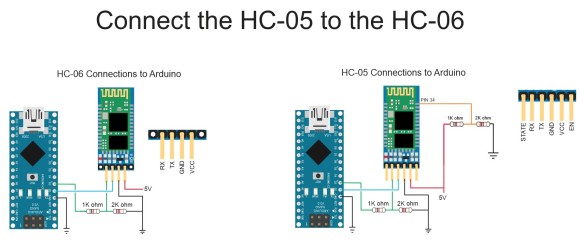
The HC-05 has 2 AT command modes which I refer to as “mini” AT mode and “full” AT mode and some commands only work when in “full” AT mode. To enter “full” AT mode pin 34 needs to be HIGH and kept HIGH. To accomplish this I have made a connection from pin 34 to +3.3v. See the diagram below (or after the jump).
If you are not sure about At command mode take a look at Arduino with HC-05 (ZS-040) Bluetooth module – AT MODE
If you are not familiar with how the HC-06 and HC-05 work it may be worth while checking out some of the other posts:
HC-05 and HC-06 zs-040 Bluetooth modules
Arduino and HC-06 (ZS-040)
Arduino With HC-05 Bluetooth Module in Slave Mode
Connecting 2 Arduinos by Bluetooth using a HC-05 and a HC-06: Easy Method Using CMODE
Connections
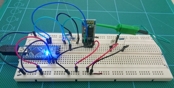
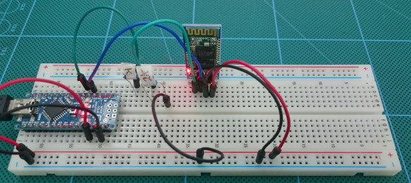
I have 2 Arduinos. One connected to a HC-05 zs-040 and one connected to a HC-06 zs-040.
The HC-05 has a connection from pin 34 to +3.3v. This activates “full” AT mode.
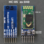
HC-05 Set Up
I have the HC-05 set with the following values:
– ROLE = 0 (slave mode)
– UART = 9600 (baud rate for communication mode)
– CMODE = 0 (only connect to paired devices)
– PSWD = 1234 (password/PIN for pairing)
In AT mode I will be using a baud rate of 38400.
Build the circuit, power on and load the following sketch.
// Basic Bluetooth sketch HC-05_02_38400 // Connect the HC-05 module and communicate using the serial monitor // // The HC-05 defaults to commincation mode when first powered on. // Needs to be placed in to AT mode // After a factory reset the default baud rate for communication mode is 38400 // // // Pins // BT VCC to Arduino 5V out. // BT GND to GND // BT RX to Arduino pin 3 (through a voltage divider) // BT TX to Arduino pin 2 (no need voltage divider) #include <SoftwareSerial.h> SoftwareSerial BTserial(2, 3); // RX | TX // Connect the HC-05 TX to Arduino pin 2 RX. // Connect the HC-05 RX to Arduino pin 3 TX through a voltage divider. char c = ' '; void setup() { // start th serial communication with the host computer Serial.begin(9600); Serial.println("Arduino with HC-05 is ready"); // start communication with the HC-05 using 38400 BTserial.begin(38400); Serial.println("BTserial started at 38400"); } void loop() { // Keep reading from HC-05 and send to Arduino Serial Monitor if (BTserial.available()) { c = BTserial.read(); Serial.write(c); } // Keep reading from Arduino Serial Monitor and send to HC-05 if (Serial.available()) { c = Serial.read(); // mirror the commands back to the serial monitor // makes it easy to follow the commands Serial.write(c); BTserial.write(c); } } |
Because pin 34 on the Bluetooth module is brought HIGH, the HC-05 should enter AT mode on power on.
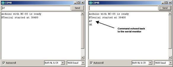
Open the serial monitor on the host computer and confirm you are in AT mode by typing “AT” (no quotes). You should get a reply of “OK”
Remember that the HC-05 requires “Both NL & CR” to be set.
The sketch echos the commands you enter back to the serial monitor. This makes it a bit easier to follow.
HC-06 Set Up
Build the HC-06 circuit, power on and load the following sketch. My HC-06 is set to use 9600 baud rate. If yours is using a different speed then you will need to change the sketch. Change the following lines:
BTSerial.begin(9600);
Serial.println(“BTserial started at 9600”);
Change the 9600 to what ever speed your HC-06 is using.
// Basic bluetooth test sketch. HC-06_01_9600 // HC-06 ZS-040 // // // Uses hardware serial to talk to the host computer and software serial for communication with the bluetooth module // // Pins // BT VCC to Arduino 5V out. // BT GND to GND // BT RX to Arduino pin 3 (through a voltage divider) // BT TX to Arduino pin 2 (no need voltage divider) // // When a command is entered in the serial monitor on the computer // the Arduino will relay it to the bluetooth module and display the result. // // These HC-06 modules require capital letters and no line ending // #include <SoftwareSerial.h> SoftwareSerial BTSerial(2, 3); // RX | TX void setup() { Serial.begin(9600); Serial.println("Arduino with HC-06 is ready"); // HC-06 default baud rate is 9600 BTSerial.begin(9600); Serial.println("BTserial started at 9600"); } void loop() { // Keep reading from HC-06 and send to Arduino Serial Monitor if (BTSerial.available()) Serial.write(BTSerial.read()); // Keep reading from Arduino Serial Monitor and send to HC-06 if (Serial.available()) BTSerial.write(Serial.read()); } |
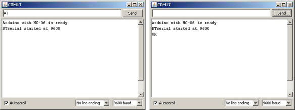
HC-06 modules start in AT mode so we can start entering commands as soon as we open the serial monitor. Remember that the HC-06 requires commands to be upper case and does not want new lines or carriage returns so set “No line endings” at the bottom of the serial monitor window. Open the serial monitor on the host computer and confirm you are in AT mode by typing “AT” (no quotes). You should get a reply of “OK”
We don’t need to do much to prepare the HC-06. Just make sure the password is the same as the HC-05.
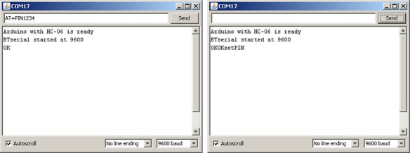
To change the password/PIN to 1234 enter “AT+PSWD1234” (no quotes) and click Send
Pairing and Binding
At this point we should have the HC-06 waiting for a connection. The password/PIN is 1234.
The HC-05 should be in “full” AT mode. If you are not sure what this is see Arduino with HC-05 (ZS-040) Bluetooth module – AT MODE
The steps to connect to the HC-06 are
1. set the same baud rate on both devices.
2. make sure the passwords on the HC-05 and the HC-06 are the same
3. find the address of the HC-06
4. pair the HC-05 with the HC-06
5. bind the HC-06 to the HC-05
6. set the HC-05 to only connect with paired devices
7. link to the HC-06
1. Set the same baud rate on both devices.
Set the communication mode baud rate to 9600 on the HC-05 and the HC-06. I have already done this.
This is only for the purpose of this example. Once you have got everything working you can change the baud rates.
2. Make sure the passwords on the HC-05 and the HC-06 are the same
We have already set the passwords.
3. Find the address of the HC-06
You can do this with an Android device or you can do it with the HC-05. Here is how to it with the HC-05.
Make sure the HC-05 is in AT mode and enter the following commands.
AT+RMAAD
AT+ROLE=1
AT+RESET
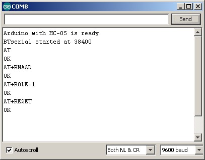
AT+RMAAD clears any previously paired devices.
AT+ROLE=1 puts the HC-05 in Master Mode
AT+RESET reset the HC-05. This is sometimes needed after changing roles.
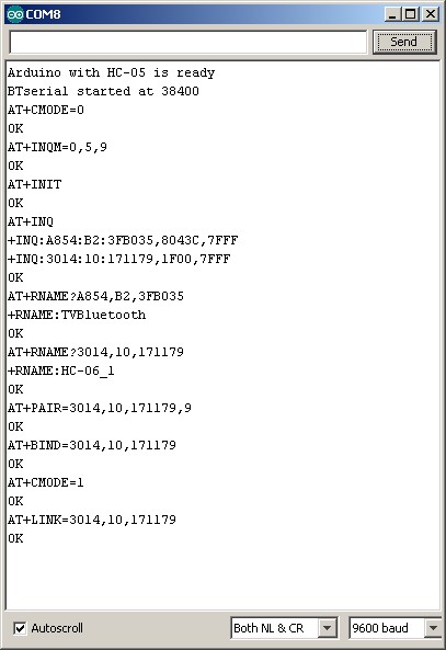
Now enter the following
AT+CMODE=0
AT+INQM=0,5,9
AT+INIT
AT+INQ
AT+INQM=0,5,9, AT+INIT and AT+INQ require pin 34 to be HIGH. If pin 34 is not HIGH then you will not receive any reply from these commands. No message, no error message.
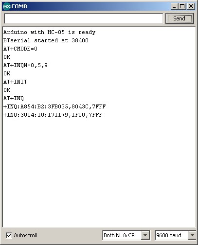
AT+CMODE=0 allows the HC-05 to connect to any device
AT+INQM=0,5,9 set inquiry to search for up to 5 devices for 9 seconds
AT+INIT initiates the SPP profile. If SPP is already active you will get an error(17) which you can ignore.
AT+INQ searches for other Bluetooth devices.
In the above screen shot you can see that the HC-05 found 2 Bluetooth devices.
+INQ:A854:B2:3FB035,8043C,7FFF
+INQ:3014:10:171179,1F00,7FFF
One of these is the HC-06. To find out we can use the AT+RNAME? command.
AT+INQ returns 3 values, the first is the address and this is the value we need. The second value is the class of the device and the third value is the signal strength (RSSI).
AT+INQ will only work if the HC-05 is in Master Mode and after a AT+INIT command.
To get the name of the found devices we use the AT+RNAME?
When we enter the address we need to replace the colons with commas. The format is AT+RNAME?A854,B2,3FB035 and AT+RNAME?3014,10,171179
Of course, you would use the address of your HC-06.
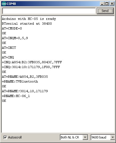
You can see from the above. A854:B2:3FB035 is my TV and 3014:10:171179 is the HC-06.
Now we have the address of the HC-06 we can finish making the connection.
4. Pair the HC-05 with the HC-06
To pair we use the AT+PAIR=<addr>,<timeout> command.
Enter “AT+PAIR=3014,10,171179,9” (no quotes)
If the HC-05 cannot pair with the HC-06 within 9 seconds you will get an error message. If the pairing is successful you will get an “OK”
5. Bind the HC-06 to the HC-05
Bind using “AT+BIND=3014,10,171179”
6. Set the HC-05 to only connect with paired devices
We do this with the CMODE command – “AT+CMODE=1”
7. Link to the HC-06
Use the link command AT+LINK=<addr>
In my case “AT+LINK=3014,10,171179”. If all is well you will get the “OK” reply.
The LED on the HC-05 should have 2 quick blinks every 2 seconds (or so).
The LED on the HC-06 should be on (not blinking).
You have now connected the HC-05 and the HC-06
Now that the connection has been formed, the HC-05 will automatically connect to the HC-06 every time they are turned on.
Once the connection is formed the HC-05 will switch to communication mode. If you want to continue with AT Mode then you will need to reset the module with pin 34 HIGH or with the button switch closed.
Test The Connection
On the HC-05, remove the connection to pin 34 and upload the following sketch to the Arduino connected to it. The sketch opens the BTserial at 9600 for communication mode.
// Basic Bluetooth sketch HC-05_03_9600 // Connect the HC-05 module and communicate using the serial monitor // // The HC-05 defaults to commincation mode when first powered on. // Needs to be placed in to AT mode // After a factory reset the default baud rate for communication mode is 38400 // // // Pins // BT VCC to Arduino 5V out. // BT GND to GND // BT RX to Arduino pin 3 (through a voltage divider) // BT TX to Arduino pin 2 (no need voltage divider) #include <SoftwareSerial.h> SoftwareSerial BTserial(2, 3); // RX | TX // Connect the HC-05 TX to Arduino pin 2 RX. // Connect the HC-05 RX to Arduino pin 3 TX through a voltage divider. char c = ' '; void setup() { // start the serial communication with the host computer Serial.begin(9600); Serial.println("Arduino with HC-05 is ready"); // start communication with the HC-05 using 9600 BTserial.begin(9600); Serial.println("BTserial started at 9600"); } void loop() { // Keep reading from HC-05 and send to Arduino Serial Monitor if (BTserial.available()) { c = BTserial.read(); Serial.write(c); } // Keep reading from Arduino Serial Monitor and send to HC-05 if (Serial.available()) { c = Serial.read(); BTserial.write(c); } } |
Reset both Arduinos and remove power from the HC-05 and the HC-06
Power on the HC-06. The LED should be rapidly blinking 5 times per second. This indicates it is waiting for a connection or to be paired.
Power on the HC-05. The LED will blink a couple of times when first on and then change to a the regular pattern of blinking quickly every couple of seconds.
The LED on the HC-06 will turn on full time (no blinking).
The modules are now connected.
Open the serial monitors and what ever you enter in one will appear the the other and visa versa
Every time the modules are powered on they should connect. If you find they do not connect then cycle the power to the Arduinos. Sometimes the HC-05 will get stuck trying to make a connection. In this case the LED on the HC-05 will either
1. quickly blink 3 times every couple of seconds.
2. blink on/off twice a second.
This normally happens when the HC-06 is turned off and then back on again without resetting the HC-05.
The devices seem to connect more quickly when the HC-06 is started first.
Additional information
For more information about AT commands look at the HC-05 user guide or the EGBT-046S/EGBT-045MS user guide
Phillipe Cantin has a similar article here
Next step. Get Arduinos talking over Bluetooth. Arduino to Arduino by Bluetooth
Reference: https://www.martyncurrey.com/connecting-2-arduinos-by-bluetooth-using-a-hc-05-and-a-hc-06-pair-bind-and-link/
Hello Martyn,
Great BT posts. Thanks for your efforts which have made it simple and clear what and how to work these fun and handy modules – HC-05, HC-06 & ZS-040.
In your more recent post about pairing the HC-05 & HC-06 there are some typos. I’ve shown below. I may have missed others. I also have some suggestions for the article to help the readers, me ;-).
I have some editing suggestions below:
Clarifications
Top of the document after first Arduino code reference/listing you write,
“The LED on the HC-05… 5 times a second… device is in slave mode.” Rather than Slave Mode – This is actually indicating that the device is ready and waiting to be connected/paired. Not the mode?
Typos
Section 7. Link to the slave device
-> “The LED on the HC-06 should have two quick…” (should be HC-05).
-> “Now that the connection… HC-05… to the HC-05 every time…” (should be HC-06).
Reference:
It would be good to again reference techbitar as base for your AT command code. And if you used his other code for your other code also. I know you referenced him in another blog but, each blog stands alone so it is helpful to have references/statements throughout or begin having a bibliography and footnotes.
Great layouts on your blogs. I find them easy reads.
Additions
* You mention to put the device into AT mode and do not describe how this is done. It would be helpful to add a link to the ‘How to’ of yours.
* Ref. note to the ZS-040 to hold down the button to gain ‘full’ AT Mode and link to your description of the modes.
* Method 2 for query of the device address. You give a great tutorial on how to gain a remote devices MAC address from the HC-05. It would be helpful in this blog describing how to setup two (2) BT devices how to simply query the HC-06 device for its address then type it into the HC-05. I did see this in another blog of yours.
Hint/Tip
At you connection description where you describe “the HC-06 no blink and HC-05… quickly every couple of seconds…” Add a note that when pairing with another HC-05 or the ZS-040 the two connected device’s LEDs will each quickly blink and pause in unison.
Side Note:
If you haven’t yet experimented – The Arduino IDE will run multiple instances of the same version on Windows. You can have the same version of the IDE with multiple instances by simply double clicking on the app icon for several mcu boards. I’ve been running the IDE this way for a few years. I commonly play with a couple boards at a time.
Forgive me for my edit/suggestion note not being as complete and clear as your blog.
Thanks again! Good stuff you have put on the net.
Best Regards,
Brian Stott
Springfield, MO
Hi Brian, thanks for the kind words.
I have started to add clarifications and to make the corrections. Some points I want to double check when I get time.
I didn’t have a lot of time when I was doing this and obviously didn’t proof read it. I also changed the setup after I started the write up and missed some of the bits that should have been changed.
While updating I did think about other things I have not tried or have not included. I will try to make further updates at the weekend. This is a regular pattern for me. As I think of new things I will go back end add to old posts.
you said that: “the LED on the HC-05 should have two quick blinks every 2seconds (or so)
the LED on the HC-06 should be on (NOT BLINKING)
you have now connected the HC 05 and the HC 06”
when i paired my master and slave module (both HC -05), they BOTH blink quickly twice every 2seconds.
what does this mean?
thank you :)
Not sure what the 2 blinks on the HC-06 means. On the HC-05 it normally means there is an active connection.
When doing the above; pairing, binding and linking here are the LED patterns I get.
Before pairing
HC-05 – blinks quickly about 5 times per second
HC-06 – blinks quickly about 5 times per second
After pairing
HC-05 – blinks quickly about 5 times per second
HC-06 – blinks quickly about 5 times per second
After binding
HC-05 – blinks quickly about 5 times per second
HC-06 – blinks quickly about 5 times per second
After CMODE
HC-05 – blinks quickly about 5 times per second
HC-06 – blinks quickly about 5 times per second
After linking
HC-05 – blinks quickly 2 times every 2 or 3 seconds
HC-06 – LED is on (no blinking)
hi martyn,
we’re having trouble pairing the modules. i connected the HC 05 (MASTER) to arduino NANO and the another HC 05 (SET AS SLAVE) to arduino MEGA.
can you write a sketch for the SLAVE module using arduino MEGA?
thank you :)
See the sketch at the bottom of https://www.martyncurrey.com/using-an-arduino-mega-with-a-hc-05-zs-040-at-mode/
This assumes the BT module is connected to serial1 at 9600.
hi Martyn,
sorry for always bothering you but i need some help
we already paired the 2 bluetooth modules and we tried to test the communication between the modules using the sketch below. The slave module is connected to a 16×2 LCD display.
everytime we run the sketch, the slave status is “inactive”
how could we make this active?
thank you :)
#include
#include
#define rxPin 18
#define txPin 19
#define lcd1 30
#define lcd2 31
#define lcd3 32
#define lcd4 33
#define lcd5 34
#define lcd6 35
SoftwareSerial master(rxPin,txPin);
LiquidCrystal lcd(7,8,9,10,11,12);
void setup() {
Serial.begin(9600);
lcd.begin(16,2);
master.begin(9600);
}
void loop() {
master.listen();
if(master.isListening()){
lcd.setCursor(0,0);
lcd.print(“Slave BT Status”);
lcd.setCursor(0,1);
lcd.print(“ACTIVE”);
}
else{
lcd.setCursor(0,0);
lcd.print(“Slave BT Status”);
lcd.setCursor(0,1);
lcd.print(“INACTIVE”);
}
}
Break the problem down in to smaller tasks.
1. get the BT modules talking using the serial monitor
2. get the LCD working
3. combine 1 and 2.
If not already a member, join the Arduino forum. http://forum.arduino.cc/index.php
The forum is a better place to for dealing with code and there are many very helpful people on there.
After you join the Arduino forum let me know your user name.
hi Martyn,
I post the same question in arduino forum in this site
https://forum.arduino.cc/index.php?topic=339637.0
my username is Ram05
Sorry I posted the wrong link.
here’s the link to my post
http://forum.arduino.cc/index.php?topic=340521.0
thank you
Hi,
I have left a message on the Arduino Forum.
Hi thanks for this nice post……. i could not connect my fc-114 HC-05 to my pc or android it shows “paired but not connected” could u please help me in this regard…..
The FC-114 modules use a different firmware. I have some basic guides at:
https://www.martyncurrey.com/hc-05-fc-114-and-hc-06-fc-114-first-look/
https://www.martyncurrey.com/hc-05-fc-114-and-hc-06-fc-114-part-2-basic-at-commands/
https://www.martyncurrey.com/hc-05-fc-114-and-hc-06-fc-114-part-3-master-mode-and-auto-connect/
Hy Martyn
Nice and useful blog you have.
I want to connect an BT (as master) with and Android smart-phone (as slave)
I followed you steps (RMAAD, ROLE,RESET,INIT,…,PAIR,BIND), everything is OK except LINK step which always finalize with FAIL and the BT enters in PAIRING phase.
What is wrong ?
Thanks you and all the best
Mihai
Hi,
I haven’t tried this but I suspect it is a problem with the PIN/pass code.
The Bluetooth module doesn’t have the facility to enter a PIN when pairing. Try setting the PIN codes for the Android phone and the Bluetooth module to the same number.
Martyn,
Is this correct? The two bluetooth devices need to have the same pairing code to pair?
I have a bluetooth device which I have forgotten the passcode for, I want to use arduino to find the bluetooth devices pair code using a brute forcing hack method. What this entails is the arduino+HC05 entering a pair code of 0000 and waiting for a successful pair, if no successful pair, the arduino+HC05 will try 0001 and 0002 and so on until it successfully pairs.
From your comment, I assume I need to change the HC05s pair code each iteration to 0000, 0001, 0002 and so on as it cannot enter a paircode when trying to pair?
Thanks for any help
On modules I have encountered the pins need to be the same, however I cannot say it is required for all modules.
If you are using a HC-05 why not reset it to factory defaults or for either HC-05 abd HC-06, get the pin through AT commands or simply enter a new pin.
Martyn,
Sorry for the confusion. I have a device (not arduino/HC-05 related) which has a bluetooth module, lets call it BT1. The only way to connect to the device is through the bluetooth module (BT1). I have forgotten the pin of BT1.
Option 1) To pair the HC-05+arduino to BT01, do the pairing pins of HC-05 and BT1 need to be the same?
OR
Option 2) when attempting to pair HC-05 and BT1, can I enter a pairing code for BT1 from the arduino?
and thanks, I’ll try making the pins the same by looping through all pin combinations and see if it connects.
Thank for your post, I want to do the same using 2 HC05.
I followed your instructions, but when it comes to testing I send from the master HC05 “abc” but I received strange strings in HC05 salve!!
I set the baud rate to 38400 in both “buBTserial.begin(38400);”
I also get both HC05 blinking twice every 2 seconds when they are paired.
Any idea?
The only way I can replicate this is when I have one of the baud rates set wrong in one of the Arduino sketches or when the baud rate is very fast.
Double check that you start software serial at the same baud rate in both sketches.
Thanks ,,, fixed it :)
weasdasda
Hi,
Is it really necessary to make one device master and other slave ?
I want to make an IPS and i want both my bluetooths to return RSSI values of each other and I guess slave can’t return RSSI values.
I’ve searched everywhere but couldn’t find the solution
Can you please help ?
hi, if u having trouble in making into AT mode of HC-05 (ZS-040)(especiall if one having en/wakeup up pin instead of key pin). Follow they bellow procedure
Power off HC-05 module.
Press and hold small button above EN pin.
Power on and keep pressing small button.
Small LED should start to blink slowly about once every 2 seconds.
for more info visit below site:
http://abratukhin.blogspot.in/2015/04/connect-atmega328-with-hc-05-zs-040.html
hello your post is great helpful to us thank you
i want to ask you sth’
im using two hc-06s.
is it ok to use same with your scetch
Unfortunately no.
The HC-06 is a slave only device. It cannot make a connection to another bluetooth device it can only accept a connection.
Thank you very much for this helpful tutorial.
i connected my two module hc05 one on master mode the other on slave mode. My problem is that the slave one blinks like the master one: two times every two seconds. Is it really important ?
It’s not important. My examples above use a HC-06 as the slave. The HC-06 has different LED blinks.
sir , I am paired both HC-05 Bluetooth modules and when sending data it is showing in unknown letters like this ô ö
This is normally due to an incorrect baud rate. Check both modules and make sure they are both working individually.
Hi Martyn,
nice tutorial!
I was wondering how can I make the connection istantaneous. I have the HC-06 that has to disappear for 30 minutes and then it has to reconnect to the HC-05. How can I make the connection time shorter? Is there a way?
Hi Martyn,
I am having the same issue. The master module will connect to the slave module at first, but cannot reconnect immediately following the slave module’s restart. However, if I leave it alone for a few hours and then try to connect the two, there is no issue connecting (until I try again to disconnect and reconnect immediately thereafter).
Thanks so much for your time and excellent tutorial!
Z
Hi Martyncurrey,
In this “+INQ:3014:10:171179,1F00,7FFF”. What is RSSI and how to convert them to distance?
Thank you.
RSSI is the signal strength as a percentage. Unfortunately RSSI is not a reliable way to gauge distance on Android devices.
Take a look at http://blog.bluetooth.com/proximity-and-rssi/ this will give you a basic understanding.
Thanks for your help.
I got it.
Another question. I have RSSI FFC0, and how can I convert that to dBm.
Hi Martin,
actually i have successfully paired the two, but when i check it using code it is giving values in a pattern when i ask for a single value.. plz help!!
If the characters appear to be random garbage or a pattern of irregular characters then you are likely to have an incorrect baud rate between one of the Arduinos and the BT module attached to it.
Your post on connecting the HC-05 and HC-06 was very helpful, everywhere I have looked they just show you how to connect them physically and a quick glance at some AT commands. I should be able to use this to connect two HC-06’s ? My next question is what would i have to do to get an input (toggle switch, turning it off and on as needed) from one to turn on a LED on the other?
Hi,
you cannot use 2 HC-06s. At least one of the BT modules needs to be a HC-05.
HC-06s are slave device only. HC-05s can be master or slave. Only master devices can make a connection.
For remote control of an LED have a look at https://www.martyncurrey.com/arduino-to-arduino-by-bluetooth/
Hello Martyn,
I have successfully paired both the devices but there is no data being sent. I checked it in the serial monitor and I have the baud rate set correctly. Can you tell me what this issue could be? I am stuck with my project.
Thanks in advance.
Have a look at https://www.martyncurrey.com/arduino-to-arduino-by-bluetooth/
It is always worth double checking the baud rates, double checking the connections and if using a voltage divider check the resistor values and make sure you have them the right way around.
Dear sir,
i am currently doing my project based on BLE, am not getting OK response by serial monitor when i enter the AT command like AT+CMODE, AT+BIND and AT+LINK . so please give me the solution for the above problem sir.
Thank you in advance
Sorry, I am not familiar with BLE yet. I have a couple of modules but have never used them.
Get the model number of your module and then search online for the manual and/or instructions.
sir even am not getting response for HC 05 device also, i tried so many times with HC 05
You really need to find the make and or model. This will then give you a better chance of finding information.
Thank you for the post. It is very helpful. Now my hc 05 and 06 are being connected, but the communication is only one sided. if i write in the slave it does not appear in the master but when i do the reverse.i.e, write in the master i get it in slave. help me pls.
This sounds like a wiring or connection problem.
can i connect 2 bluetooth module hc-06- hc-06 with 2 different arduino uno board ? please i need help if it is possible.
no you can’t. One of the modules has to be a HC-05.
HC-06 is slave only and cannot start a connection.
hi i have a problem. i have sucessfully connect both the hc05 and hc 06 i can send from one to the other but i want the master to send automatically data from a photo resistor and when i receive it on the slave i have some weird characters. if anyone can help me it will be nice.
Weird characters are normally a sign of a wrong baud rate somewhere of misinterpreting numeric data as ascii (45 instead of “45”).
Double check the baud rates the Bluetooth modules are using for communication mode and ensure the Arduino sketches are using the same.
The double check how you are sending and receiving the data. Are you using the same data type at both ends.
Hai .i wish to control 4 bluetooth module with 1 master module, is it possible.
yes it is but not all at the same time. You need to connect to them one at a time.
Connect to BT #1. Get data. Close connection
Connect to BT #2. Get data. Close connection
Connect to BT #3. Get data. Close connection
Connect to BT #4. Get data. Close connection
Ok I got this to work. Now what if the other side is not another arduino with a bt module running the same code but rather a relay board with a bluetooth module that you know takes string commands like 100 and 110 to turn off and on a relay. Is it possible to send it those commands from the arduino with bt?
Hi Marcio,
you can send anything you like.
Have a look at the Arduino to Ardiono guide. This should be enough to get you started. The example uses start and end markers which, I presume, you will need to remove but the general method of communication will be the same.
https://www.martyncurrey.com/arduino-to-arduino-by-bluetooth/
Hi Martyn,
I’d like to mail to you on this more detail but I really fight hard to make these modules work with Arduino Micro. Not sure why eventhough I use serial1 instead of serial as the microcontroller is different than the standard Arduino; I can not manage to make these work.
I simply can’t configure HC05 either. Tried different modules but nothing. Same modules work on regular UNO as well. Replaced the micro, no result. Micros are also tested, they are working well on other things too.
So bottomline, if you had any chance that worked with Micro and these modules. can you please share the simplest AT configuration code you are absolutely sure that made it work with Micro?
More on this may be found on the topic I already started weeks ago on Arduino forum:
http://forum.arduino.cc/index.php?topic=415856.0
Thanks in advance.
hello Martyn,
if 2 module is connected, i will turn on pin 13 automatically. how to do it ??
please teach me !!!
Hi Martyn,
Can i use Arduino uno instead to pair hc 05 with 06 together? Can I get the same result if I’m pairing with both HC 05 instead?
HI,
yes the UNO can be used instead of the Nano.
You can use 2 HC-05s but one will need to be in slave mode.
Hey Martyn,
Thanks for the reply though and if i paired both HC 05 will i get the same result as pairing a HC 06 and 05 together. Do you have any idea what are the cons and pros of pairing HC 05 to 05 compared with pairing with both HC 05 and also do I follow this guide?
Hello Martyn,
Sorry to trouble you again, I have a few questions first do I need to configure both my 05 and 06 before following this guide? Secondly, is it a must to place resistors just for syn purposes as after I successfully syn I don’t need the resistors anymore and also I have tried using this guide but it doesn’t reply ‘OK’ back to me. Can you help please.
And also I see that you are using 2 nano with 2 breadboard to do the following but can i use 2 UNO with 2 separate port to connect 05 and 06? I’ve tried this but it seems that i can’t switch PORT separately. Whenever i switch to port 3 the other IDE follows. Please help..
The BT modules should have the same password and although not strictly required, it makes things easier if they have the same baud rate.
The transmit and receive pins are 3.3v only. The resistors protect the receive pin from the Arduinos 5V signal.
Based on my own experiments you will eventually damage the pin if you connect dirsct to 5v.
Unos are fine and any 5V Arduino can be swapped with the Nanos.
To get 2 separate serial monitors use separate IDEs. You can download a zip file / non install version as the second IDE and run it from the folder. The only requirement is that you need to have the drivers installed which you will have if you have already installed a Arduino IDE. I generally use 1.6.3 as the main IDE and 1.0.5 as the second. Or, use a better serial app / terminal program like putty or similar.
Using one HC-05 and one HC-06 may make things a little easier. The process for binding and connecting is the same either way.
Hello Martyn,
May I know what is this? Do i need this to connect to the hc 05 for it to work?
https://s13.postimg.org/rx48fbl6f/bluetooth.png this is the bluetooh device. Thanks
I am not familiar with this module. Have you had it responding to AT commands?
Hi Martyn,
I’m having this error after typing at+rname? https://s18.postimg.org/shy8gvhk9/error_1_A.png any idea? Thanks
Hi Adrian,
you need to add the address to the RNAME command. See above.
Hi Martyn,
Btw if I’m done with the connection with pairing hc 05 and 06, I can remove the PIN 34 permanently unless I want to use AT commands, right?
Thanks,
Adrian
Yes.
Pin 34 is only use to enter AT mode.
Hello Martyn,
How do I send a data from PC A serial monitor and from PC B serial monitor to get the same data?
As your guide only shows the same computer from port A to port B.
Thanks,
Adrian
Hello Martyn,
Sorry for the above. I’m trying to ask that how can I send a variable automatically from Pc A to Pc b without the use of serial monitor purely using hc 05 and 06.
Eg: PC A ultrasonic sensor that is continuously sending distance data to PC B.
I tried this but it seems that my Pc B the value i get is -1 but in Pc A I can see the number ranging from 100 to 500. Hc 05 and 06 are paired together as the blinking of the LED are the same in your guide.
As your guide only shows manual typing of char data from Port A to Port B.
Hi Adrian,
see https://www.martyncurrey.com/arduino-to-arduino-by-bluetooth/
Hi,
Well written!
I am having trouble getting my hc-05 state pin to work. It is always low, even when my android phone says it is paired. I have the zs-040 version with a built in button.
I am trying to using the state pin as a trigger for a relay module. – That way, when my phone becomes in proximity to the circuit, it triggers the relay. It would have a ton of fun uses such as playing a tune when I enter a room, shutting of sprinklers so I can pass by unsoaked, keeping lights on only while I’m there, or unlocking and opening my garage door automatically as I approach.
I read elsewhere that others have had the same problem with the state pin always being low.
Perhaps it was the merchant I purchased the module selling a knockoff , or different firmware?
Hopefully you can give my some tips and help!
– Donovan
Hi,
The STATE pin goes HIGH when there is an active connection rather than when the module is paired or in range.
Although it can be used, Bluetooth 2/2.1 is not really suitable for proximity alerts. For this Bluetooth 4/BLE should be used. The advertisement/beacon feature of BT4 was designed exactly for this kind of thing.
Ok, thanks for the info.
Hey Martyn,
How do I remove the paired HC 05 and 06? When i paired both devices I cannot get the hc05 to AT mode help please.
Thanks
Check the data sheet.
You can either reset the device with AT+ORGL (resets to factory settings) or better, use AT+RMAAD, which deletes all the authenticated devices in the pair list.
Having a paired device should not effect entering AT mode though.
Hi Martyn,
Thanks for this tutorial. Got it working well.
Is it possible to connect an android phone to the HC05 whilst it is still connected to the HC06? Currently I have the HC05 just sending data to the HC06 which then displays the data on a screen, but would it be possible to have the same data sent to a phone as well?
Thanks
Pav
Bluetooth connections are between two devices only. To include more nodes you need to connect / disconnect each node in turn.
Another option, is to have 2 BT modules connected to the master Arduino. You can use one to connect to the salve Arduino and one to connect to the phone.
Ahh ok thought that might be the case.
Thanks.
Many thanks Martyn. Your explanations and applicatons were so clear and sincere that it has been a pleasure to follow and reach the target so quickly
Just one tip. Use the old version of Arduino IDE, because in the latest version AT commands doesen’ t work with HC-05. I used Arduino IDE version 1.0.5
Hey… I’m having trouble with my hc05.. it has an En pin instead of the key.. so initially I had trouble getting my module to command mode… Once I finally did, I’m not getting any response for the commands AT+INQM=0,5,9 and AT+INIT. And also AT+INQ returns an error… I’m getting response for other commands but not for this… Can you help me ? Thank you
Some commands only work if pin 34 is kept high.
Let me try to send you a link where you will have your hc05 going. I have read many forums and when over tenths of pages to find what I needed. Martyn, is it OK to put a reference page here?
yes. No problem and it may help other people.
There are newer modules now that look very similar to the ones used in this example but which have a very different firmware.
These are the links i used.
The first one helped me a lot
https://arduino-info.wikispaces.com/BlueTooth-HC05-HC06-Modules-How-To
https://alselectro.wordpress.com/2014/10/21/bluetooth-hc05-how-to-pair-two-modules/
Is it possible to communicate two ATTINY85’s using an HC05 and an HC06?
yes. Use one of the software serial libraries.
Anyone knows if we can get the hc05 link (connect) with several slaves at the same time?
no you can’t.
The HC-05s and HC-06s allow for a single one-to-one connection only. To make a network you need to connect and disconnect to each node in turn.
Go figure why I could not find anything online. Back to the drawing board. I have a need to have several devices sending data to a central andruino. Any ideas? If I use the RF module, I will have to also do physical layer handling (collisions, transmission errors, etc). WiFi (I haven’t mastered that yet)
What if I have the master on the sending devices and the slave on the central? In this configuration I lose the central push option, though…grrrr
For a BT network, you need to connect and disconnect with each node/slave in turn.
For example:
connect to node 1, read data, disconnect.
connect to node 2, read data, disconnect.
connect to node 3, read data, disconnect.
This can be a little cumbersome to set up but once you have done it for the first slave the rest are fairly straight forward. In this case you would not bind the BT modules.
The problem is that I need bi-directional communication.
There will be cases where the central node will need to send data to the other nodes but mostly the other nodes will be sending data to the central one. I.e. When an event occurs, inform central node and disconnect. I will have issues when two try to send data at the same time but if no link is established, the node could try after a while. Sounds interesting and challenging…
Once connected the two modules can talk to each other, although the slave cannot initiate the connection so will need to wait for the master to connect before talking.
If you go this way be aware that the Arduino does not know when the connection has been made so you will need to use some kind of trigger. I normally use START & END commands or a request and answer system.
When the slave receives the START command it knows the connection is active and can send and receive data. When either the slave or master has finished it sends an END command.
With a request and answer system (such as “send the temperature”), a node sends out a request for data and waits for a reply. If it is the slave asking and no connection is available you simply do not get a reply. The master can expect a reply since it controls the connections
If none of these are workable start looking a BLE / Bluetooth 4. This can use a regular connection or it can use advertising and may be better suited to a BT network.
This is what i understood that needs to be done. Correct me if i am wrong.
Suppose i have the central node as SLAVE and all the others as MASTER, this means that if the MASTERs are BOUND to the SLAVE, once i power everything up, the LINK will automatically be established ( i saw this happening. What happens if the MASTER is BOUND to many SLAVEs? just connect with the first listening?)
If they do try to connect, i could switch to AT mode and issue an AT+DISC command. Then if a node wants to send something, it will have to issue an AT+LINK command and connect. If it can’t connect, it will have to try later (OR i could have 2-3 SLAVEs on the central node and try the next in line!!)
By the way, the HC-05 has a status pin and can tell Arduino that a link was established. Regarding the bi-directional requirement, i could utilize the “C&C” method where a MASTER could initiate a connection with the SLAVE and as if there are some updates for it.
Hi Martin
I want to connect master (HC-05) and slave (HC-06). in master plug a button and for slave plug a led.
I dont know how write the sketch for them.
help me please
This is covered in one or two of the other Bluetooth posts.
Hi, I am very new to arduino, in fact this is my first project. I have HC-05 and HC-06 B28090W would this affect this tutorial? and how do I access pin 34?
oh and just another thing when i try to upload the sketch to the HC-06 module it comes up with an error:
Arduino: 1.8.2 (Windows 10), Board: “Arduino/Genuino Uno”
Sketch uses 3258 bytes (10%) of program storage space. Maximum is 32256 bytes.
Global variables use 353 bytes (17%) of dynamic memory, leaving 1695 bytes for local variables. Maximum is 2048 bytes.
avrdude: ser_open(): can’t open device “\\.\COM1”: The system cannot find the file specified.
Please help!
There are many different Hc-05s and HC-06s. Some look very different, some look the same but have different firmware. Most will work in a similar way but may need slight changes. For example, some need line end characters, some do not. Some need commands to be uppercase, other can use upper or lower. Therefore, the first thing to do is identify which modules you have and what firmware they use.
I am not familiar with HC-06 B28090W and I cannot find it on line so cannot help. Do you have a link or an image?
The second issue is saying the computer cannot find the Arduino on COM1. I suspect the Arduino may be a different number.
Hi again, below i have linked a google folder with the images of the modules:
https://drive.google.com/drive/folders/0B_Z7vjEhTWroNURhNTZnRTFxV1E?usp=sharing
I haven’t come across these particular modules before and it looks like they have their own breakout board (the trace mapping is not the same as previous ones).
The commands are likely be the same as those above but it is not guaranteed. If not the same they will be something similar.
Start by getting the name they broadcast and the firmware version. When you have these start searching online and/or contact the seller.
The main things to find out are the baud rate, if AT commands need upper or lower case and if AT commands need line endings or not.
AT mode is probably 38400 on the HC-05 and 9600 on the HC-06.
Thanks for the help! Just one last thing i get the other message when uploading the code.
Arduino: 1.8.2 (Windows 10), Board: “Arduino/Genuino Uno”
Sketch uses 3258 bytes (10%) of program storage space. Maximum is 32256 bytes.
Global variables use 353 bytes (17%) of dynamic memory, leaving 1695 bytes for local variables. Maximum is 2048 bytes.
avrdude: stk500_getsync() attempt 1 of 10: not in sync: resp=0x8a
avrdude: stk500_getsync() attempt 2 of 10: not in sync: resp=0xfc
avrdude: stk500_getsync() attempt 3 of 10: not in sync: resp=0x8a
avrdude: stk500_getsync() attempt 4 of 10: not in sync: resp=0x3c
avrdude: stk500_getsync() attempt 5 of 10: not in sync: resp=0x11
avrdude: stk500_getsync() attempt 6 of 10: not in sync: resp=0xfc
avrdude: stk500_getsync() attempt 7 of 10: not in sync: resp=0x8a
avrdude: stk500_getsync() attempt 8 of 10: not in sync: resp=0x1c
avrdude: stk500_getsync() attempt 9 of 10: not in sync: resp=0x11
avrdude: stk500_getsync() attempt 10 of 10: not in sync: resp=0xfc
An error occurred while uploading the sketch
It looks like you have the wrong com port selected.
Hi,
Did you manage to get the B28090W module working yet?
i’ve tried everything from Martyn’s blogs and I have no luck. I’m hoping you can let me know
Thanks
These modules are now appearing at all the regular onlines shops, strange that I did not see them before.
It appears the default baud rate is 9600 and the password/PIN is 1234. Commands require line endings (\r\n)I have not confirmed this myself it is taken from comments on some of the taobao shops.
Cannot find an English data sheet (I assume too early) but you can download the Chinese HC-05 data sheet from https://www.martyncurrey.com/?wpdmdl=5596
All commands look to be standard.
Please note that I probably cannot help further as I do not have these modules.
I am using a HC-06 Bluetooth module for a robotic car project. It was working fine then suddenly it stopped working.
Here is a breakdown of the problem.
1) It work just fine, I was programming it to work with my Arduino. I didn’t adjust the baud rate.
2) Later on, while testing I turned it on and off severely.
3) Suddenly, it stops displaying data received from my phone.
4) The module comes on as usual(led blinking), it pairs with my device(led stops blinking)
5) There are no errors in my program
6) The serial monitor shows nothing at all.
I suspect that after I turned it on and off severally within a short period hence the problem
The only think I can suggest is that you go back to basics.
1. Try AT commands and confirm replies are as expected and all settings are as you think they are.
2. Use a simply serial in/serial out sketch and a Bluetooth terminal app and see if you can get communication working.
Hi
Thank you for your amazingly detailed blog!
I have been trying to connect an Arduino for months now but give up each time as I hit a brick wall. My Android device does not even see the HC-05, so I cant pair it.
I have followed the AT mode threads and can easily update the name or baud rate etc, but still I cant get to the next step which is to pair.
My setup has been left to the defaults, Communication Baud rate 9600,
It is in master role (is this correct, or does it even matter if I am just trying to communicate with an app on my tablet.)
the state is INITIALIZED.
Is there something else that needs to be done for my tablet to see the HC-05?
I have tried the same thing with 3 different HC-05 modules so I dont think it is a faulty module.
Please help me!
Oh and my HC-05 version is hc01comV2 when I run the command AT +VERSION
I don’t have a full guide for the hc01.com V2 modules but commands are similar to the ones above. Check out the data sheet, https://www.martyncurrey.com/bluetooth-modules/ and scroll down until you find the relevant part.
Thank you, I never realised my module was different to those you were discussing.
So I have found it on your bluetooth modules list, and it does seem to be a bit more tricky as it needs a BLE app to be seen by an android device. But still mine is not being discovered, even after downloading the app.
I am going back to basics now, Can you please confirm:
Does it matter whether the module is in slave or master mode when trying to pair?
Should it be in communication mode when trying to pair?
I have obviously run the Arduino sketch which allows me to communicate with it through the serial monitor, and running all the AT commands works fine, as I have now mastered changing from mini-AT to full-AT mode (with your help from your detailed instructions)
Do I need to run any particular Arduino sketch first before trying to pair?
Is the STATE =INITIALIZED correct when trying to pair, or should I try to change the state to something else?
The HC-05 hc01.com V2.1 is Bluetooth 2.1 EDR
Only a master device can start a connection. This means if you use a mobile phone to make a connection, the mobile is the master and the HC-05 has to be in slave mode.
If you are trying to connect 2 HC-05s, then one has to be a master and one a slave.
Read through some of the other Bluetooth related posts and I would suggest try connecting to a mobile using a BT terminal app. See “HC-06 Connecting to an Android Device” in the https://www.martyncurrey.com/arduino-and-hc-06-zs-040/ post.
The STATE pin should be LOW when no connection and HIGH when there is an active connection.
Hi,
Thanks for the post. Is it possible to link 3 or more arduinos together via bluetooth to cooperate together? If so, how?
Yes but not all at the same time.
Bluetooth Classic only allows for one connection at a time. This means to make a network you need to connect to each node in turn:
Connect to node 1, get data, disconnect.
Connect to node 2, get data, disconnect.
Connect to node3, get data, disconnect.
The maximum number of nodes is 7 unless you control pairing at run time.
If you are setting up a sensor network it would be better to use BLE and BLE advertisements.
Thanks for the great info. I got things working without much fuss. One question from the AT command datasheet and your article – what does the Bind command do? I understand that Pair is to associate devices and Link is to formally connect (right?)
Thanks
Russell
is it necessary to use the cmode and link commands to establish connection?
Hi Martyn,
First of all, great posts, this indeed very helpful.
I’m quite new at bluetooth modules and already had success using the HC-06 as a slave device. However, just got one HC-05 and I decided to give a try connecting both devices following the steps from your post but I’m having the following error when I type “AT+INQ” -> ERROR:(1F)
Do you know what could I be doing wrong or what is this error code about?
Cheers,
Filipe
It looks like you are using a module with a new(er) firmware than those above. Error IF is not available in the versions I have used.
Do you have a link to the module you have?
What firmware is it running?
Hi Martyn,
Sorry my late reply, meanwhile I’ve managed to do the connection using two HC-05 devices. However, I’m curious how could this be solved using a HC-05+HC-06 pair. Just checked now and the answer I get from the HC-06 when typing “AT+VERSION” is linkvorV1.8
Many thanks and best regards,
Filipe
Hi Filipe,
good to here you have it working.
The regular firmware for the HC-06 is linvorV1.8. If you haven’t made a typo linkvorV1.8 is a new to me an I cannot find any reference online. It is possible that the manufacturer simply changed the version for their modules but kept the original firmware.
I am still interested in knowing what firmware the HC-05 has and where you got them from. For some reason I started collecting Bluetooth modules and haven’t come across these yet.
Hello there! I got 1F error with a firmware 3.0-20170601, and still can’t beat it
Dear Martyn,
thank u for these links.
I want to ask you why I my phone cannot see the HC-05 and the HC-06 bluetooth? is not possible to use the Bluetooth Terminal app in this case to control the master and slave?
thank you in advance
The iPhone is BLE only. The HC-05/06 are Bluetooth Classic only. The 2 cannot talk to each other.
Just re-read your message and see that you typed phone not iPhone. I still suspect you have an iPhone though. I have several Android phones; very old to relatively new, and all see the BT Classic modules.
hello martyn. I’m beginner use HC-05 and arduino. after type AT, but it was nothing happend. so what should I do? please help :)
did you connect the pin35 with 5V ? over 1k and 2k ?
Hello
I have 3 problems:
First after i shut down the power of the Both Devices they cant connect to each other again. just blinking all the time
second after i enter AT at the HC-06 board nothing happens? i also dont have the pin connected to 5V since you didnt draw it like that
third: if i send something from hc-05 to 06 i dont get any usefull data only blank chars.
Would be greatfull for help
Thanks for the great tutorial. it all works great!
But for the blinking leds i got differnt result. if connected.
on the HC-05 it blinks twice fast each 2 seconds.
and the HC-06 blinks twice slow each 5 seconds.
They may be using different firmwares.
Hello,
I am having trouble with pairing the two. I can find the address but when I type “AT+PAIR” it sends back a fail. Any ideas?
Thank you.
do both modules have the same pin?
How to connect 1 master and two slaves
you cannot connect 2 slaves to 1 master at the same time. You need to connect to one slave, disconnect, then connect to the 2nd slave.
Thanks for this great article.
I ve got a question, for what ist the password, because i cant see it in your code . Is it important and when i Need it. sry for my bad englisch, cause i am from Germany…
Ps: great tutorial
The default password is 1234.
When connecting 2 devices set both modules to have the same password.
Deart martyn sir,
I want sent temp data using lm35 from HC 05 master to HC05 slave.
pairing is over but temp in one serial monitor is not transfering in to another.
whatever we type in slave serial monitor is tranferring in to another master .
but this temp value is not showing in the master
Have a look at https://www.martyncurrey.com/arduino-to-arduino-by-bluetooth/
I am Trying to controlling the light using Text Message throw phone Via Bluetooth and i worked out using bt.write and read command the serial data will displaying but in receiving side of blue-tooth module but led was not operating (ON & OFF ) can any solution to workout this Code
Can I make a wireless Tug-of-War game between two persons using two force sensors and two Arduino microcontrollers via Bluetooth?
Hi looks like version 3.0-20170601 needs a somewhat different approach but it still works too. Instructions are here:
https://arduino.stackexchange.com/questions/50974/how-to-solve-problem-atinq-error-1f-atinit-error17-on-bluetooth-module-hc/51134#51134
Basically looks like the new firmware has two AT modes – the first is accessed on startup and seems to be for configuring the device and will not allow binding to be done. This is accessed teh same way as the older firmware (startup with button pressed or EN held to 3.3v). The mode has a fixed 38400 baud rate.
The second AT mode is where you can perform binding operations and this is done while the device is running and pulling EN pin high – in this mode anything sent via the uart is not transmitted but internally accessed (kind of like the old escape modes in modem days if you are old enough to remember). Here the baud rate is whatever the device was configured to (in the first AT mode, default is 9600). Here the same binding commands do work and you can permanently bind to a mac address. In hind sight this is better as you can programatically perform the binding.
hi sir i want to connect two bluetooth module hm-10 how to do sir please guide me
check out the HM-10 guide: https://www.martyncurrey.com/hm-10-bluetooth-4ble-modules/
Hello there Martyn,
Hope this letter would find you well, Can you help me out with a project I want to accomplish, My goal is to just to control four relays from arduino mega connected with HC06 bluetooth module as slave and Controlled by a master HC05 attached to another arduino mega, any help would be appreciated greatly, Thanks
Have a look at https://www.martyncurrey.com/arduino-to-arduino-by-bluetooth/ You should be able to simply change the LED to a relay.
hi Martyn is there a possibility to use an ESP32 as a master and a hc-06 as a slave? If so, how could I make this connection? I intend to send data from the esp32 to the hc06 to set the colors of a neopixel ring
I have not done this but I believe it is possible. Search online for the ESP32 SSP library.
Hey Martyn,
I’m working on a capstone design project where we’re trying to establish a bluetooth connection between two HC05 modules. We’ve managed to connect the two HC05 modules to one another using your configuration code, but when sending strings from one to the other, it appears as strange symbols in the Arduino IDE.
Both are set to a baud rate of 19200, the sender has Role=1 (master), and the receiver has Role=0 (slave). Was hoping you could help us out?
Best,
Desperate college engineering student
If you are using a software serial try slowing down the baud rate. In my own experiments, the fastest I could achieve and maintain accuracy was 38400.
CUANDO ESCRIBO ALGO EN EL MONITOR SERIAL SOLO ME SALE EN EL OTRO SIGNOS NOSE SI ES NORMAL (⸮x)