Although I use a HC-06 in the below examples the HC-05 in slave mode can also be used.
Using MITs app inventor it is fairly easy to create an app that can turn a LED on and off from an Android device.
This is a fairly simply example of sending commands to the Arduino to turn a LED either on or off. The Android app sends ascii codes to the Arduino via the HC-06 BT module; “ON” for on and “OF” for off.
Load the app, connect to the HC-06 and then use the LED button to turn the LED on and off.
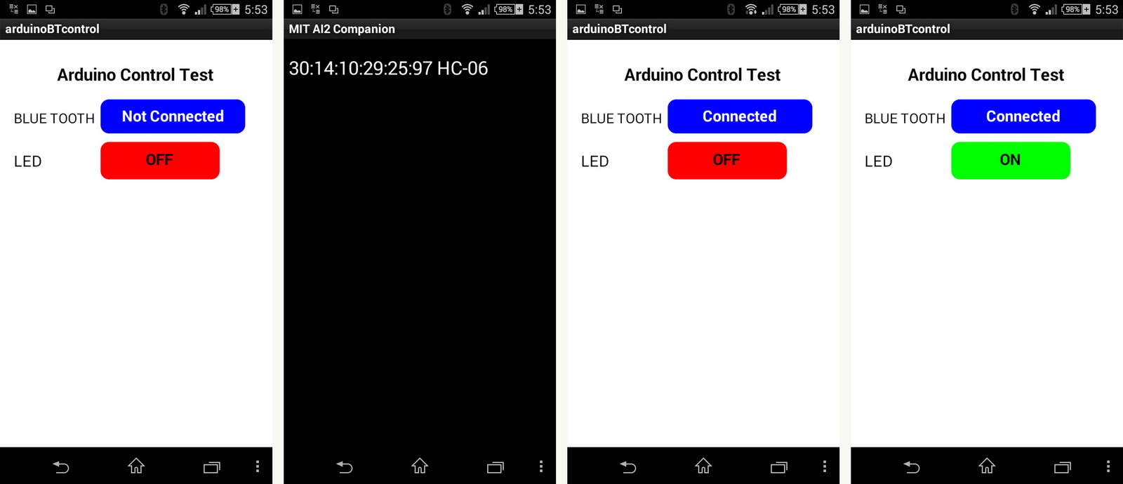
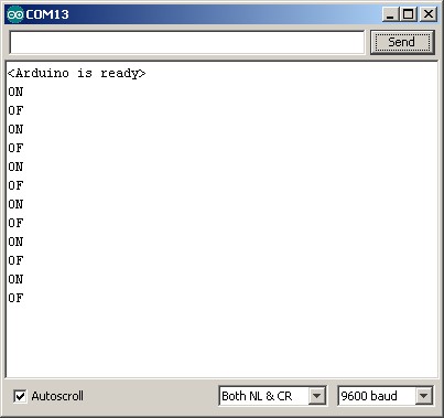
You can also open the serial monitor to see the commands as they are received
The steps involved are:
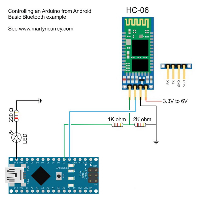
1. create a circuit that includes a Bluetooth module and a LED
2. create an Arduino sketch that can receive commands from the HC-06 and turn a LED on and off
3. create an Android app that sends commands over Bluetooth
The circuit
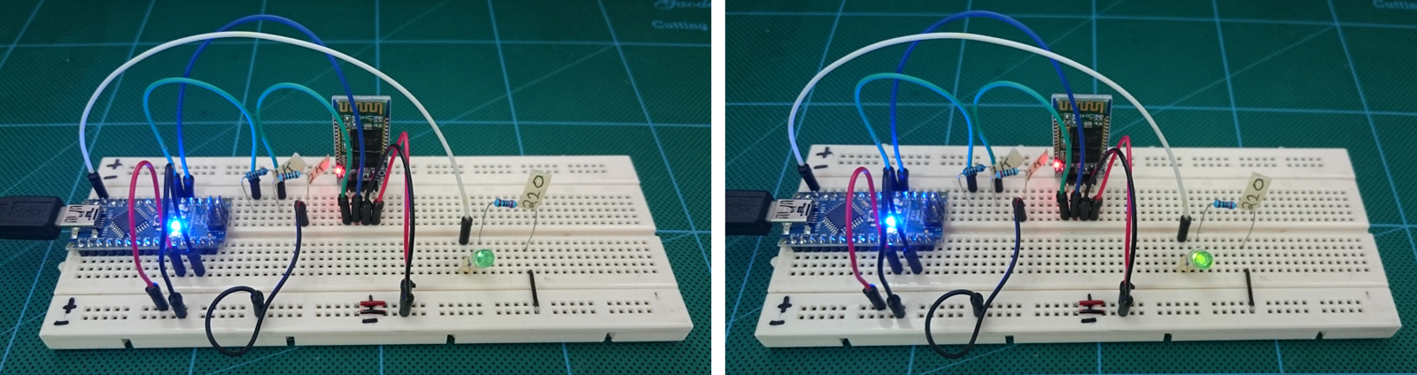
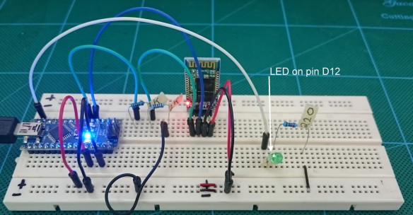
The circuit is the same as the one used in Arduino and HC-06 (ZS-040) except the addition of a LED + resistor connected to pin D12. I used a 220 ohm resistor because that is what I had to hand but similar values will be OK.
Based on ohm’s law; using a source of 5V, a green LED with a forward voltage drop of 2.2v and a forward current of 20mA a 150 ohm resistor is recommended. So any value from 180ohm to around 680 ohms will be OK.
Arduino Sketch
The sketch receives data from the Bluetooth module via software serial. It then checks the data for “ON” and “OF” commands. When “ON” is received the LED is turned on and when “OF” is received the LED is turned off.
To ensure that data is received correctly the data is surrounded by start and end markers. This example uses “<" and ">“. I use the function recvWithStartEndMarkers which was posted on the Arduino forum by Robin2. I simply copied the function and did not need to change it.
The recvWithStartEndMarkers() function takes at the data received from the serial connection and copies anything it finds between the start and end markers to the receivedChars variable. When it has found something it sets the newData variable to true.
In the main loop we keep calling the recvWithStartEndMarkers() function until newData has been set. When newData is True we know we have a new command so we call parseData() to deal with it. Inside parseData() we reset newData to false and the process continues.
void loop() { if (BTserial.available() > 0) { recvWithStartEndMarkers(); } if (newData) { parseData(); } } |
The full sketch:
// Bluetooth sketch HC-06_02 // Turn a LED on and off from an Android app // App can be downloaded from www.martyncurrey.com // // Pins // 2 Software serial - RX // 3 Software serial - TX // 12 LED boolean debug = true; #include <SoftwareSerial.h> SoftwareSerial BTserial(2,3); // RX | TX // Connect the HC-06 TX to the Arduino RX. // Connect the HC-06 RX to the Arduino TX through a voltage divider. // max length of command is 20 chrs const byte numChars = 20; char receivedChars[numChars]; boolean newData = false; byte LEDpin = 12; void setup() { pinMode(LEDpin, OUTPUT); Serial.begin(9600); Serial.println("<Arduino is ready>"); // The default baud rate for the HC-06s I have is 9600. Other modules may have a different speed. 38400 is common. BTserial.begin(9600); } void loop() { if (BTserial.available() > 0) { recvWithStartEndMarkers(); } if (newData) { parseData(); } } void parseData() { newData = false; if (debug) { Serial.println( receivedChars ); } if (receivedChars[0] == 'O' && receivedChars[1] == 'N' ) { digitalWrite(LEDpin,HIGH); } if (receivedChars[0] == 'O' && receivedChars[1] == 'F' ) { digitalWrite(LEDpin,LOW); } } void recvWithStartEndMarkers() { // function recvWithStartEndMarkers by Robin2 of the Arduino forums // See http://forum.arduino.cc/index.php?topic=288234.0 static boolean recvInProgress = false; static byte ndx = 0; char startMarker = '<'; char endMarker = '>'; char rc; if (BTserial.available() > 0) { rc = BTserial.read(); if (recvInProgress == true) { if (rc != endMarker) { receivedChars[ndx] = rc; ndx++; if (ndx >= numChars) { ndx = numChars - 1; } } else { receivedChars[ndx] = '\0'; // terminate the string recvInProgress = false; ndx = 0; newData = true; } } else if (rc == startMarker) { recvInProgress = true; } } } |
Android App
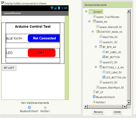
I created the Android app in MITs app inventor. This was fairly easy once I had figured out how to use Bluetooth.
The app is very basic, it simply sends commands. There are no checks to see if the Arduino has actually received the commands or not. The screen is also very simple; it has a button for connecting to Bluetooth and a on/off button to control the LED. The app uses a ListPicker to store the available Bluetooth devices which is not displayed on screen. It is initiated from the connect button.
The app has 4 blocks and a list:
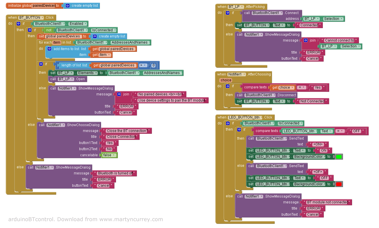
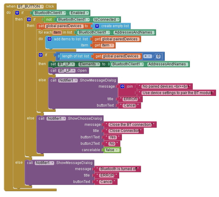
Block 1
This handles the connect button. When the button is clicked the block/function first checks to see if Bluetooth is enabled and then checks to see if there is already a Bluetooth connection. If Bluetooth is not turned on an error message is displayed. If there is already an active connection the user is asked if they would like to close it. The user reply is handled in Block3, Notifier1.AfterChoosing
If Bluetooth is on and there isn’t a current connection the paired Bluetooth devices are copied to the Bluetooth pairedDevices List. If the list has at least 1 item the contents of the list are copied to the ListPicker. The ListPicker is then activated to allow the user to select a Bluetooth device. I use the pairedDevices list so that I can count the number paired devices. I could not find a way of doing this when using just a ListPicker. If the list is empty an error message is displayed saying there are no paired devices.
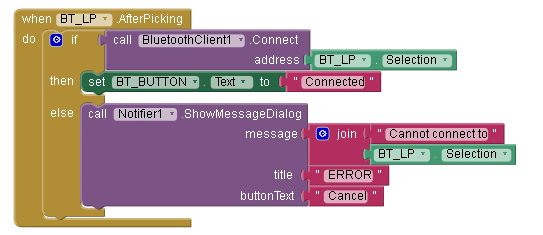
Block 2
Block 2, BT_LP.AfterPicking handles the List Picker after the user has selected one of the paired Bluetooth devices. It takes the selected item and tries to connect. If successful the text on the Bluetooth button is changed to “Connected”. If a connection cannot be established an error message is displayed.
Once a connection is established the app waits for the LED button to be pressed.
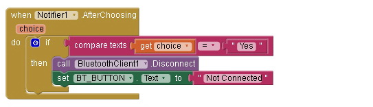
Block 3
Block 3 handles a Notifier dialogue that asks the user if they wish to close the connection
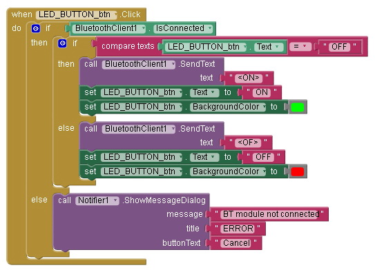
Block 4
Block 4, LED_BUTTON_btn.Click, handles the LED button. By checking the button text we can determine what command to send. If the text says “ON” then the LED is on and we need to turn it off so we send an “OF” command. If the text says “OFF”, the LED is off so we send an “ON” command to turn it on. The actual commands are “<ON>” and “<OF>”. The button text and background colour are updated to reflect the new LED status.
An error message is displayed if the LED button is clicked and there is no active connection.
Download
In part 2 we add 2-way communication and the facility to control the LED from the Arduino as well as the app.
Related:
Add an auto-connect function to an App Inventor app. https://www.martyncurrey.com/android-mit-app-inventor-auto-connect-to-bluetooth/
Hello, and first off thank you for this helpful blog. I was able to use it and make my own app to control my arduino through my Bluetooth shield. I’ve spent weeks before I came across this and within 1 night was able to get everything working. My questions now is my project has an auto off built into the code, is there any way to send a signal to the app to change the button states to show off. Thanks again
Have a look at https://www.martyncurrey.com/arduinobtcontrol/. This is the next step and includes sending data from the Arduino to the app.
The arduinoBTcontrol Android app has 3 command buttons that wait for an acknowledge signal from the Arduino before resetting. The way I do it is very basic but should be a good place to start.
dear Martyn, your simplified illustration and work is really appreciable, i have made this circuit and its working completely. but i have one query that can we made HC-06 as auto connect after we paired it first time ? actually its really annoying that every time we have to connect the phone to HC-06, likewise wifi can we do auto connect, please correct me and guide. thanks for your awesome work .
Hi prashant pitroda,
yes this is possible although I do not have an example to post at the moment.
The simplest way would be to change the address used in the “BluetoothClient1.Connect” block. At present the address comes from the Listpicker selected item “address BT_LP.Selection”. Change this to the address of your HC-06.
To take this further, I would allow the user to connect as per the above then add the facility to remember the paired & connected address. Then on start up, if there was a remembered address try to connect.
I will do and let you know. Thank you so much.
well thanks for your guidance….i have tried as you described and it works flawlessly.
thanks again
Hi,
First of all I really appreciate your work, it is really helpful. I want to auto-connect my phone to the HC-05, when the HC-05 is in range. I am trying to modify the aia file in this way:
http://kepfeltoltes.hu/150926/problem_www.kepfeltoltes.hu_.jpg
However, this is not working and I don’t know what the issue is.
The problem is you are still using the listPicker.AfterPicking event to connect. This means the list picker still needs to be used.
If you are auto connecting to the same address every time it would be better to put the blocks in to a screen initialize block. The Screen1.initialize block is called as soon as the app is started
I would also suggest adding checks to see if blue tooth is turned on and the bt address is in the list of paired devices otherwise you may get system error messages.
Sill trying, thanks for the advice.
I have added a new mini guide on creating an auto-connect app. See https://www.martyncurrey.com/android-mit-app-inventor-auto-connect-to-bluetooth/
This saves the address of the connected device and tries to connect when the app is next started.
I tryed a timer block (100ms):
http://kepfeltoltes.hu/151007/2015-10-07_212715_www.kepfeltoltes.hu_.jpg
And this code sends serial data from the arduino board to the phone when the LED is switched on/off:
if(dataFromBt == ‘3’){
bluetooth.print(ledState);
}
Now, the phone receive the status of the LED and update the LED button status (on or off) , but the app freezes if it doesn’t receive anything (phone is out of range).
I get a pop up message saying ” Error 516: Unable to write: Broken pipe ” and I can’t work with the app any longer.
Unfortunately app inventor doesn’t report when the bluetooth connection is lost. The only way I have found to get around this is to send regular “hello” signals from one device and then send a reply from the other device. If I get a reply then the connection is still active. If the connection is not active you get an error message.
You can trap the system errors using the “when Screen1.ErrorOccurred”. One of the values this gives you is the errorNumber so you can test for errorNumber = 516.
Problem solved. Thanks again!
The app inventor error handling block:
http://kepfeltoltes.hu/151013/error__handling_www.kepfeltoltes.hu_.jpg
How to solve
Thank you so much, it was really helpfull.
Just add an if errornumber = 516 and use the code on “then”
Hey! What do i have to do with that “if –> then”?
I mean, i have the same problem and i’ve created the block: When screen1.ErrorOcurred: do: if “get(errorNumber) = 516” then… then what?
Thanks!
sir I’m getting an” error 516: unable to write:[JSR82] write: write() failed. what should I do. BT is connecting to app but led is not responding.
PLZZZ….. help
Hello,
I have done a program with sliders in app inventor 2 to control RGB led strip and when i move the slider to change the color of the RGB led strip in serial monitor i get only symbols in serial monitor of the ardruino and not numbers. what is the problem?
Note: if i send a number from the bluetooth terminal on my android phone i receive the number correct in serial monitor of the ardruino
2 things to check.
1. the baud rate between the Arduino and the BT module
2. the format of the data being sent. It could be you are sending actual values (1,2,3 etc) and then treating them as ascii on the Arduino.
Convert the value from the sliders to ascii then send. The format I use is <Srrrgggbbb>
S for slider
rrr – the decimal red value in acsii
ggg – the decimal green value in acsii
bbb – the decimal rblue value in acsii
See https://www.martyncurrey.com/arduinobtcontrol/. I created my own sliders but you can use the built in sliders exactly the same.
Hi guys , I have a proble that is about error message is on the screen since longer time and I want to decrease this time and after the message seems , it should lost on the screen, please helppp
what error message are you referring to?
“”Broken pipe “”or “”error 502″” like these. I want to when this message shown on my phone ,this message shouldn’t long time on the screen ,it must take about 5 second but it takes too longer time ,what can i do please help
Hi Martin!
I would like to ask, at the block 1, where did you get the global pairedDevices? I would like to do a similar program which control more led. If I want to do that the led is only on when the user pushes the button than should i use the “when led_button.touchdown”?
Thanks in advance!
global pairedDevices is a global list – see “the app has 4 blocks” image.
If you want the LED to come on only when the button is held down then you would use the touchdown and touch up events. Touch down to turn on the LED, touch up to turn off the LED.
I use this method in the ardionoBTcontrol example, see https://www.martyncurrey.com/arduinobtcontrol/
What a silly I am, now I see it.
Thanks for your quick reply and help :)
Hy Martin!
Can I ask you something more? I did what you suggested, and it works fine, but can I make the platform somehow multi touch? I mean how can I setup that I want to turn on two leds on the same time?
Thanks in advance!
Do you mean have more buttons to control more LEDS?
If yes then you just need to extend the app and the commands used.
In the app add extra buttons; some like LED1, LED2, LED3 etc.
When each of these are clicked send the commands
<L1ON> or <L1OF>
<L2ON> or <L2OF>
<L3ON> or <L3OF>
In the Arduino sketch, in the parseData function check receivedChars for the commands and set pins HIGH or LOW accordingly.
As the commands get longer it would better to use strcmp.
if (strcmp (“L1ON”,receivedChars) == 0)
{
digitalWrite(LED1_PIN,HIGH);
}
if (strcmp (“L1OF”,receivedChars) == 0)
{
digitalWrite(LED1_PIN,LOW);
}
if (receivedChars[0] == ‘O’ && receivedChars[1] == ‘N’ ) { digitalWrite(LEDpin,HIGH); }
if (receivedChars[0] == ‘O’ && receivedChars[1] == ‘F’ ) { digitalWrite(LEDpin,LOW); }
if (receivedChars[1] == ‘O’ && receivedChars[1] == ‘N’ ) { digitalWrite(LED1,HIGH); }
if (receivedChars[1] == ‘O’ && receivedChars[1] == ‘F’ ) { digitalWrite(LED1,LOW); }
can i use this for more LED?
See part 2 and part 3
I mean to push two button at the same time, and both LEDs turn on. So, kind of multitouch. It realize when we push two button on the same time
Sir, thankou very much for your examples, I just bought an HC-06 and followed your basic setup page, works flawlessly, now I am trying this one but I am pleased to have found so much infos in one place.
You are the man!
Thank you sir for sharing this article its quite helpful.
how to get the call BT_getNewData??
There is no BT_getNewData in this example.
For receiving BT data on the Android device see part 2 and part 3.
I may have missed the instructions, but how do I install the apk file on my phone once I downloaded it from your site please Martyn?
Ah wait, Dr Google to the rescue. I found a way on stackexchange, where it was suggested I email the apk to my Gmail, open the mail on the phone, download the apk from the email. Then it recognised it as an apk and offered me the choice to install, which I did…. works a treat, thanks for this tutorial.
(Is that how you would download an apk?)
Jim
I would normally copy the apk using a usb cable. After it is copied I using a file manager app to click on the apk and install it. You need to allow install from untrusted/unknown sources.
i need use code with arduine mega , but i can not do it . please help me . with RX and TX
Hi
I just found your website and decided to give App2Inventor a try. I love it. I am studying for OCAJP and was already dabbling a little in Android studio. the blocky code makes coding even complex tasks a breeze. Really enjoyed. Quick question tho. Within a short couple hours I was able to get my hello world pet the kitty upgraded to a bluetooth app that controls my leds with all of the functionality that my code allows. However I noticed that in order to use the bluetooth logic I needed to have the bluetooth client embedded “hidden” in the second screen I am using. I am using the same logic for buttons to the second screen as I did on the first with no errors ie if button press if serial connect send serial text send this char array etc., however the buttons arent working on the second screen and when I go back to the main screen I find the bluetoothconnection has failed. I looked into this but a google search leads me to app2inventor setup FAQ’s and general bluetooth nonsense for starting out. do you have any idea why I am losing my bluetooth connection going between the 2 screens I am using? thanks for any response
Bluetooth is associated with one screen only. This means if you embed it in screen2 it is only available in screen2. I work around this by using pseudo screens. See https://www.martyncurrey.com/app-inventor-2-pseudo-screens/
Hi!
I have some problems with my bluetooth connection based app.
The app is working well but after a minute I get a message from the app saying ” Error 516: Unable to write: Broken pipe ” and I can work with the app but bluetooth module disconnects from my mobile.
I think it could be a problem related to the baud rate, I’m using Serial.begin(38400) in my Arduino code and the bluetooth module is also configured at 38400 b/s but i don’t know, my app sends 2 bytes number (two “Call BluetoothClient send1byteNumber” one after another) and maybe the baud rate is too much.
Thanks
The baud rate is used for the communication between the Arduino and the Bluetooth module only.
The baud rate used by the BT module to talk to the mobile phone is automatic and handled by the phone. You cannot change this.
The Broken Pipe error means you have lost the connection. Are you moving around or are you using the module in a wireless noisy environment?
You can trap the errors with the Screen1.ErrorOccurred block.
Test for error 516 and then try to reconnect. Or have a popup that says the connection is broken and would you like to try and reconnect.
HI !
sir how to run this ino code in arduino mega
sir how to make code for esp8266 like this
Can u please get me block for 4 nos botton for BT to on off for 4 nos led.
Genial, Muy buen articulo, mil gracias.
Amazing, very nice tutorial, Thanks so much…
Regards.
Danilo Bolaños.
Costa Rica.
Hi
i like this project. I want to do someting and need that arduino remember led after disconeting the power. I know that needs eeprom but I dont know how to write it in to te sketch. If you can help me and write in to the scatch, Thank you
Hi I have the solution for the , broken pipe or error 516 , 517. The solution is use this blocks to prevent errors showing on the screen.
( İf BT working and errors making problem then use it. I guess it shuts all errors on the screen xD so you will not be able to see android errors anymore but still the programs all BT options working which is enough :) )
By the way the website is my friend’s website so help him out, there is so much free course notes for computer engineering :D
When screen1.ErrorOccured
Do for each item in list get errorNumber
Do close screen with value result get errorNumber
Good day to you !
just wanted to say a MASSIVE Thank-You for showing how to design an app, i guess ya can teach an old dog new tricks haha !
i find it very difficult to get me head around these things so when i tell you that its been a pleasure to work thru your tutorials, all info needed, sketches, schematics, code, online website converter links etc, youve thought of it all !
Well done and once more, thank you ever so much for all the diligence, hard work and awesome ingenuity for making your blog, its totally awesome !
have a great day :)
kindest regards,
Anil Jr ;)
Thank you for the kind words and glad the site is helpful.
It is never too old to learn something new.
Hi Martyn,
How about if i want to control the brightness of Leds? I have tried using the slider in tht mit app however, it didn’t work.. help me figure this out please. Thanks
Hello
I want to do like this but via wifi , do we have such command like wifi.send or…?
Have a look at the posts on the ESP8266 starting with https://www.martyncurrey.com/esp8266-and-the-arduino-ide/
Hi,
I love your post and thanks for information.
I would want to know how you could send bluetooth signals to a smartphone with the push buttons, in your video on youtube. (https://www.youtube.com/watch?v=aL-rZLptRHQ)
I want to send bluetooth signals to a smartphone through buttons on the circuit as you did in the video.
If I connect the bluetooth module on D2, D3 and two buttons on D5, D6, would the signals from buttons (if I push them) go to the bluetooth module? (for controlling the APP)