In this final part of this series I add a network connection manager, add a couple of extra functions, add a stand, fix a couple of problems.
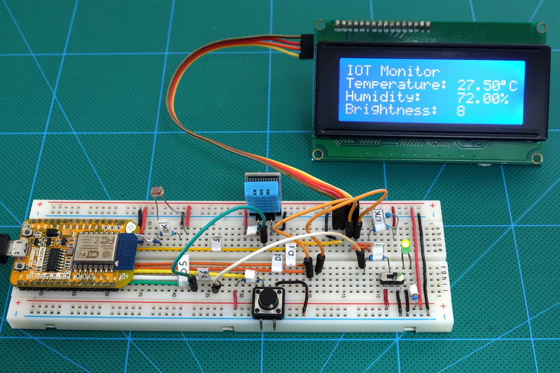
Here is the final project.

Part 1: The Esp8266 and setting up the Arduino IDE
Part 2: Control an LED from a web page using Access Point Mode (AP)
Part 3: Control an LED from a web page using Access Station Mode (ST)
Part 4: mDNS
Part 5: wifiManager
Part 6: JavaScript and AJAX
Part 7: More Controls. 3 LEDs
Part 8: Auto Updating Webpage
Part 9: First steps with Websockets
Part 10a: IOT Monitor part 1 – webpage
Part 10b: IOT Monitor part 2 – enhancing the webpage
Part 10c: IOT Monitor part 3 – adding a LCD
Part 10d: IOT Monitor part 4 – the final project
At the moment the LCD is working and the webapp is working as long as we know the IP address to go to.
When I completed the last post I had thought all the hard parts were done, and this time I just needed to add Wifi Manager, add mDNS, and add a stand. This turned out not to be the case. Wifi Manager didn’t work and because of the LCD mDNS wasn’t required. The stand turned out nice though. As I played with the code I found several things that needed addressing.
So what are the problems?
- The IP address is hard coded which makes it difficult to connect to other networks.
- Even if there was an easy way to connect to different networks, how do we get to know the IP address.
- How to stop a connection and then connect to a different network.
- Websockets do not start straight away and when data is sent too early it gets ignored. This then means the webpage does not get updated until the timer fires. This can be anything from minutes to hours depending on the update frequency used.
As I worked on this part of the project things kept developing and changing. I found issues I wanted to fix, things I didn’t like or thought of better ways to do something. It didn’t help that I developed the sketch organically without a clear plan and I would move code around and rename variables on the spur of the moment. I also forgot to record the changes and simply went with the flow. All this means the final sketch, while based on the previous ones, does not follow the usual simple next step I normally use and I have therefore decided it would be better for me to present the final project and describe it as it is. Hopefully explaining what changed or why I did something in the particular way.
IP Address
At the moment, the network credentials are hard coded and to get the IP address the ESP8266 has to be connected to a computer with the serial monitor open which is not good for a stand alone project. To make this project stand alone we need a way of allowing it to connect to any network without reprogramming the ESP8266. We also need a way of knowing what IP address to go to once the device is connected. Unfortunately things conspired against me and what was supposed to be simple turned out not to be.
WiFi Manager
To allow easy connection to a local network I had planned to drop in Wifi Manager and move on. Things didn’t go as planned though. As soon as I added the Wifi Manager Library the sketch started mis-behaving and crashing. I also realized WiFi Manager didn’t do exactly what I wanted.
The two main issues I faced with connecting to a network:
- WiFi Manger didn’t do as it promised (or more likely, didn’t do what I thought it was supposed to do).
- It made the sketch unreliable. With WiFi Manager included it kept crashing.
- I could not, not connect to an active previously connected network. This meant I could not easily change networks.
I tried a few different versions of WiFi Manager then started looking for alternatives and while playing with alternatives I started to create my own solution, Simple Connection Manager (SCM) was born. The initial idea was to create a simpler, lighter version of WiFi Manager but as I experimented I got carried away and it became a full replacement (the problem with writing code organically rather than following a plan).
Simple Connection Manager
SCM is not a library (although I may try turning it in to a library later) it a set of functions that can be dropped in to any sketch. I have been using it for a short while it is working well and seems to be reliable. I dare say somebody will manage to break it though. A benefit of having the code as part of the main sketch is it is easy to add to. In this project I added code to use the LCD. I keep SCM on its own tab away from the main sketch. This makes it easy to add to other project.
The code is mostly my own but not 100% unique and I took a lot of inspiration from the various WiFi Manager libraries that are available. I suppose the main things to note are:
1. There is no auto connect functionality, this is handled natively by the ESP8266 any way, and it is up to the user/code writer to check for saved credentials before calling SCM. This is a technique I have been employing with WiFi Manager because I never found WiFi Manager’s auto connect that reliable.
if (WiFi.SSID() != "") { try to connect } if ( WiFi.status()!=WL_CONNECTED ) { call SCM } |
If there are saved credentials then try to connect. If the connection fails or there are no saved credentials call SCM.
2. SCM cannot yet handle custom AP mode IP addresses without adding code to the functions. It is not difficult to do though.
What started out as a supposed lite connection function became a fully featured connection manager but the name remained. I don’t explain the code is depth here (I will make a separate post) but I have added a lot of comments and debugging serial print statements to help explain what the code does. The version here uses the LCD which other projects may not have.
Easily Change Networks
As I progressed with SCM I discovered minor issues and annoyances so I kept adding things. When not using hard coded network credentials and WiFi Manager there is no easy way to change networks once a network have been saved.
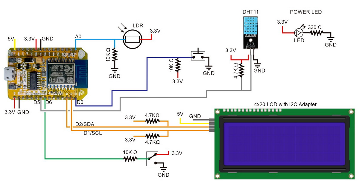
The ESP8266 automatically connects to the last successfully connected network. If you want to change networks and the current network is still active you have to disable it, let the ESP8266 fail to connect and then connect to a different network. This normally is not an issue since in most cases you don’t keep changing networks when in the same location. However, I have 4 networks (2 I use for IOT) and I could not easily change between them without reprogramming the ESP8266 (deleting the saved credentials) or turning off the network and letting the connection process fail. This meant I needed a way of activating the connection portal on command. I did this by adding switch. If the switch is closed on start up the saved credentials are erased with a WiFi.disconnect() command which then means the connection manager is called. Check the circuit below to see how the switch is connected.
The process/flow is:
- Check to see if the switch is closed.
- If the switch is closed erase any saved credentials.
- If there are saved credentials start the ESP8266 wifi and try to connect.
- Check the connection status.
- If the ESP8266 is not connected open Simple Connection Manager.
// If there are any saved credentials the ESP8266 will try to auto connect even if you haven't asked it to. // WiFi.disconnect() disconnects (if connected) and erases saved network credentials. // It is an easy way to reset saved credentials. if ( digitalRead( pinSWITCH2)== LOW ) { WiFi.disconnect(); } |
// if not connected open the wifi connection page if ( WiFi.status()!=WL_CONNECTED ) { // Simple Connection Manager return value: // 0 = no networks. 1 = have networks but connection failed. 2 = connected to local network. byte connectionResult = simpleConnectionManager(APssid,APpass); ~ ~ ~ |
Get the IP address
With the ESP8266 (and any other IOT device) that connect to a local network, there is always the problem of getting the IP address. When using AP mode and connecting to the ESP8266 directly this is not an issue as the IP address should be published somewhere or will likely be the default (such as 192.168.4.1). When the device uses Station Mode and connects to a local network things are a little trickier. Almost all ESP8266 guides online never get past using the Serial Monitor and this is not always practical.
 This project has a LCD so the obvious choice is to display the local network IP address on the lcd. I can do this easily at start up but what happens if I need the IP address after the monitor has started? My solution is to use the same button switch I am using to reset the saved network credentials. Once the device is running and showing the IOT monitor, closing the switch shows the local network IP address on the LCD.
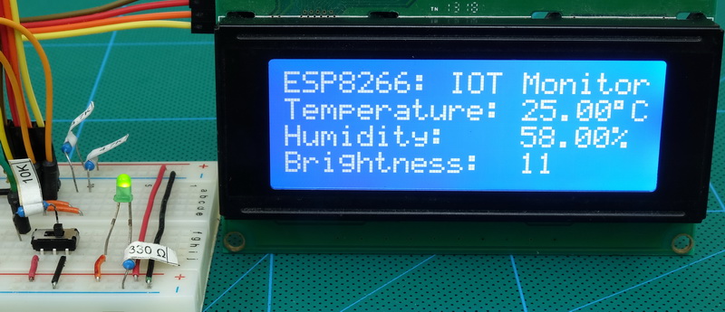
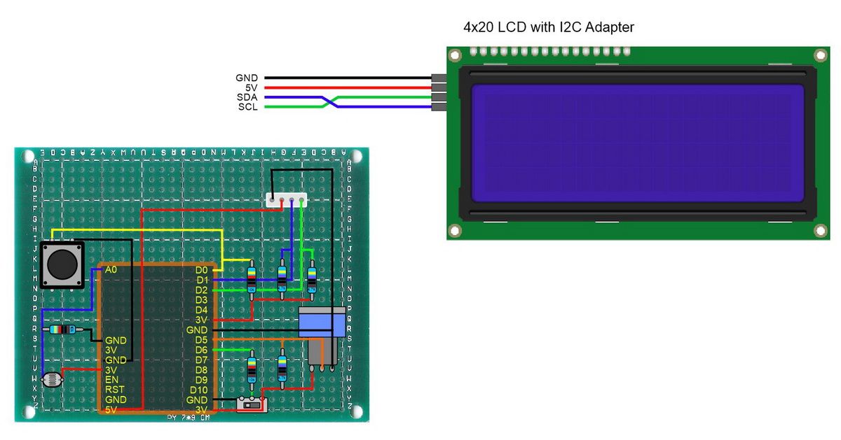
Circuit
I have removed the power LED and added a push button switch to pin D0. The NodeMCU already has a small push button switch on the board that is connected to D0 but a larger one makes it more convenient. Pin D0 is connected to an on board LED and when the pin is connected to GND the LED comes on. This is handy to show when the switch is closed. One thing to note; D0/GPIO16 is HIGH on start (and needs to be HIGH on boot) so I am using normally HIGH rather than a normally LOW. The pin is pulled HIGH with a 10K resistor and connects to GND when the switch is closed. This new switch is used to either erase the saved network credentials or show the network connection details on the LCD.
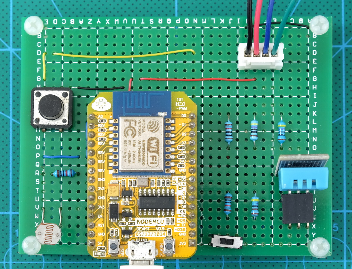
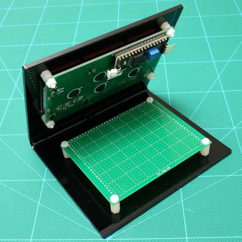
Here is the perf board.
Sketch
The sketch uses 3 tabs:
– ESP8266-10D_sketch01.ino
– SCM.h
– webpage.h
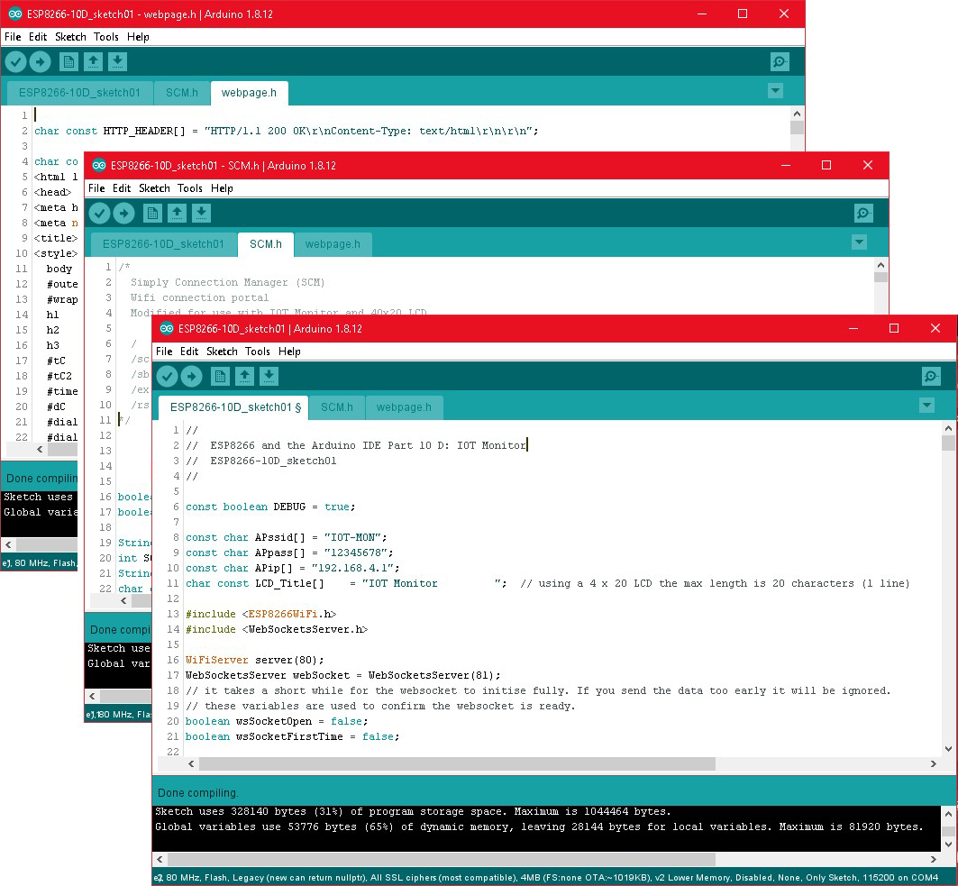
ESP8266-10D_sketch01.ino is the main sketch and where all the logic resides
webpage.h is the html for the IOT Monitor webpage
SCM.h is Simple Connection Manager
Download at the bottom of the page
Key features
SCM.h and webpage.h are added to the main sketch using include statements.
// Simple Connection Manager. add the Simple Connection Manager file #include "SCM.h" // HTML file for the IOT Monitor. add the main HTML file for the IOT Monitor #include "webpage.h" |
The push button switch is used at start up to clear any saved network credentials. At the top of the setup function the switch status is checked and if it is LOW the WiFi.disconnect() command is called. This disconnects a current connection and also wipes saved network details.
// If there are any saved credentials the ESP8266 will try to auto connect even if you haven't asked it to. // WiFi.disconnect() disconnects (if connected) and erases saved network credentials. // It is an easy way to reset saved credentials. if ( digitalRead( pinSWITCH2)== LOW ) { WiFi.disconnect(); } |
The next step checks to see if there are any saved credentials. If there are the ESP8266 attempts to connect.
if (WiFi.SSID() != "" ) { // uses AP and STA mode together // This means you can access the webapp via the local network or by connecting to the ESP8266 directly WiFi.mode(WIFI_AP_STA); WiFi.begin(); // time out after 10 seconds (500ms * 20) byte count = 0; while ( (WiFi.status()!=WL_CONNECTED ) && ( count< 20) ) { if (DEBUG) { Serial.print(F(".")); } count++; delay(500); } |
If there are no saved network details or the connection attempt failed the SCM is called.
if ( WiFi.status()!=WL_CONNECTED ) { // Simple Connection Manager return value: // 0 = no networks. 1 = have networks but connection failed. 2 = connected to local network. byte connectionResult = simpleConnectionManager(APssid,APpass); |
The IOT Monitor uses AP mode and STA Mode together. This means if SCM fails to connect the ESP8266 AP mode is left open and the ESP8266 can be connected to directly using the default IP address 192.168.4.1
Web Sockets
After the connection process is finished the webserver and websockets are started and a websocket call back is created (a function that is called when there is a websockt event).
// start the websocket webSocket.begin(); // webSocketEvent is the function to call when there is a websocket event webSocket.onEvent(webSocketEvent); |
There is only one important event. receive text so this is all that is checked:
void webSocketEvent(byte num, WStype_t type, uint8_t * payload, size_t length) { if(type == WStype_TEXT) { ~ ~ ~ |
Web sockets do not start straight away. It takes a short while after the webpage is loaded for the websocket to initialise. This means, if the sensor data is sent as soon as the webpage loads the data will be lost but the sketch will not know it. This then means the data would not be updated again until the sensor update timer fires. This then means there will be a blank website.
By checking the websocket start event we can wait until we are sure the websockets are running before sending the first sensor data. After that we update based on the update frequency. Without this we have a blank website until the timer kicks in.
In the website. When the web socket is started an onopen event is fired. This is used to send a “#” code to the ESP8266 to let it know the web socket is ready to receive data.
Socket.onopen = function() { console.log('WS open'); Socket.send('#'); } |
On the ESP8266, when the code is received the variable webSocketIsOpen is set to TRUE and the sensor data is updated.
webSocketIsOpen is used to tell the rest of the sketch if it can use the web socket channel or not. When webSocketIsOpen is FALSE the sensor data is not sent to the website.
if (payload[0] == '#') // the websocket on the webpage has started { if (DEBUG) { Serial.println(F("websocket started\n")); } webSocketIsOpen = true; updateSensors(webSocketIsOpen); } |
if ( upDateWebPage && wsSocketOpen) { webSocket.broadcastTXT(data); } |
Serving the webpage
When there is a request from the client, the request is checked to see if it for the main page and if it is the page is served. Any other request is ignored. I am not using ESP8266WebServer library so I need to extract the URI manually from the first line of the request. If you need a refresher on requests revisit part 2.
// if client is true then we have a request if (client) { String REQUEST = client.readStringUntil('\r'); int URI_START = REQUEST.indexOf(" "); int URI_END = REQUEST.indexOf(" ", URI_START+1 ); if (URI_START != -1 && URI_END != -1) { String URI = REQUEST.substring(URI_START+1, URI_END); URI.toLowerCase(); // IOT Monitor only has one page so we are only interested in root. Anything else can be ignored. if ( URI == "/" ) { client.flush(); client.print( HTTP_HEADER ); client.print( HTML_1 ); // a new page means a new ws service. Reset the ws flag and wait for the ws start message webSocketIsOpen = false; } } } |
If the correct request is received the webpage is sent and webSocketIsOpen is reset to false.
Display the network information
I mentioned above that I am using the button switch to show the network information on the LCD. When the switch is closed the screen switches to the network information.
After the check to see if there is a new request the button switch is checked and if it is pressed the connection information is displayed and a timer started. The timer is used to switch the display back to the sensor data.
To stop the issues arising when the switch is kept closed a status variable is used. This is a fairly standard technique and if you want to know more about this check out the Switching Things On And Off With An Arduino post.
boolean btnSwitchState = digitalRead( pinSWITCH2); if ( btnSwitchState == LOW ) { if (btnSwitchPrevState != LOW) { displayInfo_StartTime = millis(); displayInfo_Active = true; btnSwitchPrevState = LOW; lcd.clear(); if ( WiFi.status()== WL_CONNECTED ) { lcd.setCursor(0, 0); lcd.print(LCD_Title); lcd.setCursor(0, 1); lcd.print(F("Connected to")); lcd.setCursor(0, 2); lcd.print( WiFi.SSID() ); // length of SSID is not checked lcd.setCursor(0, 3); lcd.print(WiFi.localIP()); } else { lcd.setCursor(0, 0); lcd.print(LCD_Title); lcd.setCursor(0, 1); lcd.print(F("Connect directly")); lcd.setCursor(0, 2); lcd.print(APssid); lcd.setCursor(0, 3); lcd.print(APip); } } } else { btnSwitchPrevState = HIGH; } |
A check is made to see if the network data is being displayed and if it is time to return to the IOT Monitor
// timer to return to sensor data display if ( displayInfo_Active ) { if (millis() - displayInfo_StartTime > displayInfo_TimeActive) { updateSensors(false); // false = update the LCD only. displayInfo_Active = false; } } |
Which Temperature Scale?
A 2-position switch connected to pin D6 is used to determine the temperature scale to use; either Fahrenheit or Celsius. HIGH = Fahrenheit. LOW = Celsius.
boolean const CELSIUS = false; boolean const FAHRENHEIT = true; |
//check the TempScaleSwitch. See if the user has changed the scale // if the scale has just changed then update the sensors straight away switchPinState = digitalRead(pinSWITCH); if (switchPinState==FAHRENHEIT) {whichTemp = FAHRENHEIT;} else {whichTemp = CELSIUS;} if (whichTemp != oldTemp) { oldTemp = whichTemp; updateSensors(webSocketIsOpen); } |
If the scale has changed the sensor data is updated. The value of the variable whichTemp used in the sensor update function to determine which scale to display.
Sensor data update
The last part of the loop() function checks to see if it is time to update the sensor data.
// timeNow is used to determin if it is time to update the sensor values. timeNow = millis(); // see if it is time to update the sensor values if (timeNow - sensorUpdate_TimePrev > sensorUpdate_Frequency) { // webSocketIsOpen is either true or false // updateSensors(false) means update the LCD only // updateSensors(true) means update the webpage and the LCD displayInfo_Active = false; // reset the display net credentials timer. Just in case it is ruuning. updateSensors(webSocketIsOpen); // true = update the website as well. } |
If it is time displayInfo_Active is reset, just in case the network information is being displayed, and the updateSensors() function is called. The updateSensors() function is the same as in previous posts.
That’s it for the main parts of the code. I have included many comments to try and explain what is happening and it is worth looking through the sketch.
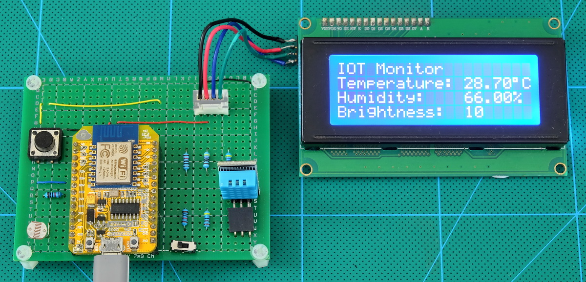
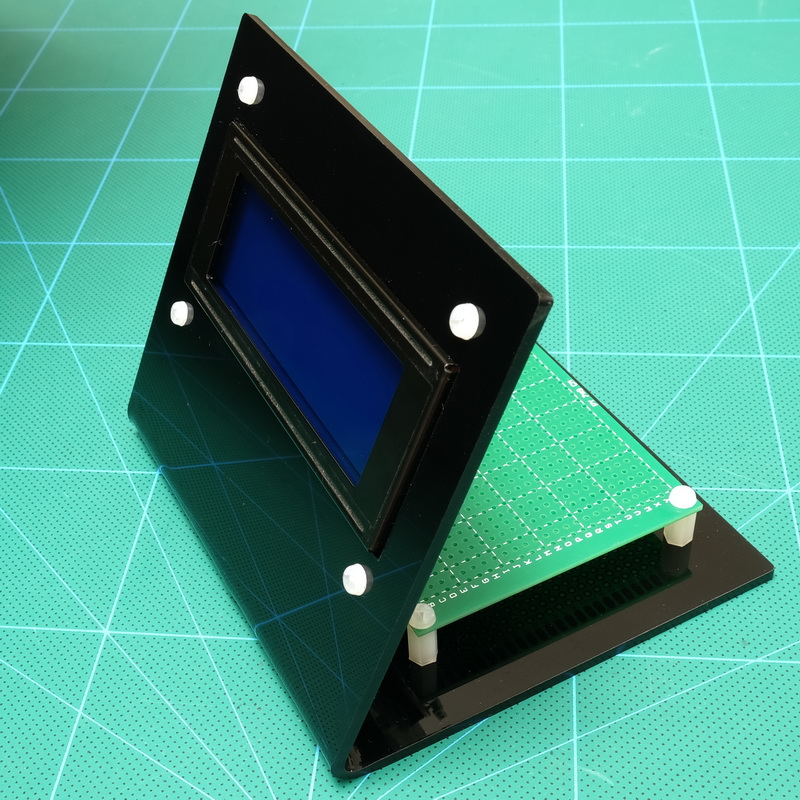
The Stand
The stand is made from black acrylic and was made for this project. It accommodates a 40×20 character LCD screen and a 7x9cm perf board. It is unlikely you will have the same stand and anything suitable can be used.
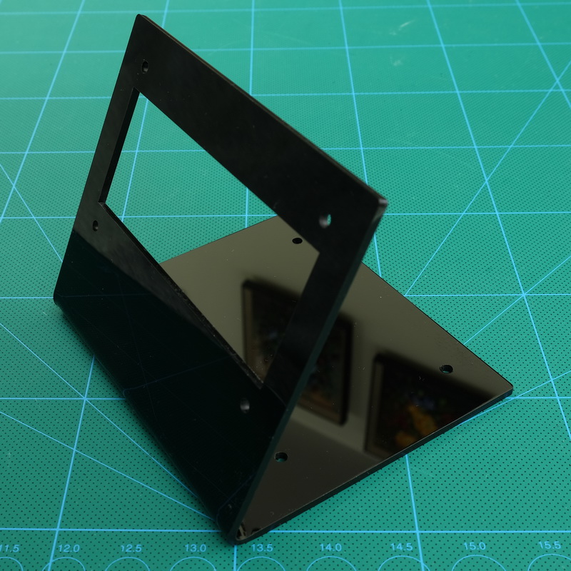
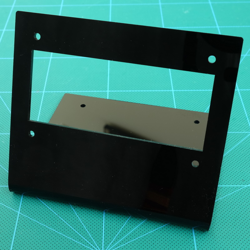
The stand has a hole for the LCD and holes to mount a 9cm x 5cm protoboard.
I also made a slightly smaller version for a 16×2 LCD which I will use in another project.
In Use
The first time the IOT Monitor is used there are no saved credentials so the SCM is called:
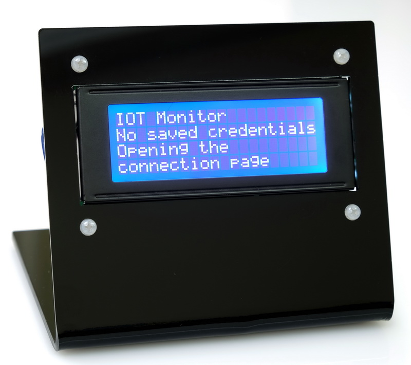 No saved credentials.
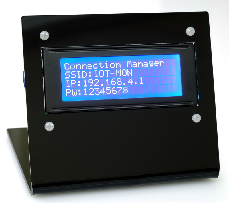
 The connection details for SCM are displayed. The user connects to the network and ip address shown.
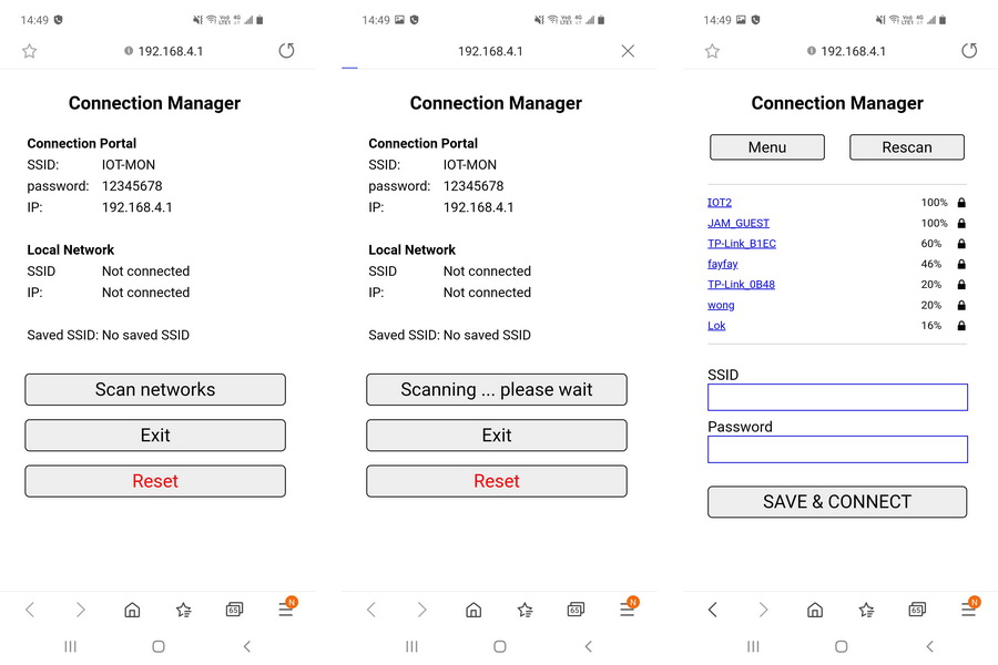 Simple Connection Manager
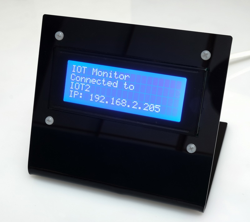
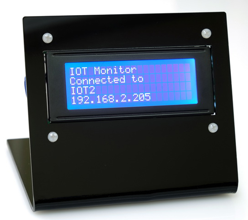
 If a connection is made the local network connection details are displayed. This shows the local network SSID and the IP address.
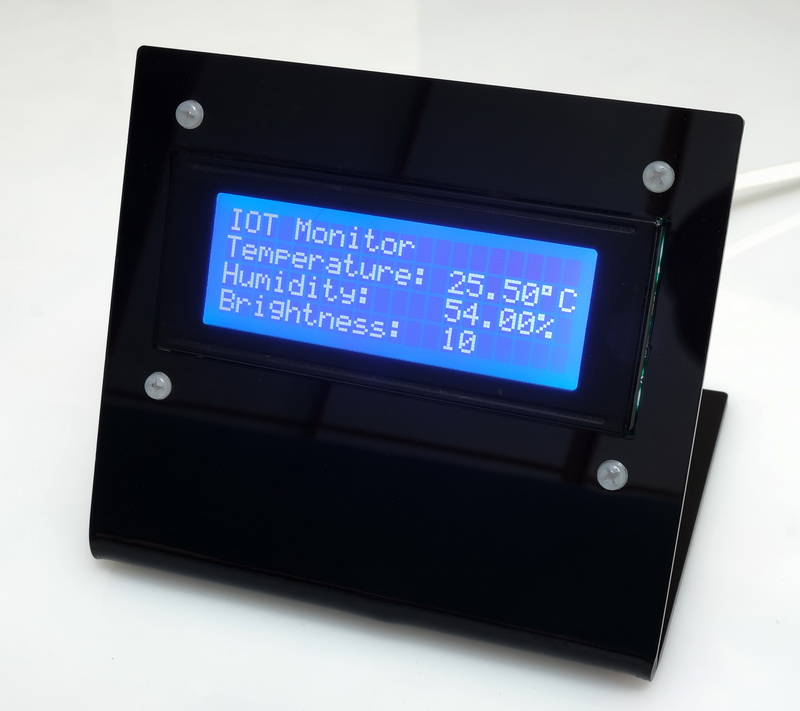
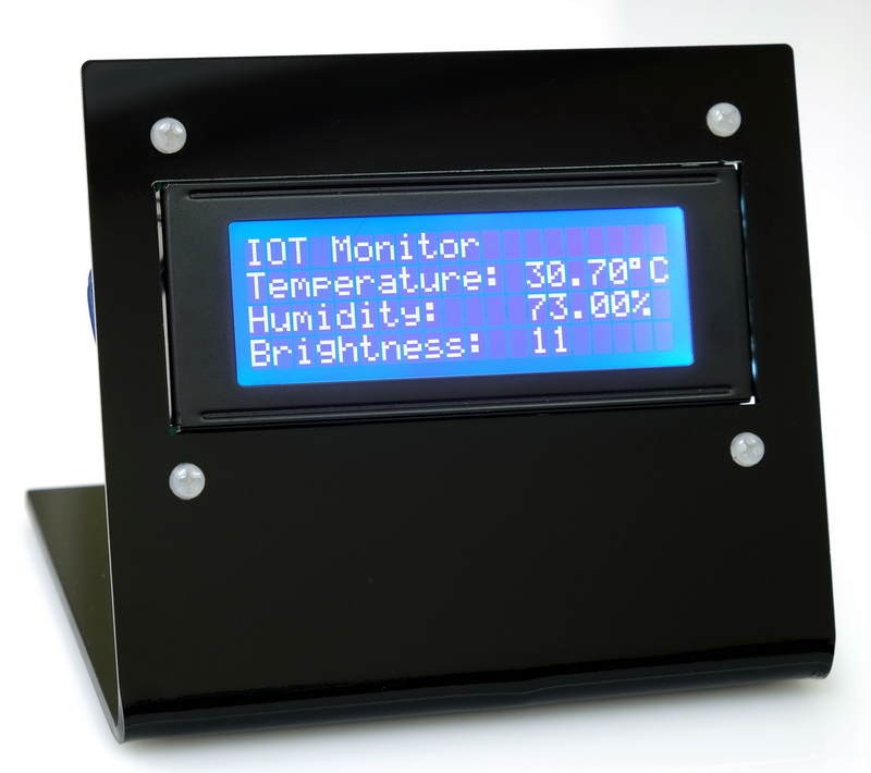 When the connection manager is closed the IOT Monitor data is displayed.
 The next time the IOT monitor is used it should have saved credentials and will try to connect automatically.
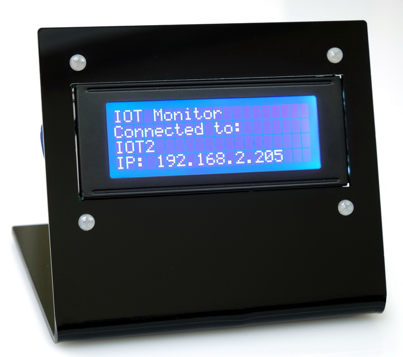
 If the connection is successful the connection details will be shown.
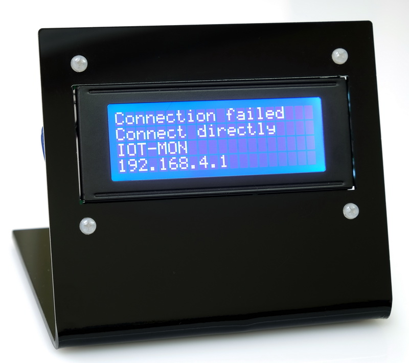
 If the connection fails
 the connection manager is started.
Simple Connection Manager may fail to connect
 No networks found.
 Could not connect to the selected network.
If a connection to a local network cannot be made the IOT Monitor defaults to AP mode and allows the user to connect directly.
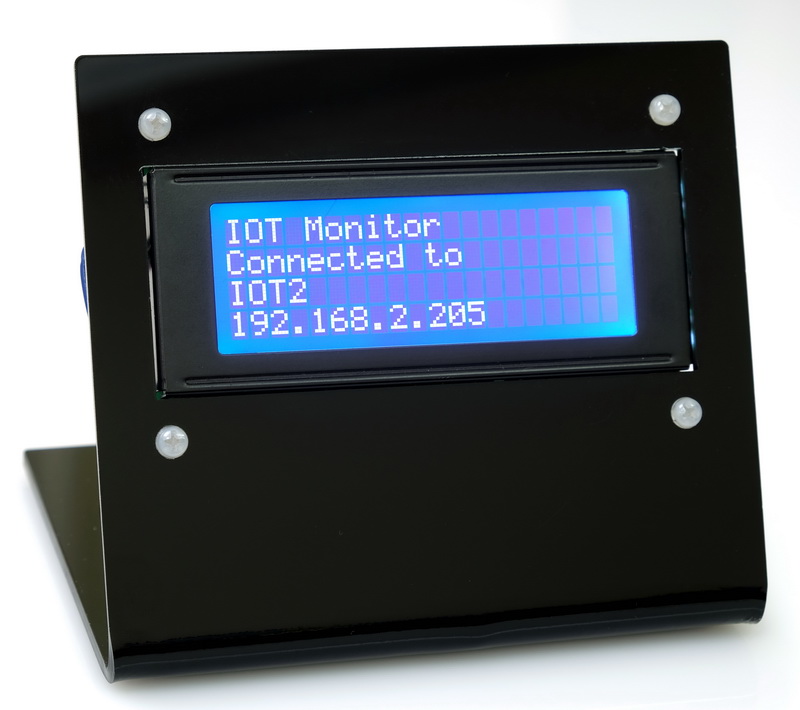 After the IOT Monitor is connected, pressing the push button switch shows the connection details on the screen.
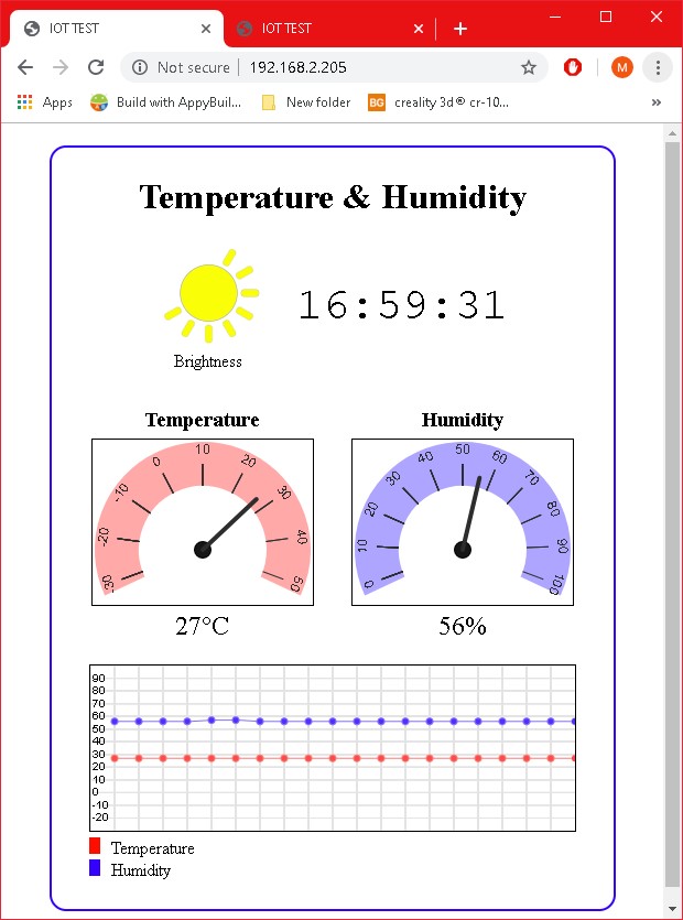
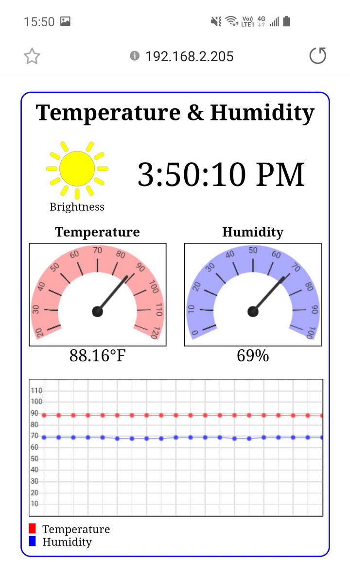
And here is the IOT-Monitor webpage
Download
Download the final sketch: ESP8266-10D_sketch_001_Final.zip
This concludes the ESP8266 series of posts. Hope you found them helpful.
Hello, I put this all on an ESP32 Feather and HD44780 LCD.
Seems to work except for the fact it will not serve webpages correctly. Looking at the debug info, it looks like it’s trying but the device trying to load the page says, “192.168.4.1 didn’t send any data”.
Serial started at 115200
No saved SSID
Starting SCM
Simple Connection Manager
LocalIP = 0.0.0.0
APIP = 192.168.4.1
APWiFi status = 255
SCM server started
connectionResult = 9
Server started
websocket initialised
45|23.20|73.76|48|C
Scale changed to FAHRENHEIT
45|23.20|73.76|48|F
45|23.20|73.76|48|F
dhcps: send_offer>>udp_sendto result 0
45|23.20|73.76|48|F
Request = GET / HTTP/1.1
URI = /
Page served
Request =
Request = GET / HTTP/1.1
URI = /
Page served
Request = GET / HTTP/1.1
URI = /
Page served
Request = GET / HTTP/1.1
URI = /
Page served
So, I can see the request on the serial debug port and it looks like it’s trying to send it but I can’t figure out why it’s not sending.
Thoughts?
Thanks,
Jeff
Forgot to mention (not that it matters) I changed the LCD driver to work with mine.
Hello, many many thanks for this tut, It is awesome and you are the best one.
I m testing your code and I wonder if It be possible use several web pages and using an arduino mega to have more adc.
I was looking for how to use ajax over AT commands or how to program the esp8266 throgh arduino.
Can you point me in the correct way please? :)
For multiply websites, there are 2 main methods, either parse the request manually or more easily use the webserver library. The page url is in the request but you need to isolate it. The webserver library does this for you.
If your ESP8266 has the AT firmware my suggestion is to change and use the Arduino IDE to program it. This turns the ESP8266 in to an Arduino with wifi. Using the ESP8266 with the Arduino overwrites the AT firmware though.
Ok thanks but, regard to this last paragraph, Either changing the ESP firmware, i won´t be able to use more ADCs. I mean, the point is using an Arduino Mega to have a lot of I/O and ADCs.
The ESP8266 can be used along side an Arduino exactly the same as you have it now. This is how I use them in many projects; I have all the wifi stuff on the ESP and everything else on the Arduino. The two talk using serial.
The difference is you have full control over the wifi side and, in my experience, the ESP8266 is more reliable. A big benifit is that all the code for the website is on the ESP8266 which has more memory.
Hello and thanks again for this great post. Why i get “Websocket error!” 30 sec after reload the web page? And the the values never update in the web. But the websocket example in this tut “Part 9: First steps with Websockets” it never gives me that error but the web doesn´t work at all. The terminal shows me
“WStype = 1” which mean disconnected. I was reading about these 30 sec and it is a common issue working with the websockets but i can´t find how to solve here.
You may have other issues. I am using websockets with a few different projects now and all are reliable.
Try creating a test sketch that concentrates on the websockets only, make sure this works and then rebuild the full app.
Solved changing “DHCP Lease Time” in D-link router.
Thanks again.
And doesn´t save the SSID
Hello again. Has someone any idea of how I can do to have 2y axis?
I tried modifying:
for (let y = 0; y <= numySteps; y++)
{
let yPos = y * yStep;
ctx.moveTo(0, yPos); ctx.lineTo(c.width,yPos); ctx.stroke();
}
But no suscess.
Absolutely amazed by this Arduino project! The creativity and technical skill showcased here are truly impressive. Thanks for sharing this incredible work!