In the first part I showed how to control a single LED from an app created in App Inventor. This worked OK but was very limited. You could control only 1 LED and the control was one way; from the app to the Arduino. What if you want to have 2 way control of the LED and to be able to also control the LED from the Arduino side? What if you want to control more than 1 LED?
In this guide we look at adding two-way communication. Here we control an LED but you could have it doing anything.
 In first example you could only control the LED from the Android app, here we extend the example so that we can also control the LED at the Arduino side. When the LED is turned on or off by the Arduino we want the button in the app to update to show the correct LED status.
The first example used methods only suitable for controlling one LED, this time we will try to make it so the Arduino sketch and also the AI2 app can be easily scaled and so once you have the basic app in place adding extra buttons and controls should be fairly straight forward.
Screen Setup
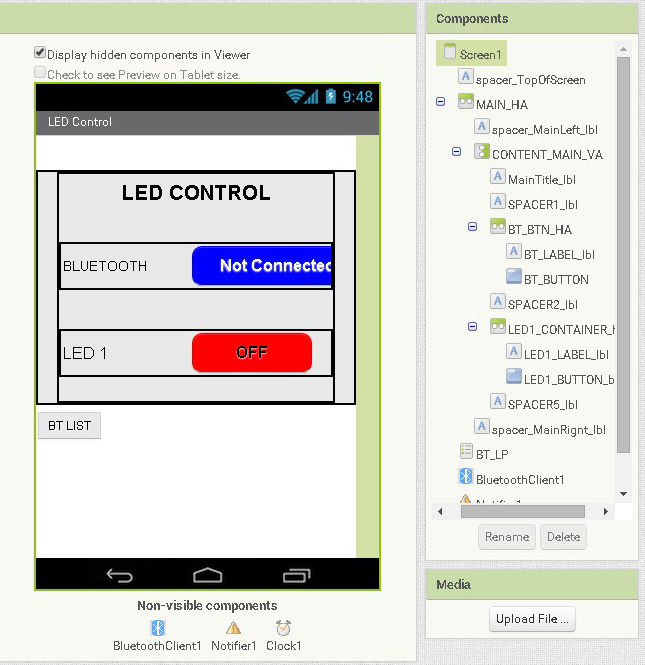
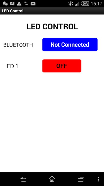
The screen is pretty simply. We have a button for activating the Bluetooth connection to the Arduino and a button to control the LED. Other elements include the Bluetooth Client, a notifier and a clock/timer.
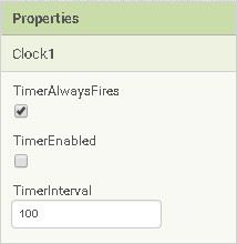 The timer (Clock1) is used to check for incoming data and is set to trigger every 100ms. This is 10 times a second and more than fast enough for this example. TimerEnabled is set to false (not ticked) which means the timer is turned off when the app starts. We turn the timer on in the blocks when the user makes a Bluetooth connection.
Commands
To help make the code as simple as possible on the Arduino we will use commands that are easy to process. The commands sent from the app use a basic code. “<[item type][number][on or off flag]>”
<L10> – turn LED 1 off
<L11> – turn LED 1 on
<L20> – turn LED 2 off
<L21> – turn LED 2 on
<L30> – turn LED 3 off
<L31> – turn LED 3 on
You will notice that all the commands are the same length. This makes things easier to code on the Arduino. Using a command type (the L for LED) allows us to add extra commands later, for example, S for slider, without the need to make big changes to the app.
Since we want to make the app easy to expand later and because AI2 has advanced text processing functions we can use slightly more complex commands when sending data from the Arduino to the app. These commands will be in the form “<[item type],[number],[on or off flag]>”. Notice the extra commas…
Commands sent from the Arduino to the app when a LED state is changed:
<L,1,0> – LED 1 has been turned off
<L,1,1> – LED 1 has been turned on
<L,2,0> – LED 2 has been turned off
<L,2,1> – LED 2 has been turned on
<L,3,0> – LED 3 has been turned off
<L,3,1> – LED 3 has been turned on
Off course we could use the same commands as used when sending data from the app to the Arduino but the extra commas allow us to easily split the command in to separate parts.
Receiving Data in the App
As already mentioned this time we will use two way communication. This means we need to have the facility to receive commands in the app. This part is probably the most complex of the new addition to the app and consists of:
– Using a timer to check for incoming data
– Adding any new data to a buffer
– Checking the buffer for a command
– Taking appropriate action when we have a command
– Remove the command from the buffer
Bluetooth communication (as with any serial communication) is not 100% bullet proof and there are things you need to watch out for.
– Only receiving part of a command
– Receiving more than one command at a time
– Receiving garbage characters
The Android App in Detail
The App Inventor 2 aia file can be downloaded at the bottom of the post.
The Blocks
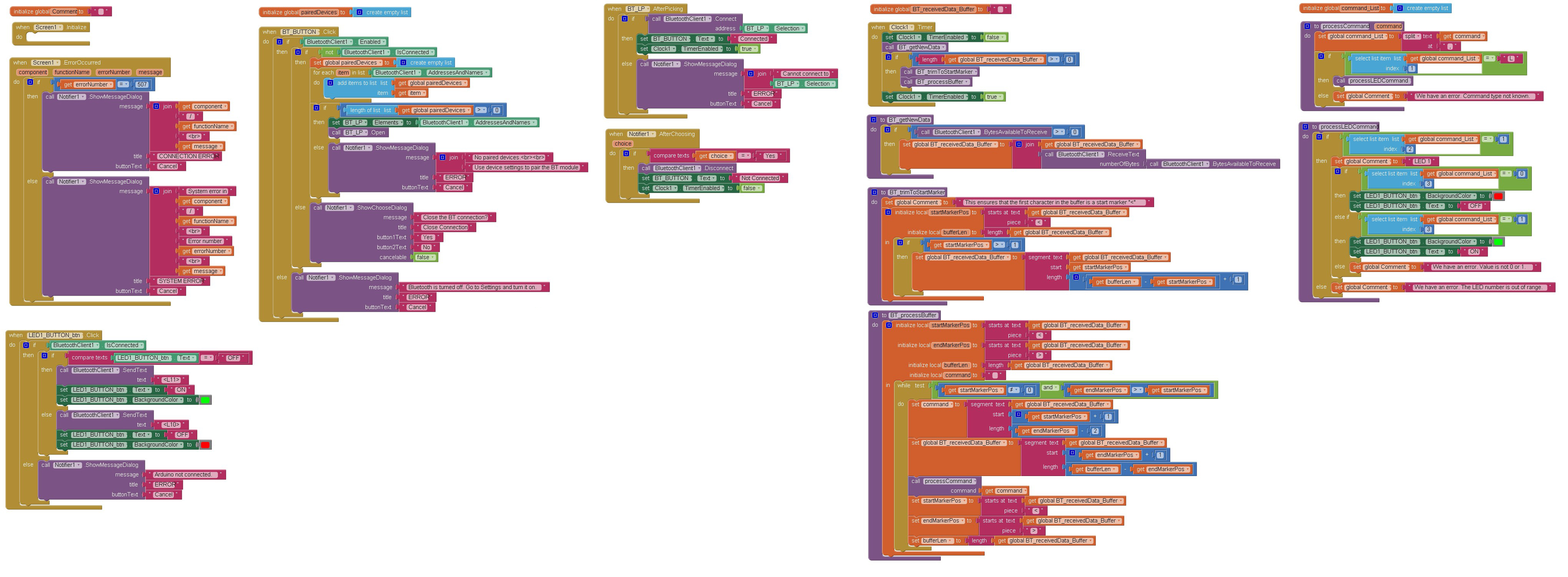
When the app first runs the screen is displayed and then it waits for user input. Before the LEDs can be controlled the user needs to connect to the Arduino. They do this by clicking the Bluetooth button and then selecting the Bluetooth module connected to the Arduino. If the user clicks one of the LED buttons before a connection is made an error message is displayed.
When the Bluetooth button is clicked the BT_BUTTON.Click block is executed.
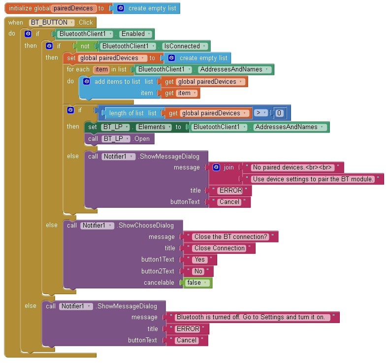
This function:
– checks that Bluetooth is turned on, and if so
– checks to see if there is NOT an active connection, if not
– the paired devices are copied to a list,
– the size of the list is checked to make sure we have at least one paired device and if there are,
– the contents of the paired devices list is copied to the ListPicker,
– the ListPicker is activated.
If Bluetooth is not turned on an error message is displayed.
If there is already an active connection the user is asked if they would like to close it.
If there are no paired devices an error message is displayed.
I use a list for the pair devices because at the time I first wrote this I could not work out how to tell how many paired devices there were from the ListPicker alone.
When BT_LP.AfterPicking
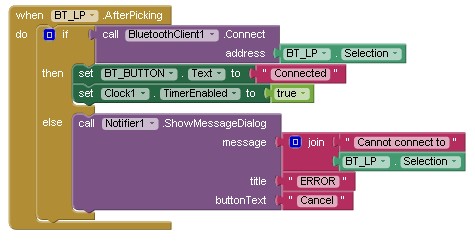
After the user selects one of the paired devices from the list picker the BT_LP.AfterPicking block is called. It is here the app tries to connect to the Arduino. If the connection is successful it changes the Bluetooth button text to Connected and starts the timer. If the connection attempt fails an error message is displayed. The timer is used to check for incoming data.
When BT_LP.AfterPicking
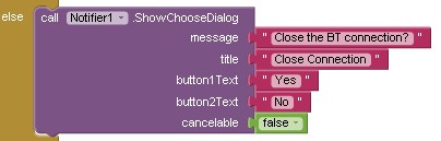
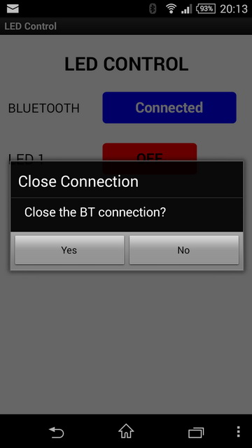
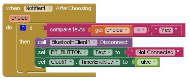
If the user clicks the Bluetooth button while there is an active connection they are asked if they would like to close the connection.
After the user selects one of the notifier options the Notifier1.AfterChoosing block is called. If the user selected “Yes” the connection is closed.
After Bluetooth has been connected and the timer has been started the app keeps checking for incoming data and also for the LED button being pressed.
LED Button
When the LED button is clicked the LED1_BUTTON_btn.Click function is called.
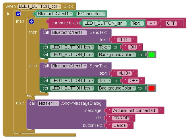
Here the app checks the current button text and if it is “OFF” it
– changes the text to “ON”,
– changes the button colour to green, and
– sends a <L11> data command to the Arduino.
If the button text is not “OFF” (IE it is “ON”) then the
– the text is changed to “OFF”,
– the button colour is changed to red, and
– a <L10> data command is sent to the Arduino.
If Bluetooth is not connected an error message is displayed.
Timer and Incoming Data
The Arduino sketch checks for incoming data every iteration of the main loop. In AI2 we do not have a main loop and we need to use a timer. Every time the timer fires a special function is called. When the timer fires the app takes a note of where it is and what it is doing, it then jumps to the timer function, performs what ever code is in the timer function and then jumps back to the previous position and carries on.
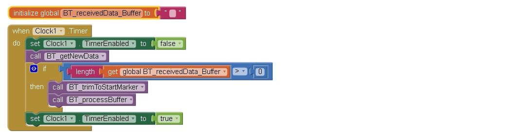
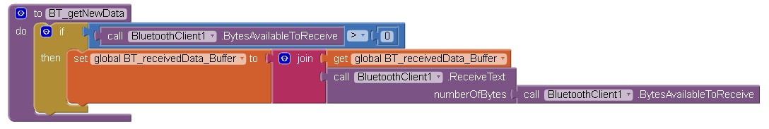
The first thing the function does is too stop the timer. This stops the timer calling the timer function before it has finished. Next the BT_getNewData function is called.
Here the app checks for new data and if there is any it adds it to the global variable BT_receivedData_Buffer.
There are no guarantees that we will receive a complete command at one time so we need to collect the incoming data and store it in a buffer. We then test the buffer to see if it contains a command.
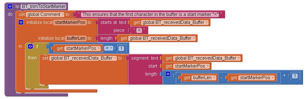
Next up is the BT_trimToStartMarker function. This trims the buffer so that the first character is a start of data marker (the “<” character). This is not really required for this example but it helps when there are more commands or the data is being sent more quickly.
After this we check for commands by calling the BT_processBuffer function.
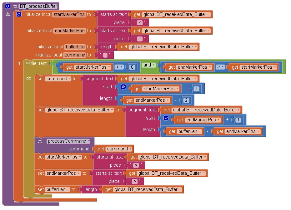
Here we check that we have both the start marker and the end marker and that they are the right way-a-round (not really required since we have trimmed the data using the BT_trimToStartMarker function).
The actual command is then extracted and sent to the processCommand function.
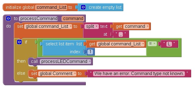
Here the command is separated in to individual elements using the split block. Here we are using the commas as the dividing points. In this example the way we are separating the command is not really required since we have fixed length commands but should we add new commands of a different length later it will come in very useful.
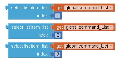
The split command puts the parts in to a list (the AI2 version of an array). The 3 parts are accessed by using the select list item block.
The processCommand function checks to see if the first property is an “L” for LED and if it is calls the processLEDCommand function.
Again this is not really required for this simple example but by doing it this way we can add extra commands easily by adding an extra condition in the processCommand function and then adding a new function to handle the new command.
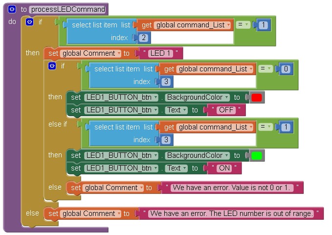
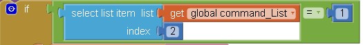
The processLEDCommand function first checks to see if the command is for LED1 with
and then it checks to see if the LED has been turned off with
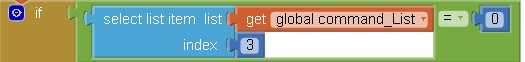
If the LED has been turned off the LED button is changed accordingly.
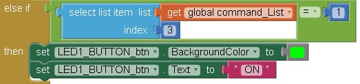
The function then checks to see if the value at uindex 3 is a 1 and if it is sets the LED button is set to show the LED is on.
If the data at index 3 is not a 0 and also not a 1 then we have an error. In the example no action is taken but you could add a warning message or display the incorrect command some way.
Arduino Circuit and Sketch
The Circuit
The circuit compromises a LED on D2 and a button switch on D5.
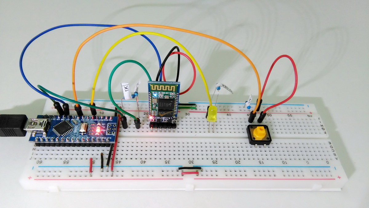
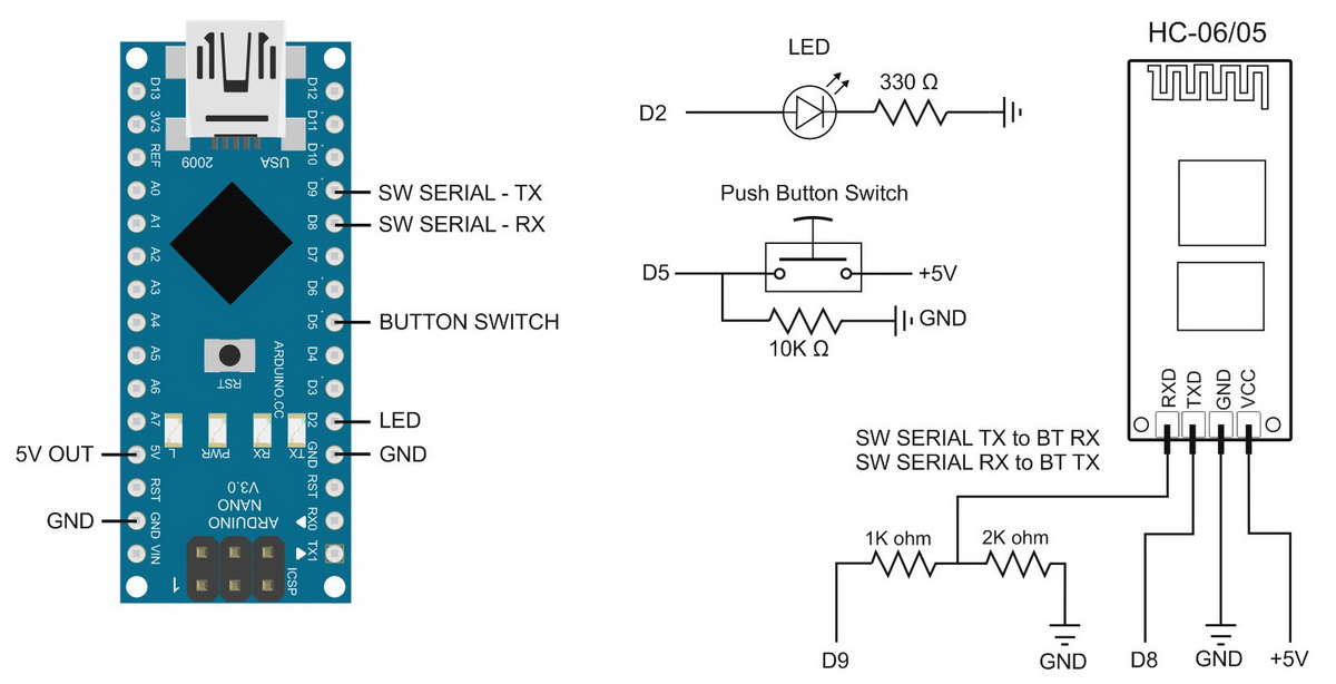
Corrected the diagram. I had the Arduino RX and TX pins swapped.
Note: The circuit shows a 330 ohm resistor on the LED where as the breadboard shows a 220 ohm resistor. The 220 ohm resistor was what I had on hand….
The Arduino Sketch
The Setup() function initialises the pins for the LED and the button switch, opens the serial channel for debugging messages and opens AltSoftSerial to the Bluetooth module.
void setup() { // Set the button switch pin for input pinMode(SWITCH1_PIN, INPUT); // Set the red LED pin for output and make it LOW pinMode(LED1_PIN, OUTPUT); digitalWrite(LED1_PIN,LOW); // open serial communication for debugging Serial.begin(9600); Serial.print("Sketch: "); Serial.println(__FILE__); Serial.print("Uploaded: "); Serial.println(__DATE__); Serial.println(" "); // open software serial connection to the Bluetooth module. BTserial.begin(9600); Serial.println("AltSoftSerial started at 9600"); newData = false; } // void setup() |
The main loop is very basic and:
– Calls the checkSwitch function which checks to see if the button switch has been pressed (closed).
– Calls recvWithStartEndMarkers() to see if there is any new data received from the Bluetooth connection.
– If new data has been received calls processCommand() which checks to see if the data is a command.
void loop() { checkSwitch(); recvWithStartEndMarkers(); // check to see if we have received any new commands if (newData) { processCommand(); } // if we have a new command do something about it } |
The checkSwitch function checks to see if the button switch has been pressed and if it has toggles the state of the LED and sends the relevant command to the Android app.
void checkSwitch() { // Simple toggle switch function with very simple debouce. boolean state1 = digitalRead(SWITCH1_PIN); delay(1); boolean state2 = digitalRead(SWITCH1_PIN); delay(1); boolean state3 = digitalRead(SWITCH1_PIN); delay(1); if ((state1 == state2) && (state1==state3)) { switch1_State = state1; if ( (switch1_State == HIGH) && (oldswitch1_State == LOW) ) { LED1_State = ! LED1_State; if ( LED1_State == HIGH) { BTserial.print("<L,1,1>" ); digitalWrite(LED1_PIN,HIGH); Serial.println("Sent - <L,1,1>"); } else { BTserial.print("<L,1,0>"); digitalWrite(LED1_PIN,LOW); Serial.println("Sent - <L,1,0>"); } } oldswitch1_State = switch1_State; } } |
The processCommand function checks the received data to see if it is a command, if it is it changes the LED and LED1_State accordingly.
void processCommand() { Serial.print("receivedChars = "); Serial.println(receivedChars); if (strcmp ("L10",receivedChars) == 0) { digitalWrite(LED1_PIN,LOW); LED1_State = LOW; Serial.println("LED1 LOW"); } else if (strcmp ("L11",receivedChars) == 0) { digitalWrite(LED1_PIN,HIGH); LED1_State = HIGH; Serial.println("LED1 HIGH"); } receivedChars[0] = '\0'; newData = false; } |
Download
Download the App Inventor 2 aia file and the Arduino sketch.
Next: 3 LEDs and 3 switches
error…
segment: start(11)+length(12) -1 exceeds text length(16)
is there a solution?
Check the commands you are sending to the app. There isn’t a lot of error checking on the data the app receives.
It looks like this error is caused by the command segment text command.
thanks you are grade ,, and iwill buy from your web bro
after i change D9 with d8 its works thanks
Do you have a programming session online??
I had the pins reversed in the diagram :-(
I have corrected the diagram. Thanks for pointing out the mistake.
Sorry, no programming guides, but there are many online.
i know there is many but you are vere good :)
Can I change the push button to capasitive touch sensor?
Sorry bad english
Yes. You would need to change the switch pin check part of the sketch.
Start with
https://playground.arduino.cc/Main/CapacitiveSensor?from=Main.CapSense
https://github.com/PaulStoffregen/CapacitiveSensor
Google arduino capacitive touch sensor will get you lots of hits.
your code works without change anything, thanks so much.
i wont to add rfid reader.
Sir I just need to take input from uC and then change label colour according to input. What changes do I need to make in your blocks as minimum as possible. As after reading your post I can sense you have used many blocks for further use or may be for some extra precautions.
Thanks for this beautiful app…
I have problem and I wish I can solve it , I am using Arduino micro and I am trying to do the above, everything went well except for the Bluetooth it did not work I installed it on my phone the app but whenever I connect to hc-06 and click on it does not trun it on the led , the switch it works. I did the voltage divider but I did not work.
is there and thing I can do so that I know where is the problem?
I think it wise to take a step back and confirm that Bluetooth communication is working. You can do this with a terminal app. Look at https://www.martyncurrey.com/arduino-and-hc-06-zs-040/
the BT module may not be the exact same one you have but the process should be the same.
Sir how can i change the code and app blocks so that when the app disconnect and connects the arduino(works continuously ) it should show the status of the leds.Because whenever the app is closed it disconnects and again when it is connected it shows the status that led is off even the led is on
hi evryone
i need make app inventor for dot matix 8*1 with persian or arabic language i cant understand how app invevtor setting for other language plese help
karim from iran
thanks 🌹🌹
How can I automaticaly turn on an LED when a specific device is connected ?