In an early version of the camControl device (before the dropController) I used an interrupter/optoisolator to detect the water drops. The plan was to detect the water drop, wait a little bit and then activate the shutter.
There are various different kinds of photo interrupter, different shapes and different sizes but all do the same job.
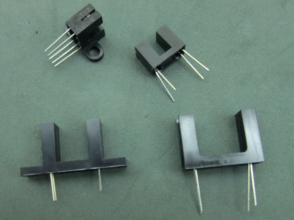
A photo interrupter has a LED at one side (normally IR) and a photo transistor at the other. When the LED in emitting light the photo transistor allows a current to flow. Remove the light and the current stops.
Photo interrupters can have 4 or 5 pins. Both types work in the same way.I purchased a range of different models and sizes. Some with 5 pins, some with 4 pins.
Connecting The Photo Interrupter
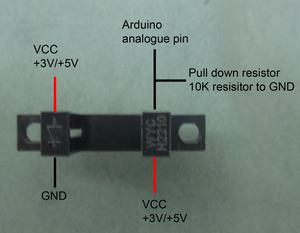
Remember to add a resistor to the LED side (not shown above). The value will be based on the voltage and the LED/interrupter used
The interrupter/optoisolator below is a Liteon LTH-301-32. This is a 5V, 20mA device. This is good for detecting water drops because it has a 15mm gap size.
To get started I created a small test circuit with just the interrupter. This allowed me to experiment and make sure things worked before I added it to the camera controller.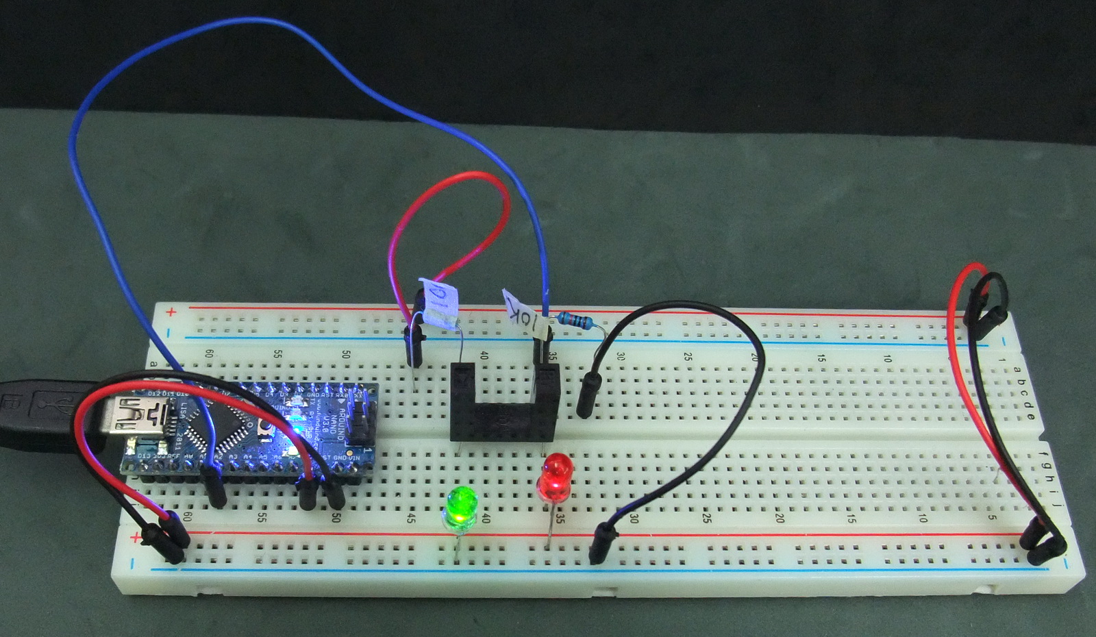
Difficult to tell from the above photo but the red LED is on. Below, with the beam broken the LED goes out.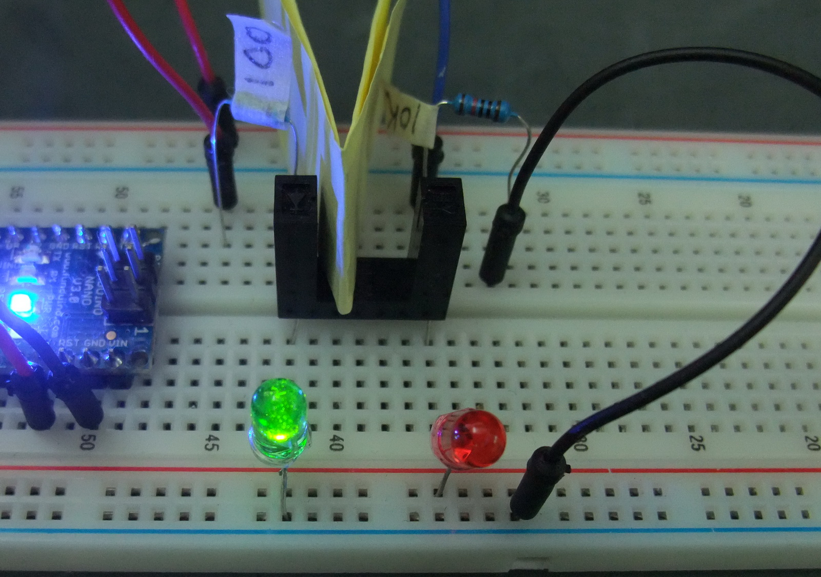
Schematic
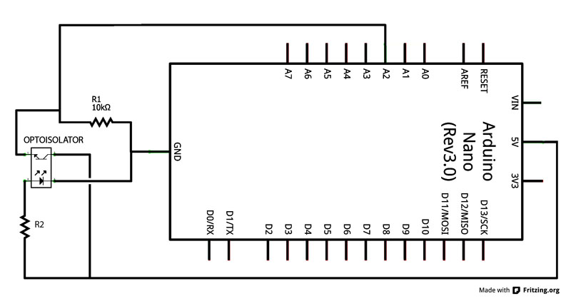
R1 10K resistor is a pull down resistor. This gives a clean reading when there is no current.
R2 depends on the photoisolator you use. Calculate the size using Ohm’s law the same as you would when using a regular LED.
Ohm’s law states that R = V / I. To use this to work out the resistor size we use the formula in the form of R = (V suplly – V forward voltage drop) / I.
Most LEDs have a forward voltage of around 2v and use about 20mA (or 0.02A) of current so when using 5V supply and a 3V photoisolator we have: R = (5-2) / 0.02A. Which equals 150 ohms. 150 ohms is the minimum and larger resistors can also be used.
Since I used the LTH-301-32 which is 5V I didn’t need a large resistor and used a 100 ohm resistor I had on hand.
The Arduino Sketch
/* Analog Read Interrupter
* -----------------------
*/

int ruptPin = 2; // select the input pin for the interrupter
int val = 0; // variable to store the value coming from the sensor

void setup()
{
    Serial.begin(9600); // set up Serial library at 9600 bps
}

void loop()
{
    val = analogRead(ruptPin); // read the value from the sensor
    Serial.println(val); // print the sensor value to the serial monitor
    delay(50);
}
Serial Monitor
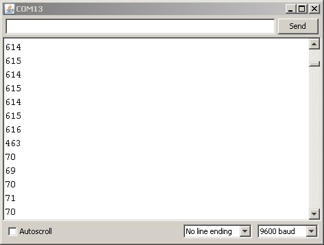
The top numbers show the value before the beam is broken. The bottom numbers are when the beam is broken.
To make use of this all you need to do is set a trigger value. Anything below 600 would do. In the Camera Controller I have a potentiometer which allows me to fine tune the trigger value while making water drops.
Water drop detector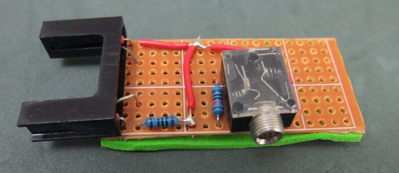
Above is the water drop detector I built. It connects to the camera control device by a standard 3.5 headphone/audio lead.
Thanks for this. Very easy to follow.
Where did you get the liteon optoisolator ?
I bought them from Taobao, a Chinese site: http://s.taobao.com/search?q=LTH-301-32
They are also available from places like Digikey http://www.digikey.hk/product-detail/en/LTH-301-32/160-1936-ND/3198349
Can I use that to detect droplets inside the tube
Yes depending on the tube and the colour of the liquid. A clear tube with clear liquid (like water) will be harder to detect and may need very fine tuning.
Can I use this with the same code?
http://media.digikey.com/pdf/Data%20Sheets/Sharp%20PDFs/GP1S73P_74P.pdf
Hi HH,
yes you can. The above code is very simple. It just reads the value from the sensor and displays it. Once you have the value you will need to determine if the beam is broken and what to do if it is.
I use the sensor to detect water drops. When a drop passes through the sensor the value goes low. When the low value is detected, the Arduino waits a short while and then triggers a camera or a flash.
hi, i want this photo interrupter for my project so from which website i can get this? plz guide me
I purchased a large bag of them from Taobao. Taobao is like a Chinese ebay.
If you google you can find many places that sell interrupters. For example the Liteon LTH-301-32 is available from:
Digi-key – http://www.digikey.com/catalog/en/partgroup/lth-301-32/32046
mouser – http://www.mouser.hk/ProductDetail/Lite-On/LTH-301-32/?qs=WxFF5lh7QM2oOLU3SLNnMA==
You can also get a lot of photo interrupters from thrown away printers. They come complete with resistors and LEDs.
plz, tell me how to photointeruppter programing sketch with arduino that can displayed into LCD 16×2, for reding the speed of motor dc(RPM).
I don’t have a finished project to share on this but you can start by looking at the following websites
http://playground.arduino.cc/Learning/Tachometer
http://www.circuitstoday.com/tachometer-using-arduino
http://duino4projects.com/arduino-rpm-counter-tachometer-code/
http://mods-n-hacks.wonderhowto.com/how-to/build-cheap-arduino-tachometer-measure-rpms-spinning-fans-and-more-0138986/
ok,
thx alot for that refrenstions Martyn .,,
Friends,
I want to connect above arduino with java program. Please help to code Serial Monitor value into java out put.
I want digitalRead mode
The photo interrupter gives an analogue value which is unlikely to work with digitalRead, usually the low value is not low enough or the high value is not high enough and digitalRead requires a faily clean digital HIGH/LOW signal.
In the example above I received a value of 615 when the beam was unbroken, this is not high enough to be read as HIGH when using digitalRead.
Look in to Shmitt Triggers; these take an analogue signal and converts it in to a digital signal and would allow you to use digitalRead.
Hello everyone. I tried to do this tutorial, but my readings are not as the one showed here. The max value I got was 136 and the min 0, but there is no big gap between them, I got values like 1 2 3 6 8 15 17 20 22 26 28 30 … 136. What I’m doing wrong?
Here’s the sensor I’m using: http://www.cromatek.com.br/pdf/opto/C860TP.pdf
Arduino UNO.
It seems the pin may be floating. Do you have a pull down resistor?
lovely…. hi everyone, please can someone help me out wit a configuration/circuit to incorporate the opto interrupter to a pi-controller for dc motor speed control with computer interface just simple components
sir ask lng sam lng po ba ito sa photo interuptor TCST1230 try kc nmn tong circuit mu but it din’t work ehh bka pag iba model d nagana?? ask lng po alam nyu po ba
HI my friend,
I have followed your code on my Arduino Yno,
this is really easy to build and use it for different project,
Thank u very much
Hello, I am Using Photo Interrupter from OMRON and I want to detect the drops. Unfortunately, I cant detect anything when i attach the sensor to a dropper. Can any one help me?
The link to sensor is: http://uk.farnell.com/omron-electronic-components/ee-sx461-p11/opto-switch-slotted/dp/1173620
And can anyone link me to a Photo Interrupter Module with a slot width of more than 15mm?
thanks in advance.
It can be difficult to get accurate readings for water drops from an interrupter. When I first started using them the trigger was very hit and miss. I had better success when I made the infrared light beam narrower by adding small pieces of thin black tube/straw.
To get a slightly wider sensor, I would normally cut the interrupter in half and use a small piece of perf board to mount the two pieces.
For times when I needed a wider sensor I used separate LEDs and photo transistors + small pieces of drinking straw.
can separate LEDS and photo transistor detect the water drop??
I have Optical slotted Switches Types OPB990t51
Five ends of wire
E) led = black and red)
S) Sensor = Green – Blue – White )
How to connect to Arduino
Take a look at the data sheet: http://www.mouser.com/ds/2/414/OPB960-990_SERIES-23547.pdf.
See the top of page 2. This gives the connections:
Lead No. Function
1 Anode
2 Cathode
3 Vcc
4 Output
5 Ground
I have a photo interrupter from a HP J6480 printer. It has three wires, Red, Black and Green. Does anyone know how to wire to an arduino uno?
What is the value of R2 in the schematic?
I used an os25b10
Hi there, i know this post is old but i wanted to know what code did you use for the water drop and what code did u use to turn on the led
The above was an experiment as part of a very early drop controller. I found the interrupter too unreliable for water drops and went a different route.
The LEDs are inline with the interrupter. Not the best example (doubles the current draw) but kept the circuit simple.
If you are interested in water drop photography have a look at http://www.dropcontroller.com.
The “water drop detector” does not identify the connections on the photo interrupter you used. As well, the colour bands on the resistors are not quite distinct enough to let the user to clearly i.d. the values of the resisters. (200 ohms / 2Kohms?)
My interrupter is a KH1A57HR — SHARP 95.
A year ago I saw a video demonstrating automated water-drop photographer, and mention was made aboard using Arduino. I realise that your item is originally quite old (as these sort of these are “old”, anyway. Nonetheless — quite interesting, and in line with a project I am building. My uses a 12v solenoid valve controlled by an Optocontroller and a relay. My problem, of course, is finding the exact moment at which to trigger the shutter.
Have a look a http://www.dropcontroller.com especially the DIY section.
I’m wondering about the schematic. I see from the code you’ve used analogRead because the change in the voltage is relatively small when the emitter voltage is connected via a resistor to ground. That may be necessary for a “dual interrupter” in the case where the two transistors share a collector, but for a single interrupter, if you get the right values according to the datasheet, you can connect the collector to 5V via a resistor and the voltage at the collector will swing between light and dark sufficiently to use digitalRead.
I noticed the same problem. You are spot on. The phototransistor is designed as an open collector output.
In the circuit above it is configured as a common emitter which causes the problem.