Breadboard Arduino / Stand Alone ATmega328P
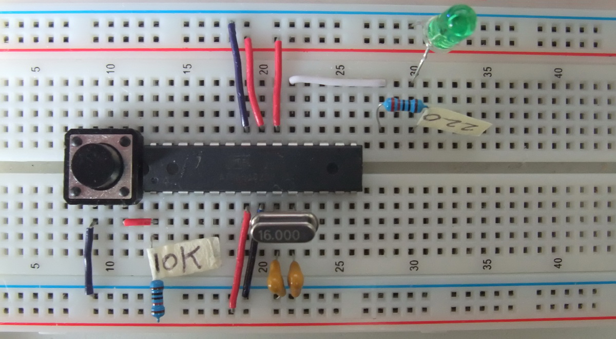
Here is my Arduino on a breadboard. There are many online guides for creating a breadboard Arduino. All are basically the same and follow the same connections. Some use pre-programmed chips, others use blank chips. My intention was to use a new blank ATmega chip (no boot loader) and use an Arduino Nano as an ISP programmer.
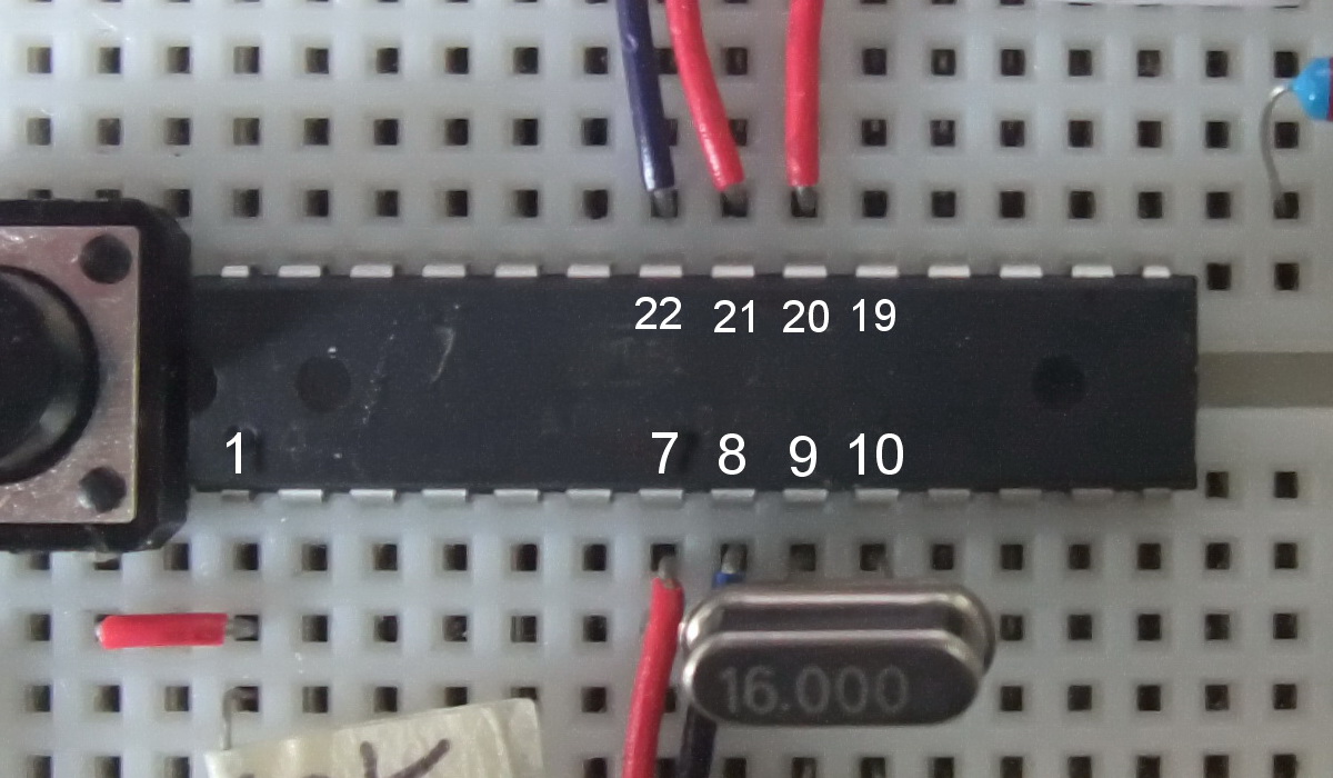
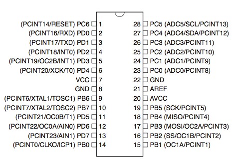
The pin numbers on the ATmega328P chip are not the same as on the Arduino. For example, pin 19 on the chip is pin 13 (the built in LED) pin on the Arduino.
Pin numbers
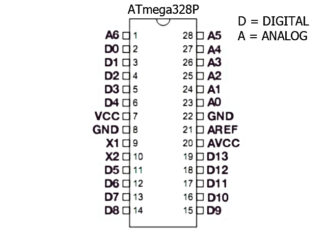
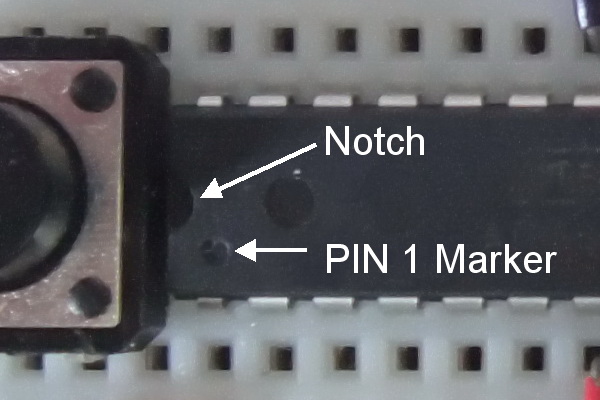
Pin 1 is indicated by a small hole.
Parts List
1 x ATMEGA 328P-PU
1 x 16 MHz crystal
1 x 220 ohm resistor
1 x 10K ohm resistor
1 x LED (Green)
2 x 22 pF capacitors (code 220)
Various jumper/breadboard wires
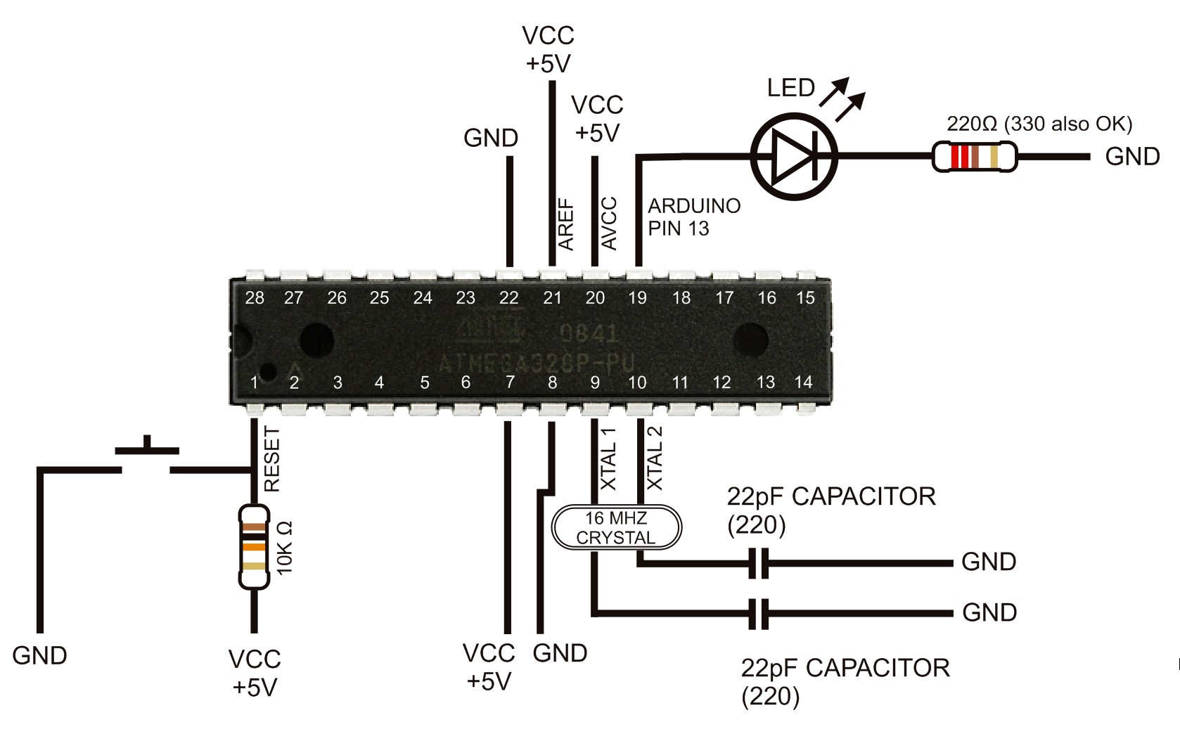
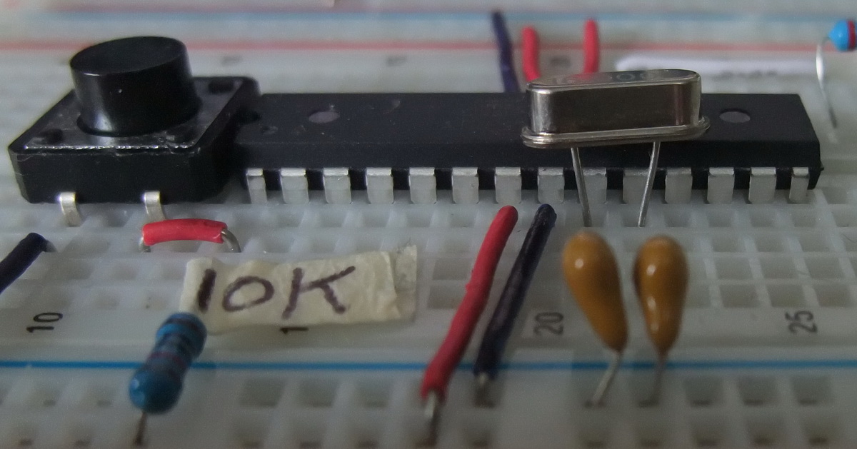
Place the Atmega 328P chip on the breadboard and add the other components and wires as per the above photo.
Pin 1 is the reset pin. When this goes low (to ground) the chip resets. To stop the ATmega 328P from continually resetting we need to keep the pin high (+5V). We do this by using a 10K ohm pull up resistor connected to the +5V supply. We then add a tactile switch between pin 1 and ground. Now, when the switch is pressed we pull pin 1 to ground which causes the chip to reset. This is just like the tactile switch on an Arduino.
Pin 7 is VCC and this goes to +5V
Pin 8 is ground so it connects to ground.
Pin 9 and 10 are for a crystal or resonator. I am using a 16MHz crystal which is the same as the Arduino. The crystal also needs a couple of 22pF capacitors. Connect the crystal to pins 9 and 10. Connect the first capacitor between pin 9 and ground, the second capacitor between pin 10 and ground.
Pin 22 is another ground. So connect to ground.
Pin 21 is AREF, the Analog reference pin for the ADC. Connect to +5V.
Pin 20 is AVCC. This is the power supply to the ADC, connect it to +5V.
Pin 19 is the Arduino D13 pin. On the Arduino this has a LED connected to it. So add a 220ohm resistor + LED between the pin and ground.
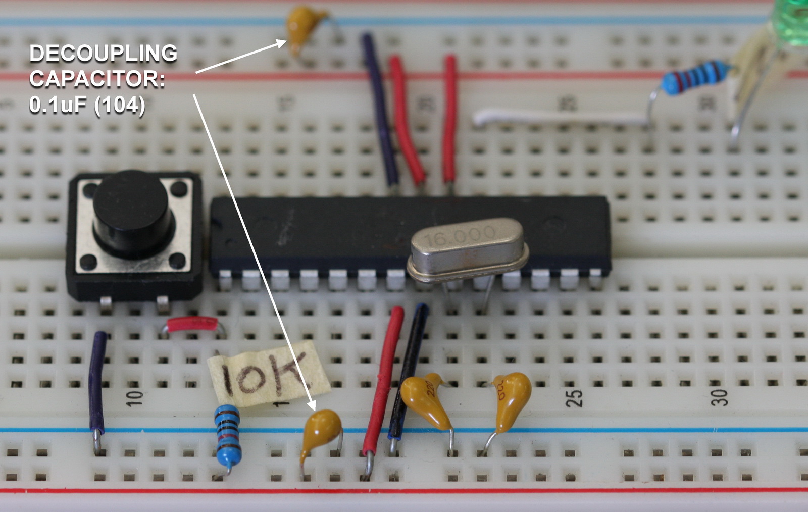
Decoupling Capacitors
If you find the chip is not operating correctly then you can add 0.1 uF decoupling capacitors to the power rails on both sides of the breadboard. Connect the capacitors across the GND and VCC lines (ideally the capacitors should be as close to the ATmega chip as possible). I have never needed to add these but I know people who have had stability issues and adding the capacitors has solved the problem.
On new Atmega328P chips, without a boot loader, the chip is set to operate using the internal clock at 1MHz. To get it to work at 16MHz we need to program special registers called fuses. The fuses hold values or flags that are used to allow you to change some of the default settings in the chip. The external 16MHz crystal will be ignored if the fuses have not been set to tell the chip to use it. Setting fuses is covered by my next post Arduino Nano as an ISP Programmer
To see if the bread board circuit worked I used a chip from an Arduino already programmed with a modified blink sketch. This is not necessary but this was my first attempt and I wanted to confirm everything worked. After confirming the circuit worked I replaced the programmed ATmega with a new blank one.
I started looking into how to use a stand alone Atmega chip with the idea of using them instead of a full Arduino in the DropControl and CamControl circuits. I then found Arduino Mini Pro clones cheaper than I can buy the components to make my own so I reverted to using full Arduinos (not only cheaper but easier to use). For the dropController project, due to the large program size, I use an Arduino without the boot loader and use my Arduino as ISP to program it.
Excellent post! Thank you.
I do lots of homebrew radio amateur projects. but digital domain was little alien to me. Wanted to know about practical arduino. This page was refered to me by a friend. Really nice write-ups. Keep it up. I find it useful.
Thanks.
Tried other guides and could not get them to work. Yours worked first time. Good to see the follow up guides explaining how to program it.
Could this be done with a 12Mhz resonator?
Your post is very useful for me.
Thanks
I have a couple questions… I do not have a crystal, and really am unable to technically buy one… don’t ask.
Also, I am using a chip that is already programmed with Arduino, so I am taking it straight off of the Arduino board and connecting it to the correct modules (lights, display etc.) What do I need to do different?
The ATmega has 2 built in oscillators, a 128kHz RC oscillator and a calibrated RC oscillator. To use the chip without an external crystal you would normally change the fuse settings letting the chip know you want to use one of the internal clocks.
This would change the frequency the chip runs at and, depending on what you are doing, may require changing the settings in the Arduino IDE or compiling the sketch at the correct frequency (normally 8MHz).
Have a look at the CKSEL section in https://www.martyncurrey.com/arduino-atmega-328p-fuse-settings/ and the data sheet, page 49 https://cdn.sparkfun.com/assets/c/a/8/e/4/Atmel-42735-8-bit-AVR-Microcontroller-ATmega328-328P_Datasheet.pdf