05.12.2015 Updated the photos.
In a previous post I showed how to make your own Arduino on a breadboard. The next step is programming it.
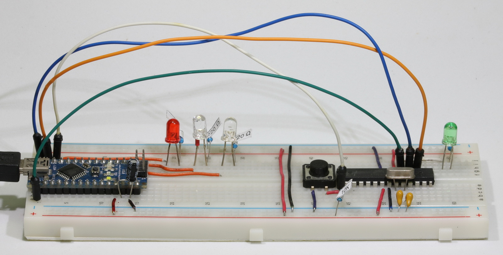
Using an Arduino Nano to program a ATmega328P chip
There are many guides online on how to use an Arduino to program a ATmega chip, two goods ones are:
Using an Arduino as an AVR ISP (In-System Programmer)
Nick Gammon’s guide
If you google “using Arduino as a programmer” you will find most of the results are for using an UNO, very few are for the Nano. One Nano guide I did find is at Lets Make Robots This explains how to set up the Nano but it does not clearly show how to program a stand alone Atmega chip.
 I assumed the Nano was the same as the Duemilanove and used the “Using an Arduino as an AVR ISP (In-System Programmer)” guide on the Arduino site. Unfortunately I couldn’t get it to work. After much google research I found that I needed to keep the reset pin on the Arduino Nano high by using a capacitor between the ground and the reset pin. I later found this is specific to certain Arduinos only.
Create the programmer
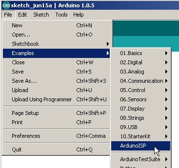
First we need to turn the Arduino Nano in to a programmer. This is done by uploading the ArduinoISP sketch. The ArduinoISP sketch is part of the Arduino software package and can be found in the examples folder.
Connect the Nano to the computer by USB as usual and load the AuduinoISP sketch in to the IDE. If you have already added a capacitor to RST & GND you need to remove it.
If you are using the Arduino 1.0 or later IDE you need to change the delay value of the heartbeat. Find
// this provides a heartbeat on pin 9, so you can tell the software is running.
uint8_t hbval=128;
int8_t hbdelta=8;
void heartbeat() {
if (hbval > 192) hbdelta = -hbdelta;
if (hbval < 32) hbdelta = -hbdelta;
hbval += hbdelta;
analogWrite(LED_HB, hbval);
delay(40);
}
and change the delay(40) to delay(20). Then compile and upload the sketch.
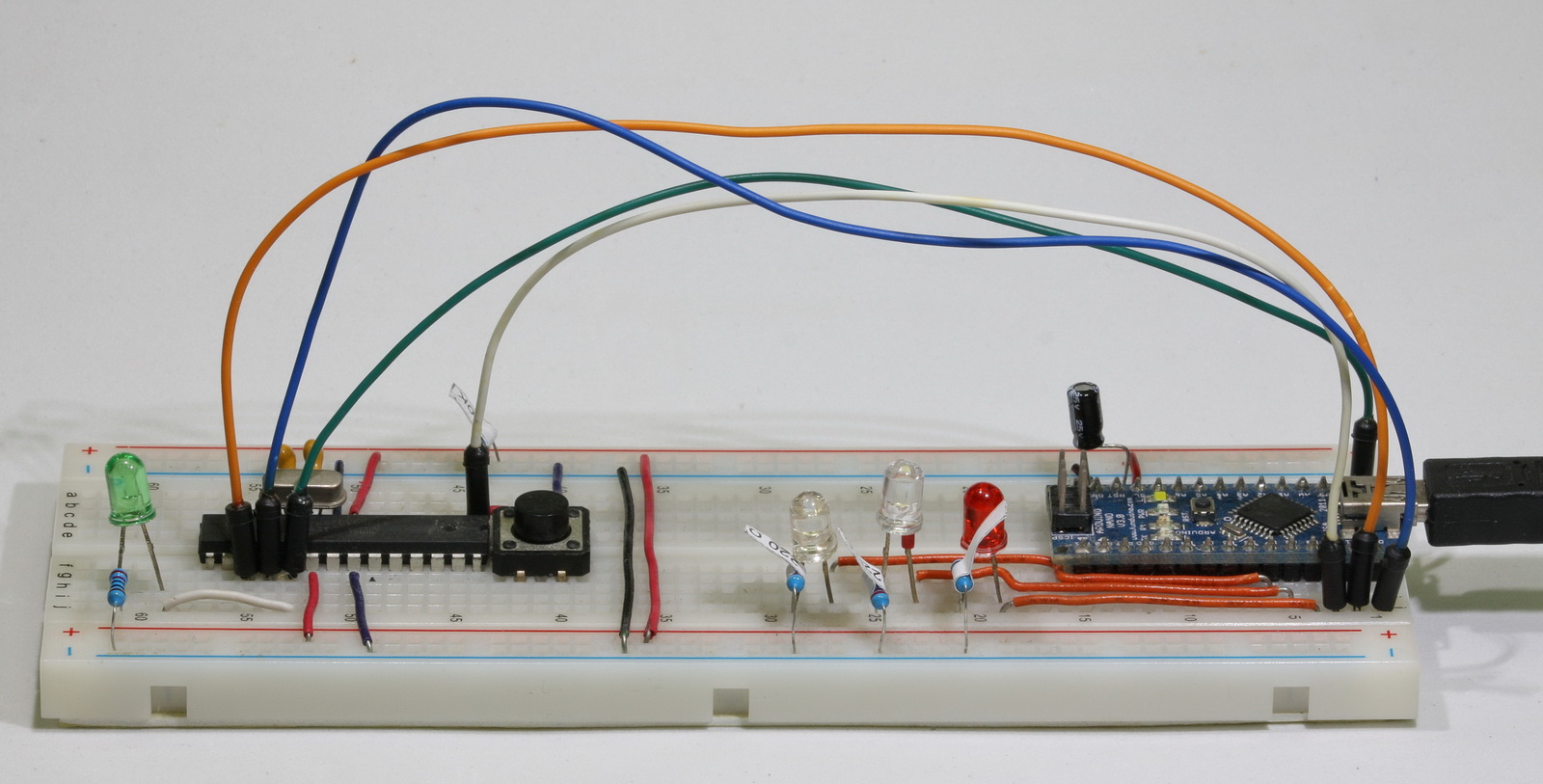
Status LEDS
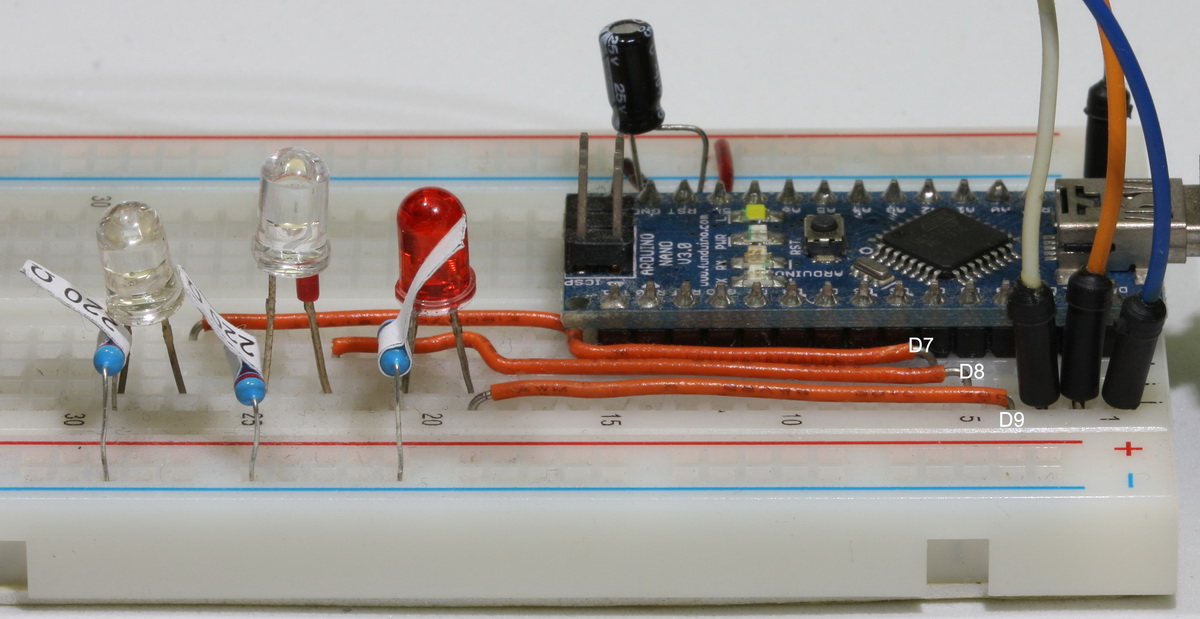
If you look at the sketch, you will see that it recommends adding status LEDs. The LEDs are optional but I prefer to have them so I can see what is happening.
// Put an LED (with resistor) on the following pins:
// 9: Heartbeat - shows the programmer is running
// 8: Error - Lights up if something goes wrong (use red if that makes sense)
// 7: Programming - In communication with the slave
I use a red LED for the heart beat and two white LEDs for error and programming.
Remove the power (USB lead) and add the resistors (220 or 330 ohm are good) and LEDS.
Reconnect the power and if everything is working you should see the LEDs quickly flicker and then the LED on pin 9 should pulse on/off.
If every is OK, disconnect the power and add the connections to the ATmega chip
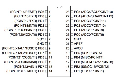
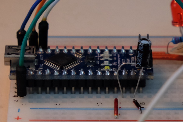
Connecting the Arduino Nano ISP to the ATmega328P chip
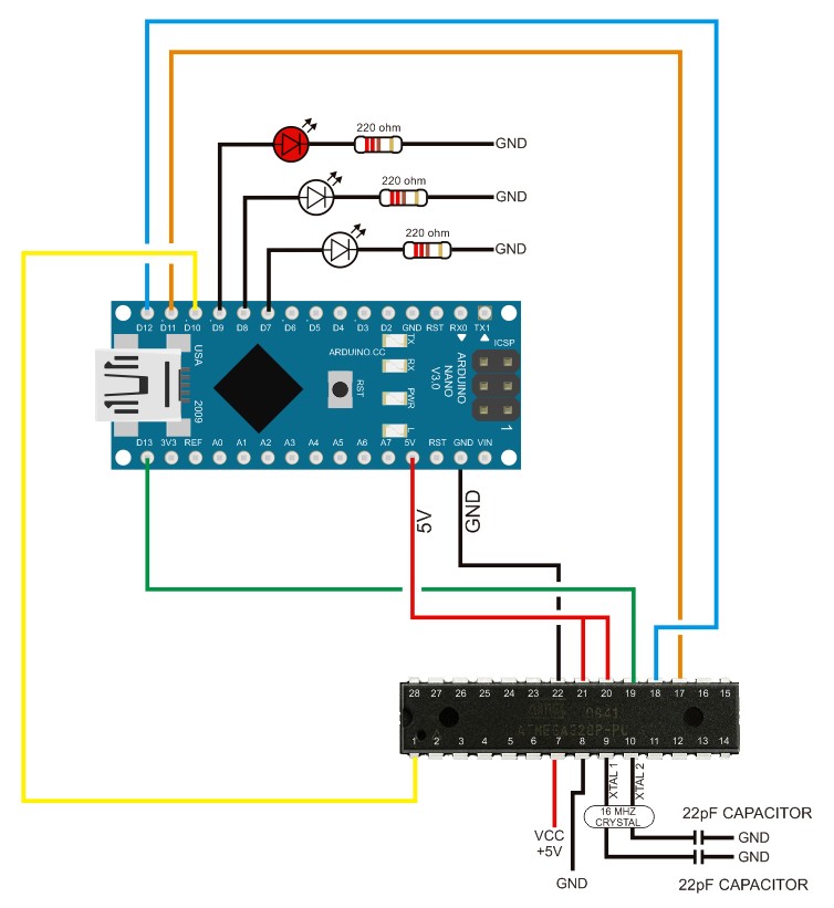
Connect the Arduino to the Atmega with wthe following connections:
Arduino D13 to ATmega pin 19 (SCK) – I used a green wire
Arduino D12 to ATmega pin 18 (MISO) – I used a blue wire
Arduino D11 to ATmega pin 17 (MOSI) – I used a orange wire
Arduino D10 to Atmega pin 1 (RESET) – I used a white wire
VCC to VCC
GND to GND
For more information on wiring the ATmega see arduino-on-a-breadboard
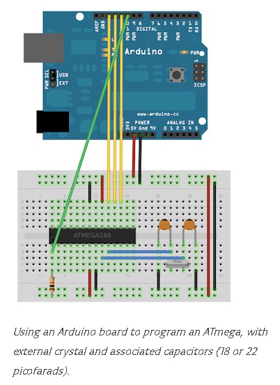
The Arduino renames the pins to make things easy for the user. The ATmega pins are shown below.
New ATmega chips are set to use the internal clock at 1MHz. We need to program the fuses so that the external 16MHz crystal is used. The easiest way to do this is to load a boot loader. This will set the fuses and we can over write the boot loader later.
Adding a new Arduino definition to the boards.txt file
When programming the ATmega chip you can select a suitable similar board in the Arduino board list but this will assume a boot loader is present and reduce the amount of program space available. We can create our own board definition that tells the Arduino IDE to use all available memory and use appropriate fuse settings. The different Arduino definitions are stored in a file called boards.txt. On Windows systems the boards.txt file is in the folder “\hardware\arduino” inside your Arduino installation folder. I normally search for it.
Rename the file to boards.BAK.
Open the boards.BAK file in a text editor, Notepad can be used, and save it in the same folder (“\hardware\arduino”) as boards.txt.
The boards.txt file contains options for various different Arduinos. These are arranged in groups and each Arduino model is separated by lines of #s.
##############################################################

uno.name=Arduino Uno
uno.upload.protocol=arduino
uno.upload.maximum_size=32256
uno.upload.speed=115200
uno.bootloader.low_fuses=0xff
uno.bootloader.high_fuses=0xde
uno.bootloader.extended_fuses=0x05
uno.bootloader.path=optiboot
uno.bootloader.file=optiboot_atmega328.hex
uno.bootloader.unlock_bits=0x3F
uno.bootloader.lock_bits=0x0F
uno.build.mcu=atmega328p
uno.build.f_cpu=16000000L
uno.build.core=arduino
uno.build.variant=standard

##############################################################
We want to create out own entry for the bread board Arduino and it is easiest to use one of the existing entries. Copy the uno entry and paste at the top of the file.
# See: http://code.google.com/p/arduino/wiki/Platforms

##############################################################

uno.name=Arduino Uno
uno.upload.protocol=arduino
uno.upload.maximum_size=32256
uno.upload.speed=115200
uno.bootloader.low_fuses=0xff
uno.bootloader.high_fuses=0xde
uno.bootloader.extended_fuses=0x05
uno.bootloader.path=optiboot
uno.bootloader.file=optiboot_atmega328.hex
uno.bootloader.unlock_bits=0x3F
uno.bootloader.lock_bits=0x0F
uno.build.mcu=atmega328p
uno.build.f_cpu=16000000L
uno.build.core=arduino
uno.build.variant=standard

##############################################################

uno.name=Arduino Uno
uno.upload.protocol=arduino
uno.upload.maximum_size=32256
uno.upload.speed=115200
uno.bootloader.low_fuses=0xff
uno.bootloader.high_fuses=0xde
uno.bootloader.extended_fuses=0x05
uno.bootloader.path=optiboot
uno.bootloader.file=optiboot_atmega328.hex
uno.bootloader.unlock_bits=0x3F
uno.bootloader.lock_bits=0x0F
uno.build.mcu=atmega328p
uno.build.f_cpu=16000000L
uno.build.core=arduino
uno.build.variant=standard
Now edit the section you have just pasted.
Change the uno at the start of each line to something else. I used “atmegasa16, short for “atmega stand alone at 16Mhz”.
Give it a new name (atmegasa16.name=)- I used “ATmega Stand Alone (Arduino as ISP)”.
Since I am not using a boot loader I can use all of the program memory so I changed atmegasa16.upload.maximum_size to 32768.
I am using the ArduinoISP so I changed atmegasa16.upload.using to arduino:arduinoisp.
Change atmegasa16.bootloader.extended_fuses=0x07 to atmegasa16.bootloader.extended_fuses=0x05. This is the standard Arduino setting. (I will cover the basics of fuse settings in another post).
You should now have:
atmegasa16.name=ATmega328P Stand Alone (Arduino as ISP)
atmegasa16.upload.protocol=stk500
atmegasa16.upload.maximum_size=32768
atmegasa16.upload.speed=115200
atmegasa16.upload.using=arduino:arduinoisp
atmegasa16.bootloader.low_fuses=0xff
atmegasa16.bootloader.high_fuses=0xdf
atmegasa16.bootloader.extended_fuses=0x05
atmegasa16.bootloader.path=optiboot
atmegasa16.bootloader.file=optiboot_atmega328.hex
atmegasa16.bootloader.unlock_bits=0x3F
atmegasa16.bootloader.lock_bits=0x0F
atmegasa16.build.mcu=atmega328p
atmegasa16.build.f_cpu=16000000L
atmegasa16.build.core=arduino
atmegasa16.build.variant=arduino:standard
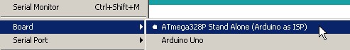
To read the new boards.txt file the Ardiono IDE must be restarted. After restarting you should have a new entry:
We should now be ready to program the ATmega chip.
Connect the Arduino Nano to the computer.
Set Fuses by Burning a Boot Loader
To make the ATmega chip use the external crystal we need to set certain fuses. An easy way to do this is burn a boot loader. When we upload a sketch later, the program memory is over written but the fuse settings are not.
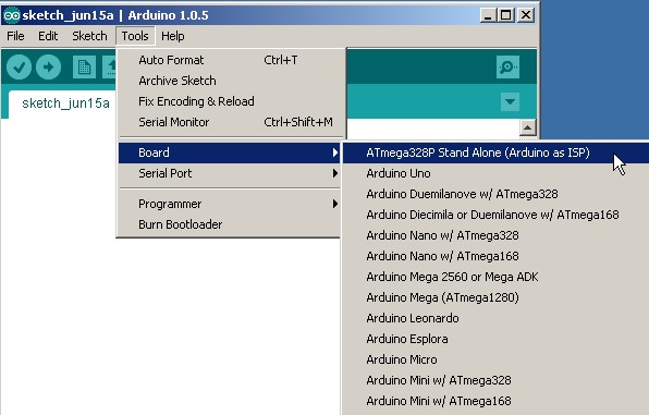
Select the Board you have just created.
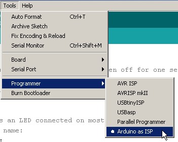
Set the Arduino as ISP as the programmer
Select Burn BootLoader.
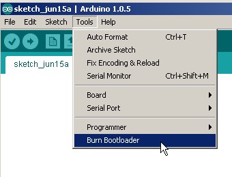
If everything is OK then the programming LED on the Nano ISP should light (pin 10) and the LED on pin19 of the ATmega328P should flicker as the boot loader is uploaded.
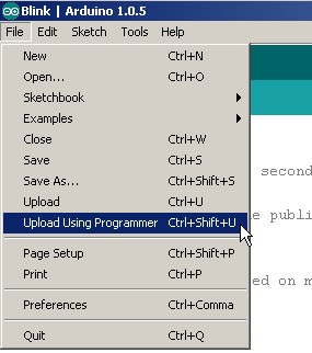
Uploading sketches to the ATmega328P
Load the example Blink sketch
Make sure the board to be programmed is the Atmega stand alone and the programmer is set to Arduino as ISP.
In the main menu select Upload Using Programmer (or press Ctrl+Shift+U) and the Blink sketch should upload.
Note that you need to use the menu option not the upload icon.
Errors
Two common errors when programming stand alone chips are
avrdude: stk500_getsync(): not in sync: resp=0x00, and
stk500_getsync(): not in sync: resp=0x15
resp=0x00 means the programmer cannot communicate with the chip. This normally means the connections are not correct (check the wires, especially VCC and ground)or you tried to upload the sketch using the Upload button in the IDE. Remember to use the File menu option
resp=0x15 is very common when the Arduino ISP is resetting. A simple solution is to add a 10uF capacitor between reset and ground on the Arduino Nano (not the Atmega chip). This keeps the reset pin high and stops the Nano resetting. Another solution is to add a 120ohm resistor between reset and +5V but I couldn’t get this to work.
I have used a couple of different Nano’s as programmers, an original that doesn’t require the capacitor, and a clone (cheap China version) that does.
if you get the following error message
avrdude: stk500_program_enable(): protocol error, expect=0x14, resp=0x50
avrdude: initialization failed, rc=-1
         Double check connections and try again, or use -F to override
         this check.

avrdude: stk500_disable(): protocol error, expect=0x14, resp=0x51
It means the ATmega is not resetting. Check the connection between Arduino pin10 and the ATmega pin 1.
Thank You for sharing!
Hi, I like your tutorial!
I want to use my nano to program a atmega16 chip. I need to load a .hex file to the chip. Is it possible to do it following this tutorial? I am just a newbie to programming btw. However, I didn´t find any tutorial on youtube, so I hope you can help me.
Thanks.
sorry, wrong reply
Thank you for your heard work.I try to edit board.text file,But window deny to save it.How can I save that file ? Can I program At mega 328p_pu with any other boad menu ?
you may need to use administrator privileges when opening the file.
Same thing over here
@sam
Thanks for sharing this –
Thanks for the detailed info! With your help I managed to upload hex data to a 328p.
I would like to share my experiences.
I wired up a nano board with a 328p and was trying to upload a .hex file to the 328p with the avrdude tool on linux. With no success at first. I got error messages with resp=0x00 and resp=0xe0 codes.
Later I found that the baudrate need to be set to 19200. The following command uploaded the code successfully: sudo avrdude -v -b 19200 -p m328p -c arduino -u -p /dev/ttyUSB0 -U flash:w:****.hex:i -U efuse:w:****:m -U hfuse:w:****:m -U lfuse:w:****:m
Note: The 10k pullup resistor connected to the pin1 of 328p to +5V is missing from the schematic drawing.
Thanks for posting this. It was the exact info I needed to fix my uploading problem, Kudos!
Easy to follow. Thanks
Sir,
u have a great tutorial. unfortunately i am having a problem while uploading the bootloader. I have cross checked the whole circuit many times but the following error is appearing again and again. Please help me.
avrdude: Expected signature for ATMEGA328P is 1E 95 0F
Double check chip, or use -F to override this check.
It sounds like you have the non P version of the chip Atmega328-PU (1E 95 14 vs Atmega328P-PU (1E 95 0F) and you may need to edit the avrdude.conf file.
Have a look at
http://forum.arduino.cc/index.php?topic=58670.0 and
http://www.instructables.com/id/Bootload-an-ATmega328/step6/ATmega328-PU-workaround/
These may help
-F is used on the command line and allows you to ignore the the ID mismatch.
For anybody else coming to this. I have just had issues with the AudionIISP reporting incorrect device signature. I have already programmed the chip and knew it was OK. After a lot of messing around I discovered it was a bad connection due to a faulty breadboard.
Really great tutorial. hooked wires and the chip to the breadboard with Nano and it worked right away without any status LEDs !!
Thank you sir for sharing your wonderful talent! more power and keep up…
I can’t believe how helpful this tutorial was. Thank you so much! I also want to note that I got the 0x14 _and_ the 0x15 errors originally. Some other tutorial said the first two 0x15 retries are normal, and to ignore them. However, I got no 0x15s when I added the 10uF cap, nor the 0x14 errors. works beautifully. Thanks again
Good day
Can you please inform me how I would achieve the following:
I have setup arduino nano as isp programmer with standalone Atmega328p-pu.
I have success with programming.
However my application of the standalone chip requires me to communicate via serial and monitor some changes via Arduino IDE Serial Monitor
Can you please inform me how I could achieve this
You need a serial to usb adaptor of some kind. The Arduino has this built in and for stand-alone avrs I find the easiest option is to use an adaptor.
This is a link to the Sparkfun one but there are lots of other (and cheaper) versions available.. https://www.sparkfun.com/products/9716
Have a look at https://www.martyncurrey.com/arduino-esp8266/. This is not for the Atmega (its for the ESP8266) but is shows how to use one of the adaptors.
Dear Martin,thanks for the wonderful detailed explanation,I am a newbie for Arduino.Can we upload the Sketches for the bootloaded AT328P in the same way.
Do you mean your AT328P already has the bootloader installed? If so, yes you can upload this way but the bootloader will be over-written/erased when uploading a new sketch.
If using this method to upload sketches you do not need a bootloader. The bootloader is used to enable communication via serial/usb and since this method does not use usb the bootloader is not required.
great, great work and explanation, thank you!
I have build it and works perfectly (with the 10uF capacitor). I added a socket for a 3 pin ceramic resonator to test the ATMega328P chip with various frequency (16 and 20 Mhz).
you are great man ,bro
i am searching this solution for months
THANK YOU
Thank you sir. Your tutorial helped me a lot!
I successfully uploaded new sketch to my smd standalone arduino chip after weeks of trying. Hooo!
Hi,
Can Arduino Nano clones be used as a programmer?
Thanks
Andrew.
yes, in the example above I uses a clone.
Hi! thanks for sharing this great tutorilal!,Im a beginner with microcontrollers.
This will work to program a 380p working with 20.000 cristal clock?
I don’t see why not but I haven’t actually tried. Give it a go and let me know if it works.
Thank you for this helpful tutorial. Unfortunately I couldn’t get it to work. While burning the bootloader I get this error:
“avrdude: Yikes! Invalid device signature.
Double check connections and try again, or use -F to override
this check.
Error while burning bootloader.”
I’m using a CH340G Arduino Nano clone, and an ATmega328P-PU bought there: http://www.ebay.com/itm/162268791626?_trksid=p2057872.m2749.l2649&ssPageName=STRK%3AMEBIDX%3AIT
My IDE version is 1.8.1.
Thank you for your help
Sebas
the most common reasons are,
– you have a different chip, not all 328Ps are the same. Use Nick Gammons chip detector to confirm. https://www.gammon.com.au/forum/?id=11633
– the chip is expecting an external clock and one is not connected or not corrected properly.
Hello sir i am using atmega 328 -pu . when i am trying to burn Bootloader its showing this message : avrdude: Yikes! Invalid device signature.
Double check connections and try again, or use -F to override
this check.
Error while burning bootloader.
CAN I PROGRAM THE BOOTLOADER ON ATMEGA 328P ON AN ARDUINO UNO BOARD ITSELF
Hello,
thanks for very good tutorial, but is it possible to burn a bootloader onto a 328p while other pins are connected to external circuitry, eg. SDA SCL pins are connected to some sensor, etc.
Thanks for your reply
It should be OK since the SDA (27) and SCL (28) are not used for programming.
You are likely to run in to issues if the sensor uses the SCK, MISO and MOSI pins though.
Hi,
thanks for sharing this great tutorial.
I have a different problem: I success to load bootloader thru. ISP, but after that, I can not successfully communicate with the ATMEGA328P thru the serial port (tx/rx…).
I check the serial cable and its look ok.
I set the fuses as: Low=ff, High=de, Efuse=ff.
Do you have any idea of the problem? Does the fuse set ok?
Thanks in advance
I don’t fully understand the issue.
Are you trying to connect via usb/serial, like a regular Arduino?
If so, you need a usb to serial adapter connected to TX (D0) and RX (D1)
How do you overwrite the bootloader after it has been burnt and run?
The boot loader is automatically over-ridden when you use a programmer rather than usb to program the Arduino or an ATMega chip.
Hi, I like your tutorial!
I want to use my nano to program a atmega16 chip. I need to load a .hex file to the chip. Is it possible to do it following this tutorial? I am just a newbie to programming btw. However, I didn´t find any tutorial on youtube, so I hope you can help me.
Thanks.
Probably easier to use one of the hex uploader programs;
http://arduinodev.com/arduino-uploader/
http://www.hobbytronics.co.uk/arduino-xloader
Thanks a million for this reply.
Hi…
can you please guide me how can i use Nano board to load Atmega8A with 4Mhz crystal.
thank you bro..
I don’t have a guide but it is very similar to the 168 and 328.
See https://www.youtube.com/watch?v=fmSNy6NAsYs for a video guide.
Will the nano programmer work programming tiny waves such as the atiny13 or a tiny’84?”
Yes it will. I don’t have any information on doing it though.
There is lots of information online and the Nano can be used the same as any other (similar) Arduino.
I would like to add my TL866CS programmer to the list. How do I know what settings need to be made for any particular programmer?
Great tutorial, worked immediately.
Looked for a universal solution for programming sketches AND boot-loader to set the fuses.
One concern: as D13 of the Arduino is connected to D19 of the ATmega chip, can you blow up the either of them as they have different output values?
Thanks so much for your explanation – great work
Tjaco
Thank you sir. Your tutorial helped me a lot!
I successfully uploaded new sketch to my Arduino nano chip after add capacitor 10uf between reset and ground.
Thanks a lot :)
Thanks for your heard work.I try to edit board.txt file ,But window deny to save it.What can I do to save that file ? Can we use any other boad to do that ?
I had to use administration mode on notepad++ to be able to save the file
Ive been using a capacitor between the atmegas reset and ground wondering why it wasnt working. Thank you for specifying to use the nano’s reset, which fixed my issue.
Hi Marty,
Please contact me.
I am looking for a arduino pro to program a prototype for a patent I am the author of .
It’s a project that can saves lives, so quite a mission to be part of !
If you or someone in your network is interested I would love to hear from you.
Please reach out
Thank you
Dee
I would be interested in working on such a project. I am a retired programmer with 35+ years of experience working with microprocessors. I have done several arduino projects. Email me if you are still looking for help.
rdgarton@email.com
Im getting same reply as you shown in last with 0x50 and 0x51 i checked reset connections again and again tried with different wires but it didn’t worked and showed same response
please help
You specify that the chip needs to use the external 16-MHz crystal in order to be programmed but can the downloaded application software use the internal oscillator?
The chip has its own internal clock and does not need to use an external crystal. However, the internal clock can only go to 8MHz and is not as reliable as an external crystal.
In the above example, the first time I program the chip it is a new chip with factory default settings. This means it is using the internal clock, not the crystal. The external crystal is connected but not used. The external crystal is not used until the fuse settings are changed to tell the chip to use the crystal.
This article is brilliant. Great job! I spend whole night trying to figure out why my nano returns errors.
Very useful. Thank you!
Hello thanks for your notes. FYI your diagram has an error: it shows a connection to pin 21 AREF of the target 328P, but you have none in the photos, and it isn’t necessary for this function.
Very nice and detailed article!
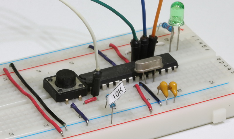
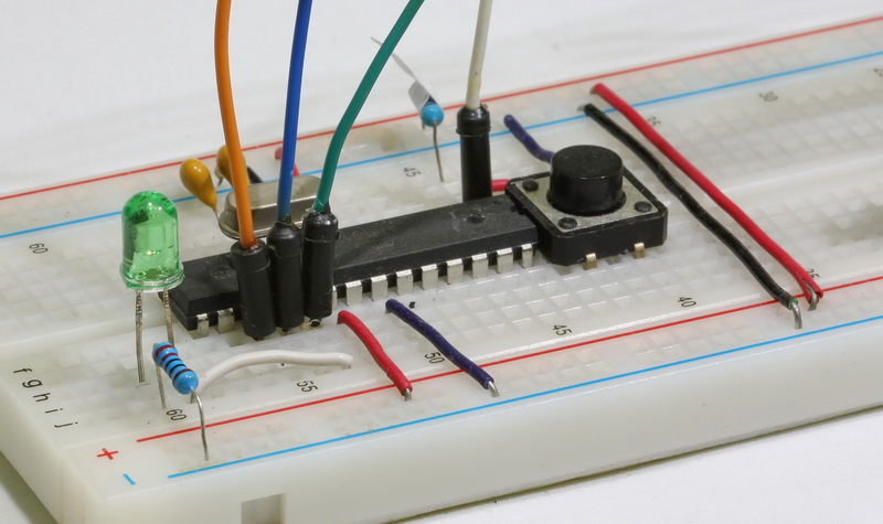
I see that you have a tactile switch on the breadboard, which is not on the circuit diagram. What is the switch for?
It is a reset button on ATmega pin 1. Pin 1 also goes to the Arduino.
Hi
I used this guide to program my naked mega. I was trying to burn the MegaCore bootloader. Very helpful. Thanks!!
However, when I tried to upload sketch directly to naked mega it says:
stk500_getsync() attempt 1 of 10: not in sync: resp=0x54
Any ideas why?
Do you have Arduino as ISP selected and are you uploading using Upload Using Programmer?
It could be the chip is not resetting just before programming.
If you have burned a bootloader you can try changing the bootloader, old to new, or new to old.
Hi Martyn
Turns out the blink sketch that I uploaded through the nano(programmer) was the cause. Your guide suggested doing that in the end.
I shouldn’t upload anything through the programmer (nano) once the bootloader burning is done. Maybe you should include this point in your guide. :) Thanks for your reply
this is the best solution
http://www.gammon.com.au/forum/?id=11635
He tenido un problema al cargar el bootloader, los pasos fueron los mismos, pero al momento de quemar el bootloader, me indica: “Error mientras se cargaba el bootloader: falta parametro de configuración ‘bootloader.tool” hay alguna idea de qué pasó aquí?
I’m getting an error which says:
***failed;
avrdude: verification error, first mismatch at byte 0x0000
0xff != 0x3f
avrdude: verification error; content mismatch
Does anyone know what it could be?
Okay, so I solved it by just selecting “Arduino Uno” as the board instead of “ATmega328P Stand Alone”, it probably was something wrong with the board.txt configuration and my version of the IDE.
Thank you!!! I had been stuck with a project for months and this helped me finish it. Amazing work.
Hi Martyn, thank you for your clear and concise article. I never used ICSP programmers with arduino sketch. I have a basic question: I would like to dedicate all the flash memory of the MCU datasheet to the sketch. I would like to use the Atmega32u4 as it has 25% more sram than the 328P although less flash is available from the internal USB. If my design is standalone, the USB would not be necessary other than to program from arduino with bootloader. How could I use this Nano programmer to program the Atmega32u4? Could I have 32768 Bytes of flash for a sketch? Would the tx, rx pins be available as rs-232 for my standalon layout? Thank you.
Hi Martyn, I’m currently testing on a pro-micro board a sketch that integrates a 128×64 pixel oled display in text mode using the u8x8 library, an SD card module that performs operations with files from command line arduino terminal, a HC-05 bluetooth module to turn on/off LEDs from movail phone, and a manual rotary encoder to dispatch orders from the oled display using external ISR. At the moment I’m at the limit (99%) of the available flash memory of 28000 bytes. With intention of taking advantage of all available flash memory space (32736 bytes) I built a programmer arduino as ICP (32u4) using a pro-micro module. Everything works fine, but I can’t find the way that the compiler recognizes additional 4096 bytes flash memory available that I have when uploading the sketch from the programmer. That does not allow me to move forward incorporating more code in new functions. Any suggestions in this regard would be greatly appreciated. Thanks.
I haven’t done any direct programming using the 32U4 so please double check the below. The first place to start should be the datasheet. https://ww1.microchip.com/downloads/en/DeviceDoc/Atmel-7766-8-bit-AVR-ATmega16U4-32U4_Datasheet.pdf
You need to change the Boot Loader Lock Bits, specifically BLB11. BLB11 controls whether or not SPM is allowed to write to the Boot Loader section. Data sheet page 329.
Since you will no longer have a boot loader area in memory, you will also need to change the AVR reset vector so that it points to 0x0000 rather than the bootloader.
Data sheet page 355 (search the data sheet for other references).
Hi Martyn,
Thanks for this work it had lots of hints to get me started. I eventualy used the code from github with the anykey locable bootloader which stops the IPS code from accidently being overwriten. I notice that your photographs and the schematic show that pin 9 is the error led but it is the heartbeat.
Best,
Peter G.
Thank you Martyn for this tutorial. I had bought a arduino nano Chinese clone at whim and was figuring out how to use it as a ISP programmer for an standalone atmega328p chip. I am probably writing this 9 years after this blog was made. I also encountered a few challenges. I am posting it here so that others trying this might find useful. I’m using ubuntu 24.04 LTS with Arduino IDE 1.8.19
1. Boards.txt file requires additional options. Arduino IDE requires additional options than ones mentioned here:
###
atmegasa16.upload.tool=avrdude
atmegasa16.bootloader.tool=avrdude
###
In my PC, boards.txt file is in the following path:
/usr/share/arduino/hardware/arduino/avr/
2. Bootloader path
Also, inspite of atmegasa16.bootloader.path being set as optiboot, I still needed to specify the full path.
###
atmegasa16.bootloader.path=optiboot
atmegasa16.bootloader.file=optiboot/optiboot_atmega328.hex
###
In my PC, the optiboot is in the following path:
/usr/share/arduino/hardware/arduino/avr/bootloaders/optiboot
3. Makefile had a mismatch with the optiboot’s size. More on that here:
https://forum.arduino.cc/t/optiboot-issue-avrdude-error-address-0x8010-out-of-range/863387
Hope this helps.