Part of programming stand-alone ATmega chips is setting the fuse bytes, these are special settings that can be used to change how the ATmega chips operate.
Some of the things you can do by changing the value of the fuses include;
- select different clock sources and change how fast the chip runs,
- set the minimum voltage required before the chip works.
- set whether or not a boot loader is used,
- set how much memory is allocated to the boot loader,
- disable reset.
- disable serial programming
- stop eeprom data being erased when uploading a new sketch.
There are many articles online but I could not find a single source that brought all the information together and fully explain what the fuses actually do.
It is important to remember that some of the fuse bits can be used to lock certain aspects of the chip and can potentially brick it (make it unusable). However, with a bit of care it is fairly straight forward to understand and use the fuse settings.
Disclaimer, I am relatively new to programming fuses and these are notes I wrote to help me remember things. The information is based on the data sheet for the ATmega chip, internet searches, and questions I asked on forums (especially the Arduino forum).
There are 3 bytes in total:
- low byte fuse,
- high byte fuse,
- extended fuse
There is also a forth byte that is used to program the lock bits. Lock bits are not covered by this article.
Each byte is 8 bits and each bit is a separate setting or flag. When we talk about setting/not setting, programmed/not programmed fuses we are actually using binary. 1 means not set/not programmed and a 0 (zero) means set/programmed.
When programming the fuses you can use binary notation or more commonly hexadecimal notation. For 8 bits (1 byte) we can use B11111111 or 0xFF. Both are the same value.
Note: For all fuses, a value of 1 means not set and a value of 0(zero) means set.
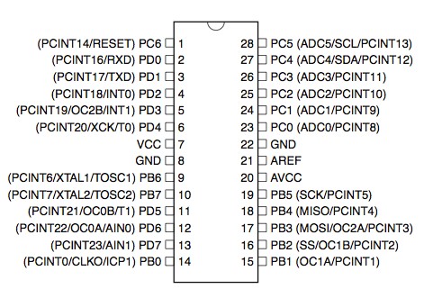
ATmega 328P 28 PDIP diagram
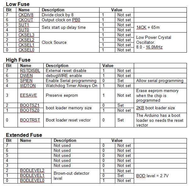
Low Byte Fuses
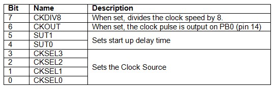
The low byte fuse deals with the clock source, how fast the chip will run, and how long it waits at startup.
The ATmega chips can be run at different speeds or frequencies and the frequency is determined by the clock source that is used. The clock source is set by using the CKSEL fuse bits.
CKSEL (Clock Sources / Clock Selection)
The clock signal can come from an internal oscillator, an external crystal/resonator, or an external signal. Arduinos normally use an external 16MHz crystal.
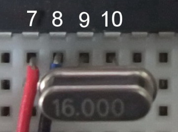
Here is a 16 MHz crystal used on a bread board Arduino connected to XTAL1 and XTAL2. The ATmega chip has to be told to use the external crystal and this is done by setting the CKSEL bits. A common mistake is to have the crystal correctly connected in the circuit but forget to tell the chip to use it.
The different options for CKSEL are:
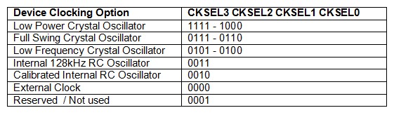
Arduinos normally use a low power crystal oscillator.
The ATmega has 2 built in oscillators, a 128kHz RC oscillator and a calibrated RC oscillator.
The external clock option allows the chip to use an external square wave clock signal. This is used when you have a circuit with its own clock that you want to sync the ATmega with or if you want to use a separate clock chip. The external clock signal needs to be connected to the CLOCK-IN pin
Crystal Oscillator Options
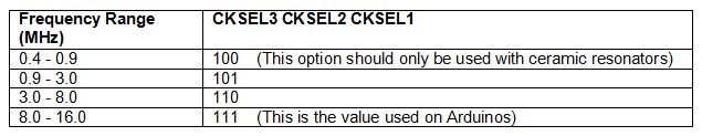
CKSEL3=1 CKSEL2=1 CKSEL1=1 CKSEL0=1 selects a crystal any where from 8MHz to 16MHz and is the normal setting for Arduinos.
If you want to use a slower crystal, for example 6MHz, then you would use CKSEL3=1 CKSEL2=1 CKSEL1=0 CKSEL0=1 (the 3.0 to 8.0 range).
To use the internal RC oscillator at 8MHz, the settings are CKSEL3=0 CKSEL2=0 CKSEL1=1 CKSEL0=0
SUT1/SUT0 (Start Up Time)
Crystals and oscillators require sufficient voltage to operate correctly. When you start the ATmega chip it can take a brief period of time for the voltage to get to its maximum value. While the voltage is rising the clock source may not be working at the correct speed or frequency. To allow the clock to stabilise a startup delay can be set.
CKSEL0 is used together with SUT1 and SUT0 to set the start up delay time.
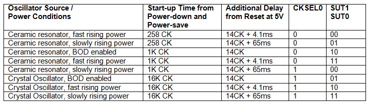
BOD is Brown Out Detection and discussed later.
The Arduino uses the maximum startup delay of 14CK + 65ms (CKSEL0=1, SUT1=1, SUT0=1) which are also the default settings for new ATmega 328/328P chips.
CHDIV8 (Clock Divide)
ATmega 328/328P chips have a built in RC oscillator which has a 8.0MHz frequency. New chips are shipped with this set as the clock source and the CKDIV8 fuse active, resulting in a 1.0MHz system clock. The startup time is set to maximum and time-out period enabled. (CKSEL = “0010”, SUT = “10”, CKDIV8 = “0”). This setting is used so that all users can make their desired clock source setting using any available programming interface.
CKDIV8 should be used if the selected clock source has a higher frequency than the maximum frequency of the ATmega chip.
The ATmega chips can be used at very low voltages, however, the lower the voltage the slower they need to work at. The CHDIV8 can be used to set a slow clock speed to match a low voltage.
CKOUT (Clock Out)
The clock signal can be routed to PB0. This is useful if you need the clock signal to drive other circuits. This works for all clock sources and the default setting for new chips is CKOUT=1 (not set).
High Byte Fuses
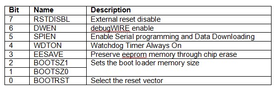
The high byte fuse has several different settings. The ones of normal interest (to me as a hobbyist at least) are the watchdog timer, preserving or erasing eeprom and the boot loader attribute settings.
RSTDISBL (External reset disable)
PC6 is a reset pin, hold it low (to ground) and the chip will reset. This is how the switch on the Arduino works. When you press the reset button it connects PC6 to ground and resets the chip.
PC6 can also be used as a regular IO pin but this means disabling the reset function which in turns means the chip can no longer be inline programmed (in line programming requires a reset). This is one of the options it is better not to change.
I imagine RSTDISBL is implemented for security reasons to stop the chip being reprogrammed or the firmware being downloaded.
When RSTDISBL is programmed the start up time (SUT1 SUT0) is increased to 14CK + 4.1ms to ensure the programming mode can be entered.
By default, the setting is RSTDISBL=1 (not set).
DWEN (debugWIRE enable)
ATmega chips have built in debugging tools which are by default turned off. The DWEN fuse is used to turn them on.
DWEN uses the same pin as reset (PC6) and when DWEN is enabled (and the lock bits are not set) the reset pin becomes a communication pin and normal reset no longer works. For example, if you enable DWEN on an Arduino the reset button no longer works.
To use the on-chip debugging you need a compatible programmer such as the AVR Dragon. Since I have never used AVR studio and do not have a suitable programmer I have never used and do not know how to use debugging. If you would like to know more then there is a good article at http://www.hilltop-cottage.info/blogs/adam/debugging-arduino-using-debugwire-atmel-studio-and-an-avr-dragon/ to get you started.
This is one of the fuses you should take care with. If you enable DWEN and also enable the lock bits you can no longer program the chip in the normal way.
If you are just starting then leave DWEN to not set. After all, reset is very useful.
SPIEN (Enable Serial programming and Data Downloading)
ATmega chips can be programmed using serial programming. Serial programming is used for on board programming using a serial protocol via an ISP (inline serial programmer) or UART (universal asynchronous receiver/transmitter).
The normal method of programming the ATmega chips is via the SPI interface using the SCK (clock), MOSI (input) and MISO (output) pins. If you disable serial programming then you can no longer use the SPI to program the chip. You can also disable serial programming using the lock bits.
For normal use and development leave SPIEN enabled, however, if you have a device that is final and no further programming is required then you can use this option to stop people accessing the chip through serial communication.
The default setting is SPIEN enabled, SPIEN=0.
The RSTDISBL, SPIEN and DWEN fuses have the potential to brick the ATmega chip, or at least make the chip very very difficult to use again. For general use, and especially if you are just starting out with programming stand-alone chips, you should not change these fuse settings. You should also double check that you are not changing them when you re-write the other fuse settings.
WDTON (Watchdog Timer Always On)
The watchdog is basically a timer that will cause the chip to reset if it does not receive an OK signal at specific times.
This can be useful when you have unstable code or have a system that must not be allowed to permanently lock up.
When the watchdog timer is enabled, should a sketch crash or freeze then the timer will time out and reset the chip causing a restart similar to pressing the reset button an a running Arduino.
The Watchdog Timer can be activated in software so the fuse settings doesn’t really need to be used. By default, the watchdog timer is off, WDTON=1.
There is a nice mini guide on the Watchdog timer by za_nic on the Arduino forum at ttp://forum.arduino.cc/index.php/topic,63651.0.html
Paul Martinsen has a guide on how to use the watchdog timer to detect lockups at http://www.megunolink.com/how-to-detect-lockups-using-the-arduino-watchdog/
EESAVE (Preserve EEPROM memory)
When the ATmega chip is programmed the memory is erased just before the new code is uploaded. Under normal circumstances the eeprom memory is erased as well as the program memory. The EESAVE fuse can be used to tell the chip not to erase the eeprom. This is useful when you want to upgrade code but keep user settings that are stored in eeprom.
The default value is EESAVE=1, not set and eeprom memory is erased during the chip erase cycle when programming.
I have got into the habit of setting this fuse; eeprom has a limited life cycle so the less you write to it the better. Erasing the eeprom has no effect on uploading new code and the majority of my projects don’t use the eeprom memory so not erasing it is not a problem. The dropController stores settings and drop times in eeprom and so I set EESAVE to preserve the data when I upload new versions of the code.
BOOTSZ1 & BOOTSZ0 (Boot loader Size)
The ATmega chips have the ability to use a boot loader, this is a small program that runs when the chip is first started or when it is reset. Boot loaders are normally used to initialize the device and check for external communication. The Arduino uses a boot loader to talk to a connected computer to see if there is a new program to be uploaded. This is the reason the Arduino resets when you upload new code, the reset runs the boot loader, the boot loader checks to see if you have new code.
The boot loader is stored in program memory, the same memory used for the user application and since the boot loader can be different sizes you can tell the ATmega chip how much space to reserve. The regular (older) Arduino boot loader is 2 kilobytes (KB) but the newer Optiboot (used on the UNO) is only 0.5KB (512 bytes). If using Optiboot and setting the boot loader size accordingly you gain an extra 1.5KB for your own program. 1.5KB can be a lot of space, running out of program space is why I started programming stand alone ATmega chips in the first place. The code for the dropController became too large for the regular Arduino so I removed the boot loader.
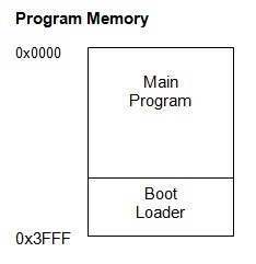
The boot loader is stored at the top of the program memory
If you have a boot loader then BOOTSZ has to be used in conjunction with BOOTRST. BOOTRST tells the ATmega chip the memory address where the boot loader starts. If BOOTRST is not set then the user application can use the whole of the memory regardless of the BOOTSZ settings.
Boot Size Configuration for the 328/328P
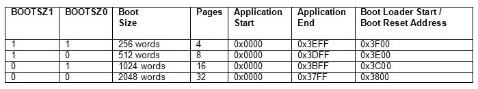
Note that the above sizes are in words (a word is 2 bytes) and 256 words is 512 bytes.
The default for new chips is BOOTSZ1=0 BOOTSZ0=0 which means they have 4KB reserved for a boot loader.
BOOTRST Select reset vector
ATmega chips can use a boot loader, this is a small program that runs when the chip is reset. If you have a boot loader then you need to inform the MCU and this is done by using the BOOTRST fuse setting. When the BOOTRST Fuse is set, on reset the device will jump to the Boot Loader address. If not set, the chip will jump to the program start address at 0x0000.
The default value is BOOTRST = 1 (not set).
If BOOTRST is not set (no boot loader) then the BOOTSZ fuses are ignored.
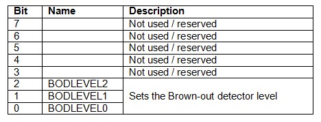
Extended Fuse Bits
The extended fuses are only used to set the brown-out detection level (BOD).
The ATmega chips can become unstable or unreliable when used with insufficient voltage. For example, the 328/328P can run safely at 16MHz if it has at least 4V. Anything below 4V means the chip is likely to misbehave. This would be a problem if the device were being used with sensors to take measurements or relied on accurate timings.
To ensure the chip has sufficient input voltage a minimum voltage level can be set. If the voltage falls below this level then the chip will reset itself. This is called the brown-out detector level. Basically, if the supplied voltage is below the BOD the chip keeps reset low.
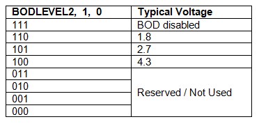
The default values for new chips are; BODLEVEL2=1 (not set), BODLEVEL1=1 (not set), BODLEVEL0=1 (not set).
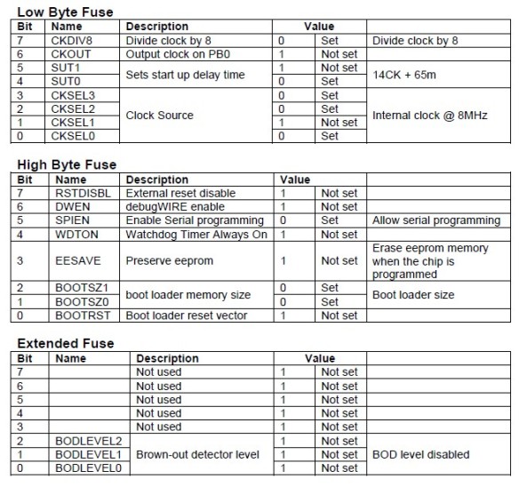
Default Fuse Settings
New ATmega 328P Chip.
New 328/328P chips generally have the following fuse settings:
Low fuse = 0x62 (B01100010)
High fuse = 0xD9 (B11011001)
Extended fuse = 0xFF (B11111111)
Arduino Duemilanove or Nano w/ ATmega328 Default Fuse Settings
Low fuse = 0xFF (B11111111)
High fuse = 0xDA (B11011110)
Extended fuse = 0x05 (B00000101)
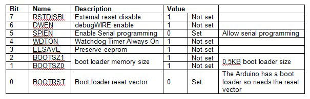
Optiboot Boot Loader
If you load the Optiboot boot loader then the high byte fuse should be set as 0xDE (B11011110). The only difference is the space allocated to the boot loader.
For a comprehensive list of the default fuse settings for the various Arduinos have a look at Coding with Cody’s Arduino Default Fuse Settings page.
Lock Bits
Lock bits can be used to restrict read/write access to the program memory. The boot section and the application section have their own lock bits and access for each area can be controlled separately.
You can brick the ATmega chip if you enable the lock bits and you should not change them.
I will try to cover lock bits in more detail in a later post.
Actually Programming The Fuses
To program stand-alone ATmega chips I used an Arduino Nano as programmer, see Arduino Nano as an ISP Programmer and found the easiest way to set the fuses was to burn a boot loader (the fuses are set as part of the process). The boot loader can then be written over later when you upload a sketch. By editing the boards.txt file in the Arduino installation folder you can use any values you desire for the fuses.
Here is the entry I added to boards.txt for use with bread board Arduinos. This has the low byte fuse at 0xFF, the hight byte fuse at 0xDF, the extended fuse at 0x05, and uses the Optiboot boot loader. The values for the lock bits were copied from the Arduino Uno entry.
atmegasa16.name=ATmega328P Stand Alone (Arduino as ISP)
atmegasa16.upload.protocol=stk500
atmegasa16.upload.maximum_size=32768
atmegasa16.upload.speed=115200
atmegasa16.upload.using=arduino:arduinoisp
atmegasa16.bootloader.low_fuses=0xff
atmegasa16.bootloader.high_fuses=0xdf
atmegasa16.bootloader.extended_fuses=0x05
atmegasa16.bootloader.path=optiboot
atmegasa16.bootloader.file=optiboot_atmega328.hex
atmegasa16.bootloader.unlock_bits=0x3F
atmegasa16.bootloader.lock_bits=0x0F
atmegasa16.build.mcu=atmega328p
atmegasa16.build.f_cpu=16000000L
atmegasa16.build.core=arduino
atmegasa16.build.variant=arduino:standard
Useful links
Nick Gammon’s site has a lot of really good information about building your own Arduino and uploading boot loaders:
How to make an Arduino-compatible minimal board (similar to mine).
Solving problems with uploading programs to your Arduino
ATmega bootloader programmer.
My own Arduino on a breadboard explains how to set up a stand-alone ATmega chip and Using an Arduino Nano to program a ATmega328P chip explains how to use an Arduino as an ISP programmer.
The ATmega 328P data sheet can be down loaded from the Microchip website.
http://eleccelerator.com and http://www.engbedded.com both have a fuse calculator where you select what options you want and the page gives you the fuse settings to use. I prefer not to use the calculators as I think it may be easy to make mistakes but this is my personal opinion only.
NIck Gammon also has a useful sketch that detects ATmega chip types. The sketch can be found at http://www.gammon.com.au/forum/?id=11633. The sketch displays the fuse settings, the lock bits and gives information about the boot loader if one is present. I found this sketch very useful when I first started programming chips directly.
Hello,
I am trying to change the atmega328p’s clock source as an external clock signal coming from the function/signal generator.
I will use the avrdude to change the fuse bits and I have an AvrmkII ISP,
My question is do i need to plug the atmega328p out of the Arduino board and connect on a bredboard in order to feed an external clock source ? or connecting the function generator to XTAL1 ( pin9) on Arduino board works as well ?
I’d appreciate for any help. Thank you very much
Better to put the 328P on a breadboard. The external clock signal goes to PB6/XTAL1 (pin 9) which on an Arduino has the crystal connected.
Very helpful. Thank you for posting it all. It has enabled me to progress my project, and write a boards.txt entry to put the optiboot loader onto my arduino nano.
Just one tiny error I spotted: in the Optiboot boot loader table, showing the fuse settings, you correctly have both of the BOOTSZ bits set to 1, but you say BOOTSZ1 is “set”, but BOOTSZ2 is “not set”.
Phil
Thanks for pointing out the typo. I have corrected the Opitboot chart.
A really very very helpful informative suggestion. Thank you for your effort. Keep it up. Be always well n happy,,,,
Hello,
Just wanted to point out the BOOTRST section:
“The default value is BOOTRST = 1 (not set).”
Should that not be a 0 instead of a 1? One means that the bootrst is set, isn’t it?
Great tutorial!
BOOTRST = 1 (NOT set)
BOOTRST=1 is set, but not Programmed
SPIEN (Enable Serial programming and Data Downloading).
if SPIEN=1, then it is not possible to upload program via SPI.
Is any problem if we are using arduino ethernet shield?
Sorry, I don’t know. Although I have an Ethernet shield I have never used it.
If you disable SPIEN then you can no longer program the Arduino/ATmega chip in the usual way, either by ISP or by USB.
Default Fuse Settings
New ATmega 328P Chip.
New 328/328P chips generally have the following fuse settings:
High fuse = 0xDB (B11011011) wrong it is D9 (2048 not 1024)
Also you High Byte Fuse chart in incorrect re D9
HI,
you are correct and I have updated the post.
Hey,
small mistake in your good discription !
“”The ATmega has 2 built in oscillators, a 128MHz RC oscillator and a calibrated RC oscillator.””
Sure, 128 Mhz – !!!!!
thanks
Fixed.
I blame my keyboard. The keys keep moving….
The Atmega328 Arduino also worked with the fuse settings you see.
Thank you
When I add the code you provided to my boards.txt, do I add it to the bottom of the code that is already there? Do I change anything else? Will this change show an additional “board” being available when I choose what programmer to use? ( I read another article that stated a “new” option should appear after modifying boards.txt) Thank you for taking some extra time explaining the material, many other authors forget what it is like to not understand how to work with bootloaders and how to change things to be able use the internal clock and not use the external crystal/caps.
Top, bottom, middle. Really doesn’t matter as long as all the relevant parts are together. I generally add to the top so it is easy to find.
A new entry will be available – see the https://www.martyncurrey.com/arduino-nano-as-an-isp-programmer/ post. This goes through editing the board.txt file.
Nice page, well done. However, you write:
Arduino Duemilanove or Nano w/ ATmega328 Default Fuse Settings
…
High fuse = 0xDA (B11011110)
Your hex & binary values are not the same…
From the file arduino-1.8.6\hardware\arduino\avr\boards.txt:
uno.bootloader.tool=avrdude
uno.bootloader.low_fuses=0xFF
uno.bootloader.high_fuses=0xDE
uno.bootloader.extended_fuses=0xFD
uno.bootloader.unlock_bits=0x3F
uno.bootloader.lock_bits=0x0F
uno.bootloader.file=optiboot/optiboot_atmega328.hex
Thank you Martyn for a detailed explanation on Atmega328p fuses. It was helpful.
Martyn,
First, thank you so much for taking the time to make this tutorial and also the ones you’ve done on Bluetooth. The Bluetooth one/ones in particular is/are how I cut my teeth on Bluetooth and have progressed to using RN-42 modules (still trying to get sleep mode to work, but I digress).
The thing I am confused on regarding the AVR fuses, is this: I understand the application will be loaded at 0x0000 and the bootloader will be loaded where the fuses say to load it (at 0x3800 or what-have-you). What I am unsure about is A) if BOOTRST is not set (1) and the chip jumps to my app directly without going to a bootloader first, is the interrupt vector table and timers set up correctly without the bootloader? Will my app run the same as if I had of used the USB or FTDI and loaded the app serially with a bootloader in place, or do I need to modify my app to set up the IVT and timers etc. myself? I can’t seem to find any documentation on this issue, which makes me think it’s not an issue, but I’m not sure… if I have to do it myself, is there any info anywhere on what to do?
THANK YOU SO MUCH!
Jeff
Martyn,
I have the AVR Pocket Programmer, and am programming via ICSP via (depending) AVRDUDE/AVRDUDESS or the Arduino IDE. I do not need to program using the FTDI in the future for this project. Thank you!
Hi
I have developed one program using Aurdino Nano.
Now I have designed PCB for my application.
How to load locked program in smd 328p 32 Pin.
These solutions may help you too.
AVR HV Rescue Shield 2:
https://mightyohm.com/blog/products/hv-rescue-shield-2-x/
HVPP (High Voltage Parallel Programming) is possible on HW 1.x and 2.x.
HVSP (High Voltage Serial Programming) is possible on HW 2.x only.
RescueAVR
https://github.com/felias-fogg/RescueAVR
Hello!
I have some ATMega328 U. I have tried to bootload them for Arduino Uno. I have followed all suggested procedures but they will always fail to download them from an Arduino breadboard to another. I have also tried to do the same stand alon on an experimental board. It always says that it’s not syncronized and therefore fail to program them.
Now am I trying to get in contact with them manually. Is it possible and what do I need to do to achieve that.
With kind regards
Mats G.