This post follows on from Turning a LED on and off with an Arduino, Bluetooth and Android. Part II
Now that we have two way communication working let’s add a couple more LEDs and two more switches.
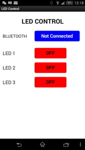 In App Inventor I had added two more buttons to control the extra LEDs
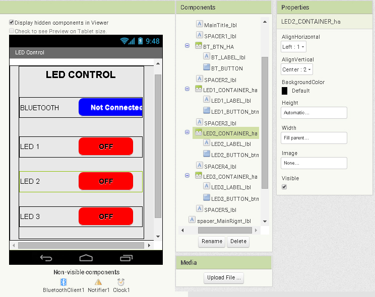
Android App
In the designer I have added two horizontal arrangements. These are containers for the LED labels and LED buttons.
The App Inventor 2 aia file can be downloaded at the bottom of the page.
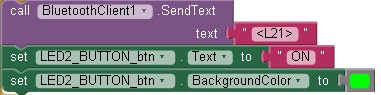
To handle the 2 new buttons there are 2 extra button click event functions. One function for button #2 and one for button #3.
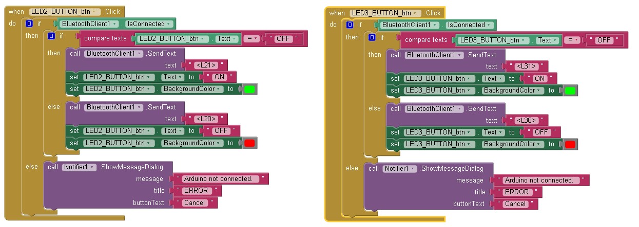
The new button click functions are copies of the button #1 click function except the references to the button have been changed so that the correct button is updated and the correct command is sent to the Arduino.
We have extra commands for the two new switches that we need to take care of:
<L20>
<L21>
<L30>
<L31>
These are handled by an extended processLEDCommand function:
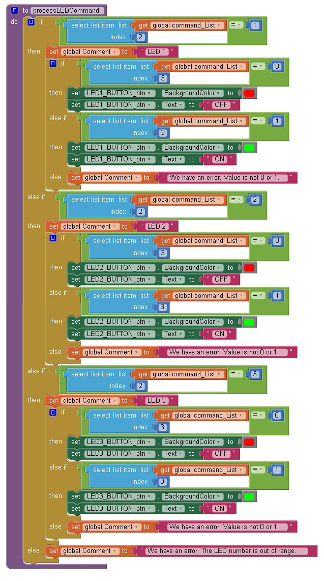
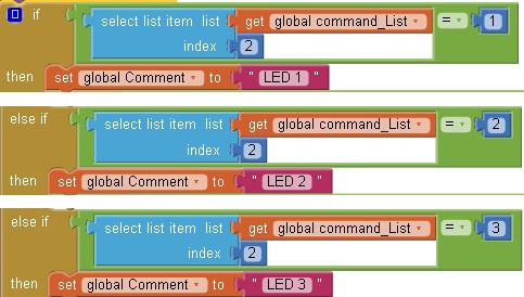
Because we have more than 1 LED we need to check to see which LED the command is for. This is done through the main if/then control. This tests for LED1, LED2 and LED3 in turn.
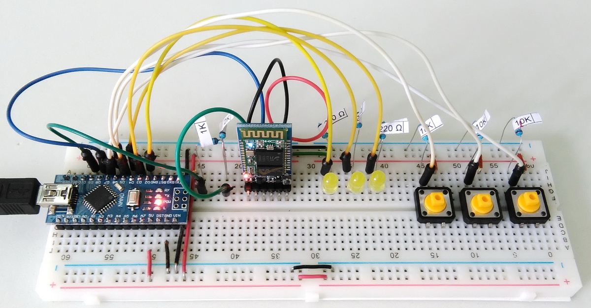
Arduino
On the Arduino side I added 2 more LEDs and 2 more switches.
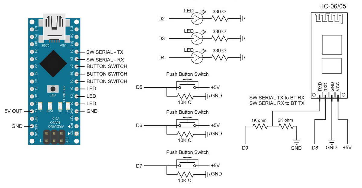
Corrected diagram. Thanks to Trieu for pointing out the mistake (I had TX and RX swapped on the Arduino).
Note: For the Leonardo, AltSoftSerial uses pins 5 and 13 for TX and RX. Thanks to Ig1 for the reminder. For other boards see the AltSoftSerial webpage
And of course the sketch needs to be updated to accommodate the extra components.
When dealing with 2 or 3 of the same component keeping the sketch simple is probably the best way to go, therefore, I simply duplicate the code used for the 1 LED and changed the references.
// Constants for hardware const byte LED1_PIN = 2; const byte LED2_PIN = 3; const byte LED3_PIN = 4; const byte SWITCH1_PIN = 5; const byte SWITCH2_PIN = 6; const byte SWITCH3_PIN = 7; // general variables boolean LED1_State = false; boolean LED2_State = false; boolean LED3_State = false; boolean switch1_State = false; boolean switch2_State = false; boolean switch3_State = false; boolean oldswitch1_State = false; boolean oldswitch2_State = false; boolean oldswitch3_State = false; |
If I were adding more of the same components, for example 6 LEDS, then I would use arrays such as:
const byte LED_PIN[] = {2,3,4}; boolean LED_State[] = {false; false, false}; boolean switch_State[] = {false; false, false}; boolean oldswitch_State[] = {false; false, false}; |
For 2 or 3 LEDs or switches I don’t see the need to complicate the code. The extra for loops required don’t really save space and make the code harder to debug. Duplicating code blocks may seem wasteful but it keeps the code as simple as possible which makes it easier to understand.
There are now extra commands and these are handled by adding extra conditions to the processCommand() function. Again, I have kept it simple and just duplicated the existing code and changed the values to accommodate LED2 and LED3. L10 becomes L20 and L30, etc.
if (strcmp ("L10",receivedChars) == 0) { digitalWrite(LED1_PIN,LOW); LED1_State = LOW; Serial.println("LED1 LOW"); } else if (strcmp ("L11",receivedChars) == 0) { digitalWrite(LED1_PIN,HIGH); LED1_State = HIGH; Serial.println("LED1 HIGH"); } else if (strcmp ("L20",receivedChars) == 0) { digitalWrite(LED2_PIN,LOW); LED2_State = LOW; Serial.println("LED2 LOW"); } else if (strcmp ("L21",receivedChars) == 0) { digitalWrite(LED2_PIN,HIGH); LED2_State = HIGH; Serial.println("LED2 HIGH"); } else if (strcmp ("L30",receivedChars) == 0) { digitalWrite(LED3_PIN,LOW); LED3_State = LOW; Serial.println("LED3 LOW"); } else if (strcmp ("L31",receivedChars) == 0) { digitalWrite(LED3_PIN,HIGH); LED3_State = HIGH; Serial.println("LED3 HIGH"); } |
Since we are using fixed length commands we know that the first character is the command type, in this case L for LED, the second character is the LED number and the third values is either a 0 or a 1 (off or on). This means we could use a slightly different if/then structure:
if (receivedChars[0] == 'L') // Do we have an LED command? { if (receivedChars[1] == '1') // Is the command for LED number 1? { if (receivedChars[2] == '0') // Is the LED off? { digitalWrite(LED1_PIN,LOW); LED1_State = LOW; Serial.println("LED1 LOW"); } else if (receivedChars[2] == '1') // Or is the LED on? { digitalWrite(LED1_PIN,LOW); LED1_State = LOW; Serial.println("LED1 LOW"); } } // We already know we have an LED command so no need to recheck. if (receivedChars[1] == '2') // Is the command for LED number 2? { if (receivedChars[2] == '0') // Is the LED off? { digitalWrite(LED2_PIN,LOW); LED2_State = LOW; Serial.println("LED2 LOW"); } else if (receivedChars[2] == '1') // Or is the LED on? { digitalWrite(LED2_PIN,LOW); LED1_State = LOW; Serial.println("LED2 LOW"); } } // code for LED #3 not shown. } |
However, this is still slightly cumbersome and not as easy to read. When using
if (strcmp ("L10",receivedChars) == 0) |
you can see straight away what is happening. The code is looking for “L10”; is it LED #1 and is it off?
Likewise for the checkSwitch() function. I duplicated the code for the extra switches. This means there are 3 code blocks that are almost identical but it keeps it easy to read.
void checkSwitch() { // Simple toggle switch function with very simple debouce. boolean state1 = digitalRead(SWITCH1_PIN); delay(1); boolean state2 = digitalRead(SWITCH1_PIN); delay(1); boolean state3 = digitalRead(SWITCH1_PIN); delay(1); if ((state1 == state2) && (state1==state3)) { switch1_State = state1; if ( (switch1_State == HIGH) && (oldswitch1_State == LOW) ) { LED1_State = ! LED1_State; if ( LED1_State == HIGH) { BTserial.print("<L,1,1>" ); digitalWrite(LED1_PIN,HIGH); Serial.println("Sent - <L,1,1>"); } else { BTserial.print("<L,1,0>"); digitalWrite(LED1_PIN,LOW); Serial.println("Sent - <L,1,0>"); } } oldswitch1_State = switch1_State; } // Simple toggle switch function with very simple debouce. state1 = digitalRead(SWITCH2_PIN); delay(1); state2 = digitalRead(SWITCH2_PIN); delay(1); state3 = digitalRead(SWITCH2_PIN); delay(1); if ((state1 == state2) && (state1==state3)) { switch2_State = state1; if ( (switch2_State == HIGH) && (oldswitch2_State == LOW) ) { LED2_State = ! LED2_State; if ( LED2_State == HIGH) { BTserial.print("<L,2,1>" ); digitalWrite(LED2_PIN,HIGH); Serial.println("Sent - <L,2,1>"); } else { BTserial.print("<L,2,0>"); digitalWrite(LED2_PIN,LOW); Serial.println("Sent - <L,2,0>"); } } oldswitch2_State = switch2_State; } // Simple toggle switch function with very simple debouce. state1 = digitalRead(SWITCH3_PIN); delay(1); state2 = digitalRead(SWITCH3_PIN); delay(1); state3 = digitalRead(SWITCH3_PIN); delay(1); if ((state1 == state2) && (state1==state3)) { switch3_State = state1; if ( (switch3_State == HIGH) && (oldswitch3_State == LOW) ) { LED3_State = ! LED3_State; if ( LED3_State == HIGH) { BTserial.print("<L,3,1>" ); digitalWrite(LED3_PIN,HIGH); Serial.println("Sent - <L,3,1>"); } else { BTserial.print("<L,3,0>"); digitalWrite(LED3_PIN,LOW); Serial.println("Sent - <L,3,0>"); } } oldswitch3_State = switch3_State; } } |
Condensing the code
Although I have just advocated keeping the code as simple as possible you can see that the above has 3 code blocks that are almost exactly the same. This could be made better by using single code block with a variable for the switch pin and by using arrays for the switch variables and passing the pin for the switch to check to the function.
Let’s see what it would look like.
First off we put the pin values and status variables in to arrays:
// Constants for hardware const byte LED_PIN[] = {2,3,4}; const byte SWITCH_PIN[] = {5,6,7}; // general variables boolean LED_State[] = {false,false,false}; boolean switch_State[] = {false,false,false}; boolean oldswitch_State[] = {false,false,false}; |
Since we now have arrays we can use them when initialising the pins:
void setup() { for (byte pin = 0; pin < 3; pin++) { // Set the button switch pins for input pinMode(SWITCH_PIN[pin], INPUT); // Set the LED pins for output and make them LOW pinMode(LED_PIN[pin], OUTPUT); digitalWrite(LED_PIN[pin],LOW); } |
In the main loop we now use a loop when checking the switches and we pass the switch number to the checkSwitch() function. Rather than checking all 3 switches in one go we now check one at a time by telling the function which one to check.
You could move the for loop to inside the checkSwitch() function and call it just once if you liked but this would make the function less flexible. You couldn’t, for example, check a single switch.
void loop() { for (byte switchNum = 1; switchNum < 4; switchNum++) { checkSwitch(switchNum); } recvWithStartEndMarkers(); // check to see if we have received any new commands if (newData) { processCommand(); } // if we have a new command do something about it } |
In the checkSwitch() function we now create the commands on the fly rather than having 3 sets of commands hard coded in to the sketch. The command is created by using a dummy command and then replacing the LED number and the LED status.
We now have the following and although it is much shorter it is also harder to understand.
void checkSwitch( byte pos) { // pos = 1,2,3. Array pos = 0,1,2 so convert by subtracting 1 pos = pos-1; // very simple debouce. boolean state1 = digitalRead(SWITCH_PIN[pos]); delay(1); boolean state2 = digitalRead(SWITCH_PIN[pos]); delay(1); boolean state3 = digitalRead(SWITCH_PIN[pos]); delay(1); if ((state1 == state2) && (state1==state3)) { switch_State[pos] = state1; if ( (switch_State[pos] == HIGH) && (oldswitch_State[pos] == LOW) ) { LED_State[pos] = ! LED_State[pos]; // flip the status. char TMPcmd[8] = "<L,1,0>"; TMPcmd[3] = pos+1+48; // pos+1 is the LED number; 1,2, or 3. // Convert a numeric value to ascii by adding 48 TMPcmd[5] = LED_State[pos]+48; // LED_State should be 0 or 1 BTserial.print(TMPcmd); digitalWrite(LED_PIN[pos],LED_State[pos]); Serial.println(TMPcmd); } oldswitch_State[pos] = switch_State[pos]; } } |
And in the processCommand() function we have done away with the long list of if/thens and reduced it to just a few lines.
void processCommand() { Serial.print("receivedChars = "); Serial.println(receivedChars); if (receivedChars[0] == 'L') // do we have a LED command? { // we know the LED command has a fixed length "L10" // and the value at pos 1 is the LED and the value at pos 2 is 0 or 1 (on/off). // 0 and 1 is the same as LOW and HIGH. byte LEDnum = receivedChars[1] - 48; // convert ascii to value by subtracting 48 boolean LEDstatus = receivedChars[2] - 48; digitalWrite(LED_PIN[LEDnum-1],LEDstatus); LED_State[LEDnum-1] = LEDstatus; } receivedChars[0] = '\0'; newData = false; } |
This could be reduced further by removing the LEDnum and LEDstatus variables but you would end up with
digitalWrite(LED_PIN[(receivedChars[2]-48)-1],receivedChars[2]-48); LED_State[(receivedChars[1]-48)-1] = receivedChars[2]-48; |
and in a months time I will have no idea what it does.
Download
Download the App Inventor 2 aia file and the 2 Arduino sketches.
WHY AM I ALWAYS FAIL? IS THERE SOMETHING WRONG?
Please describe what problems you have or what is not happening?
Is the BT module configured and connected correctly, have you have basic communication working between an Android app and the Arduino?
Can you compile and load the Android app correctly?
Connected ok but when control, nothing happened, asking about rx and tx, can i connected rx and tx from hc05 to aduino nano?
and can i replace led by relay module?
Did you do the earlier examples and have you had basic communication working?
Yes, actually i did it ok with one way from ai2 to control arduino, but have problem can not get data from ardui o to change colour of button ai2 and receive status when control arduino side, can u give me your facebook name? Thanks
ohhh it ok when i changed between Tx and Rx from hc05, not as ur schema.
And can u show me how to get status from arduino: example when we have 1 led on and when i connected it not show on my phone until i press it?
Hi dear , can i arduino uno with this project ,thanx
Yes.
I cannot find the Teensy board on my Arduino. Can this really work at UNO?
yes. If using AltSoftSwerial check which pins are used.
I can’t upload the code to my arduino. Why is that?
NO CARGA EL SKETCH EN ARDUINO NANO
Sorry sir, but can help me this problem. all woriking with your post but have problem:
1. when connected , i turn on led on my phone, led is on after that i press button, but i must press 2 time to turn it off, all for 3 button (it not update status of led pin out by android)
2. turn on 2 led after that i connected by android, but in android not update 2 led on already.
Can u help me solve 2 problem, many thanks to you..
it sounds like the phone is are not receiving the commands from the Arduino. Check the wiring between the Arduino and the BT modules. If you still have problems try one of the earlier examples and get basic 2 way communication working.
I try to upload this code to Arduino Mega2560 but uploading not done
Witch arduino can i use for this project
I have some proplem in the code it give this error: –
C:\Users\yazan\Documents\Arduino\sketch_feb26a\sketch_feb26a.ino: In function ‘void loop()’:
sketch_feb26a:26: error: ‘recvWithStartEndMarkers’ was not declared in this scope
recvWithStartEndMarkers(); // check to see if we have received any new commands
^
sketch_feb26a:27: error: ‘newData’ was not declared in this scope
if (newData) { processCommand(); } // if we have a new command do something about it
^
C:\Users\yazan\Documents\Arduino\sketch_feb26a\sketch_feb26a.ino: In function ‘void checkSwitch(byte)’:
sketch_feb26a:50: error: ‘BTserial’ was not declared in this scope
BTserial.print(TMPcmd);
^
C:\Users\yazan\Documents\Arduino\sketch_feb26a\sketch_feb26a.ino: In function ‘void processCommand()’:
sketch_feb26a:60: error: ‘receivedChars’ was not declared in this scope
Serial.print(“receivedChars = “); Serial.println(receivedChars);
^
sketch_feb26a:75: error: ‘newData’ was not declared in this scope
newData = false;
^
exit status 1
‘recvWithStartEndMarkers’ was not declared in this scope
are you using the complete sketch?
Hi. I use Arduino Leonardo and I have a problem with serial communication. I also tried the code from the second part, the same problem. Do you have any solution for Leonardo board.
Hi. I use Arduino Leonardo and I have a problem with serial communication. I also tried the code from the second part, the same problem. Do you have any solution for Leonardo board?
I solved the problem. For the Leonardo in AltSoftSerial Library TX, RX is on pins (5, 13).
Verry good job! Thanks a lot.
Sir, could you please show me how to change the code to be able to use 8 LEDs without switches, but to the state LEDs was still recognized after disconnecting and reconnecting?For example: if 4 LEDs of 8 are turned on, then after leaving the android application and re-start it 4 status LEDs will be remembered as enabled. Thank you and best regards.
hi Martyn
i wish you doing well,
i’m still working on my own project but i still have issue!! i want to add another push button in the app but i couldn’t analyse this condition of check switch::
boolean state1 = digitalRead(SWITCH1_PIN); delay(1);
boolean state2 = digitalRead(SWITCH1_PIN); delay(1);
boolean state3 = digitalRead(SWITCH1_PIN); delay(1);
boolean state4 = digitalRead(SWITCH1_PIN); delay(1);
if ((state1 == state3) && (state1==state4)))??
how i could fix this
a lot of thanks
Use the bottom example, the one with arrays. Add another element to the arrays
Note – in the below I use pins 8 and 9. These are connected to the Bluetooth module.
Change the pins to suit your requirements.
———————————————————————————
// Constants for hardware
const byte LED_PIN[] = {2,3,4,5};
const byte SWITCH_PIN[] = {6,7,8,9};
// general variables
boolean LED_State[] = {false,false,false, false};
boolean switch_State[] = {false,false,false, false};
boolean oldswitch_State[] = {false,false,false, false};
———————————————————————
and then increase the limit in the relevant loops.
void setup()
{
for (byte pin = 0; pin < 4; pin++) { // Set the button switch pins for input pinMode(SWITCH_PIN[pin], INPUT); // Set the LED pins for output and make them LOW pinMode(LED_PIN[pin], OUTPUT); digitalWrite(LED_PIN[pin],LOW); } --------------------------------------------------------------------------------- void loop() { for (byte switchNum = 1; switchNum < 5; switchNum++) { checkSwitch(switchNum); } recvWithStartEndMarkers(); // check to see if we have received any new commands if (newData) { processCommand(); } // if we have a new command do something about it } ---------------------------------------------------------------------------------
thanks. i had make this change on your app but i but it doesn’t work withe me. i have got same command when i pressed the second button. so i need to fix the list index blocks>
and i want to know what is mean:
select list item list ==1>>>>index 2
select list item list==2>>>>index 2
select list item list==3>>>>index 2
select list item list==4>>>>index 2
Br
hello
i’m still working to add fourth button on the app but now response when i have change the status of the button? and i have to replace the list index number of blocks that show me the length of (L) is large there is an error !!
so help me to do this??
thanks
Hello,
What à good job !
Can you telle me thé software you use to draw jour diagramme ?
Thank you
Chris
A very old version of CorelDraw.
Hi
I make all
3 led with 3x 320 Om
3 button switch with 3 x10 K Om
1 arduino uno
1 Bluetooth H5
IT Working manual
When trying to work with app (not work ) why?
OK IT work
Thank you
how can make
a LED on and off with an Arduino, Bluetooth and Android
8 LEDs and 8 Switches
You could do this using only an Arduino but it would use all the pins including using the analogue pins as digital pins.
I would suggest looking at an LED matrix and possibly a voltage ladder for the switches. These are beyond the scope of this post but google will give you many links. The LED matrix does not have to look like a matrix. You could have all the LEDs in a line.
For the software, the above example should be scalable. Just extend the arrays.
can help me with code
I’m sorry I can’t. But learning to do this yourself will give you a better understanding of programming the Arduino.
You can also ask on the Arduino forum but I doubt anybody will help with the actual code.
how can learning to do that?
Break your project down in to the basic tasks, for example,
– switch
– LED
Then google Arduino + Switch
Arduino + LED
And learn the basics for checking the state of a switch and how to turn LEDs on and off.
Do the same for App Inventor 2.
Also look at the code in the part 2 guide. Try to figure out how it works. Then compare it to the code above.
ok i do that
whay you but resistance?
only for protection?
or there is something else
TWO_WAY_LED_CONTROL_3_LEDS.ino:26:27: fatal error: AltSoftSerial.h: No such file or directory
compilation terminated.
Error compiling.
plz sir whats the problem
you need to add the AltSoftSerial library
thanks sir
sir is this project work with aruino mega ??
becuse it dosnot work with me
thanks sir
AltSoftSerial uses different pins on the MEGA:
TX – 46
RX – 48
When using AltSoftSeriasl PWM is not available on 44 & 45
Or better to use one of the additional hardware serials.
thinks sir
only i have one proplem the app not read button State
oh i fix it sir thanks agane for this
Hello sir.. Can i control 3 led with 3 buttons by using arduino master slave bluetooth ? If yes, please teach me to do it.. I dont know how to do it, because i search from the internet, it only show 1 led controlled by using master slave.. Itsame with this project , but mine has 3 buttons on master and 3 led on slave by using bluetooth hc05 module.. Is it possible to made it ? If yes.. Please show me how to do it
Thank you for this very beautiful and very useful project.
I’m not familiar with the inventor’s waste of course but the project worked ok.
I tried to adapt it to an esp 8266 module because I also have TX / RX and I can go directly from the WI / FI network but my bad knowledge about the inventor has made a mistake.
I can not find the WI / FI connection command in the inventor …
In fact, my phone is connected all the time to Rooter and esp-8266 is also connected to the router, so the connection function would be useless at WI / FI.
I can not find commands that can talk with rooters, that is to send the command to the rooter and esp to receive it again by TX / RX to talk with arduino.
Which can do by sending commands from the brauser or the phone in the form of: 196.128.0.6/on1 or rest of the commands that esp receives them and transmits them to arduino or esp 8266-12 would have enough pins to execute the commands without Arduino.
Most of the help I get to receive the reverse confirmation on the phone, that is, the button status so with arduino i would like to make the + esp8288 device.
Please tell me the inventor is able to do exactly what he does with the BT module but with an ESP module? Or I am disappointed and believe in something that can not be achieved with this online inventory program. I find very interesting your sin work that I did not find with esp and arduino the same :)
My interest in ESP would be that I can see it from a distance: service “if the light stays lit and I can close it directly with the phone. So I could save energy and for me it would be the biggest thing :))
Maybe you can tell me if it can be done with ESP and if possible an example in the inventor with 2 nutaane at least the following I can add the rest as needed :)
Thank you for this great project
AI2’s web component works in a very different way. There are 2 main ways of connecting.
1 – via a web page.
2 – via an app using the web component
I have a guide that covers creating a web page to control an LED at https://www.martyncurrey.com/esp8266-and-the-arduino-ide/. Note that this uses the Arduino IDE to program the ESP8266.
To find out more about using a web connection from inside an app start with the guides on the AI2 website or search for something like “app inventor web” and “app inventor esp8266”.
i finally found something that can help. i have bluetooth rgb led rock light on my truck and i currently turn them on/off cange colors with an app on my phone. i want to get rid of the app on my phone and control the lights with buttons mounted to in my truck. i was thinking with bluetooth arduino with buttons attached to it sync it up with the lights and just push buttons to control the lights. very new to arduino and coding and stuff im hoping you can help me.
Hello,
Can you send my design block for global command list?
I cannot able to make a list with 3 index.
My e-mail id is arungoyal47@gmail.com
i want to add 1more switch in arduino code. so pls help me. i dont know arduino coding
Hello sir
how to add eeprom of arduino to this project to save last status of led after restarting app
i have added 8 leds to this project using arduino mega .when i pressed led1 button it show 2 leds on in app.please help me
check –
what command is being sent when you press button #1
what your sketch does when it gets a LED 1 command.
Dear Mr. Martyncurrey, I am 72 years retired Telecom Engineer and my hobby is home automation. Thank you for publishing wide range of interesting projects and my hearty thanks for your help to the community.
I need your help to change the momentary switch to on/off switch for sensing the garage door status and update it is Closed or Opened.
How do I change the Toggle function to ON/OFF function to use reed switch.
Please Help Me.
With Great Regards and thanks once again,
ragoth@gmail.com
this is beyond the scope of the site but you can think of the reed switch as a regular switch. It is either open or closed.
Experiment, replace a button switch with the reed switch and see what happens when you move it.
Can i ask if this programme can work also for only one led and 1 button ?
Hello
I am French and I use the automatic translation …
Well done for your work, but I have a problem:
I installed without modifying the Arduino program in my NANO and the latest program for APP INVENTOR.
My Android sends the information to Arduino (Leds on / off, but when I turn off or on an LED with the buttons of the Arduino, no change appears on my mobile, problem on the bidirectional,
On the other hand I see the information on the series management of the arduino.
With the other programs (No. 2) for example, it’s the same problem.
I checked my connections buttons, it seems to me well.
Do you have an opinion please?
To know that I use arduino NANO and a HC-06 module that works.
Thank you in advance for your opinion
I answer myself, it was a mistake on my part in the resistance values on RX to the GND, the problem is solved, and everything works perfectly …
Congratulations for your work
Hello
When I connect in Bluetooth with the mobile phone, I would like the buttons of the leds on the mount to be in real state (lit or not) at the time of the Bluetooth connection.
It is probably necessary to put in the “void loop ()” digitalRead (LED1_PIN), and LED2_PIN, and LED3_PIN on arduino, but I go around in circles, I can not know what to put in the program App Inventor, I use your arduino sketch: “TWO_WAY_LED_CONTROL_3_LEDS.ino” and your App Inventor program: “TWO_WAY_LED_CONTROL_3_LEDS”.
Thank you for being able to help me please?
You have probably realized you need to do this after a connection is made. The way I handle this in actual projects is to have a handshake/connection command. I then use the receipt of the connection command to trigger an initializing procedure.
1 – make the bluetooth connection
2 – send a “HELLO” message
3 – when receive “HELLO” message do bluetooth set up stuff
All the bluetooth set up stuff is in it’s own function and only called when the “HELLO” message is received.
Thank you, that’s it, I managed to recover the answer of the arduino on the laptop (app inventor). In fact it was simple …
It was enough to create a button of initialization, and to put the conditions to exploit, I clashed with the number of byte to send the arduino and to receive with app inventory the exact number of byte (number of characters received)
it works very well
Thank you
sir i cant search android app
im trying to follow exactly the program you provided but it comes error message ‘btserial’ was not declare.
can you help me
It sounds like you have either; not included the AltSoftSerial library or you forgot to initialize the software serial.
hello sir,
In download, Aia file is not Available. From where should i download.
will wait for your reply.
Thank you.
I am really sorry.
I got the file.
Thank you
How to change 8 TX,9 RX to 1 Tx,0 RX
The above examples use the AltSoftSerial library which must use pins 8 and 9.
If you want to use the hardware serial then change AltsoftSerial to Serial in the sketch and change the pins.
HI
thank you for providing such a good project. it help me a lot
all working fine but when i press the switch led ON but not show current status on APP button
Did you try one of the earlier simpler examples and did they work?
Check the connection – BT TX to Arduino RX
Use the serial monitor to see what, if anything, is arriving from the Bluetooth module.
yes sir, they work fine but same problem occur in both program
when i press the switch 1 it show “sent in serial monitor same as remaining switches
when i press APP button it show receivedChars “L11”
but not show status of led when i pressed switch in APP
I connected TX and RX of BT to Arduino Pin 8 and 9
the problem is they don’t update LED 1 on or off on android and LED 2 and LED 3 work great. All checks in code and in MIT and all commands for LED 1 are the same as for the other two LED
Because LED 2 and 3 are working it sound like you have a connection issue with LED1. Check your connection for LED1, also check the LED and the resistor value.
Please review the recording https://files.fm/u/zgs9nj4q
it looks like a problem with the command being sent to the Android app.
– check the sketch; check the command that is actually sent (check for typos).
– check the app; what command is it receiving? Are you checking for the correct command? (check for typos).
http://prntscr.com/qoyij2
http://prntscr.com/qoyizi
The commands look OK.
All I can suggest now is to swap the switches around. Change the pins so that switch 1 becomes switch 2 and switch 2 becomes switch 1.
change
const byte SWITCH1_PIN = 5;
const byte SWITCH2_PIN = 6;
const byte SWITCH3_PIN = 7;
to
const byte SWITCH1_PIN = 6;
const byte SWITCH2_PIN = 5;
const byte SWITCH3_PIN = 7;
If the problem persists on LED1 then there is an issue with the code somewhere.
If LED2 stops working but LED1 works then there is an issue with the hardware somewhere
my mistake, uploading a sketch for 5 relays remained on the atmega and I connected 3 relays so switch1 is not well mapped to the sketch the wrong pin is typed.
Many thanks for the prompt replies. Your tutorials are extremely good.
Thanks a lot and all the best
Glad you have it working.
in this can you add eeprom bro
please provide code and circuit diagram
can we use the same pin for LED pins and switch pins
while technically possible through careful programming and careful considerations with the circuit it is probably not worth it.
Tengo un problema, todos los leds funcionan tanto con los botones switches y con el app inventor apk, pero cuando presiono el boton fisico no me muestra el estado de encendido o apagado en mi teléfono celular, yo hice con sensor táctil TTP223, y también con Sensor infrarrojo IR FC-5, funciona muy bien. muchas gracias por tu proyecto.
Great video sir, right now I’m making this project but I’m using Nano everything board I tried to upload the code it’s not compatible with the every would I need upload a new sketch?