Update 19.09.2015
The FC-114 boards I have have the Bolutek firmware. User DS has reported that he/she has FC-114 boards that have the linvorV1.8 firmware. So if the below does not work for you then check what firmware you have.
Since the HC-05 FC-114s and the HC-06 FC-11s share the same firmware the following should work on either module.
The default setting on start up is Slave Mode waiting for pairing or a connection and also accepting AT commands. This means it is fairly simply to start using AT commands.
Connections
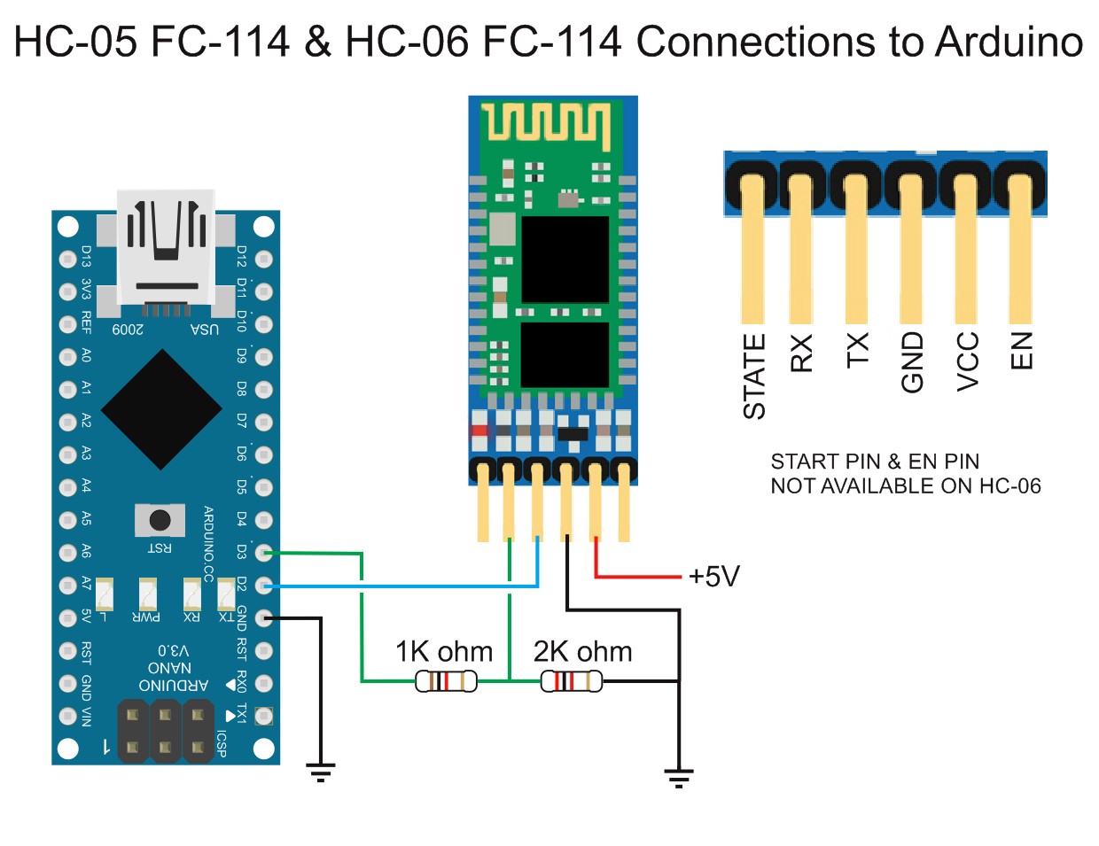
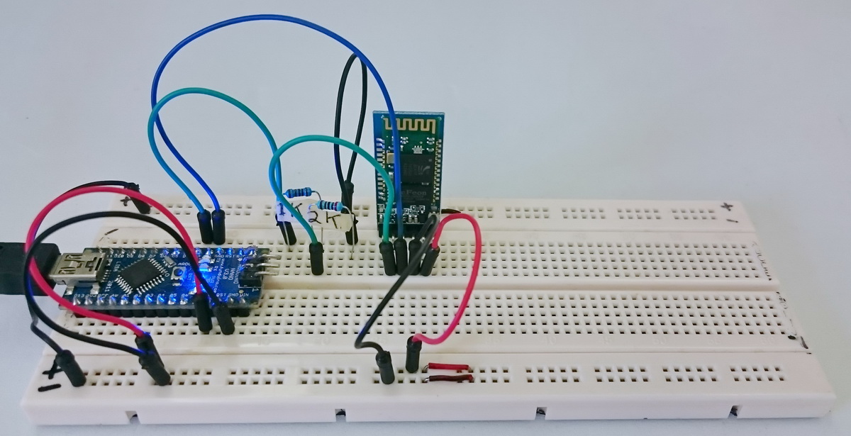
The connections are the same as other HC05 and HC-06 modules
– Arduino D2 to BT TX
– Arduino D3 to voltage divider and then to BT RX
– Arduino 5v out to BT vcc in
– GND to GND
Sketch HC-0x_FC-114_01_9600
Once you have made the above connections upload the following sketch. The sketch takes anything entered in to the serial monitor and sends it to the Bluetooth module. It also copies anything received from the Bluetooth module to the serial monitor. It also echos the user input in the serial monitor back to the serial monitor main window.
// Basic bluetooth test sketch. HC-0x_FC-114_01_9600
// Uses hardware serial to talk to the host computer and software serial for communication with the bluetooth module
//
// Pins
// BT VCC to Arduino 5V out.
// BT GND to GND
// Arduino D3 to BT RX through a voltage divider
// Arduino D2 BT TX (no need voltage divider)
//
// When a command is entered in the serial monitor on the computer
// the Arduino will relay it to the bluetooth module and display the result.
//
// The HC-0x FC-114 modules require CR and NL
#include <SoftwareSerial.h>
SoftwareSerial BTSerial(2, 3); // RX | TX
char c = ' ';
boolean NL = true;
void setup()
{
Serial.begin(9600);
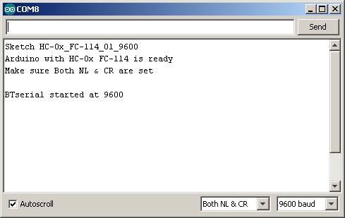
Serial.println("Sketch HC-0x_FC-114_01_9600");
Serial.println("Arduino with HC-0x FC-114 is ready");
Serial.println("Make sure Both NL & CR are set");
Serial.println("");
// FC-114 default baud rate is 9600
BTSerial.begin(9600);
Serial.println("BTserial started at 9600");
Serial.println("");
}
void loop()
{
// Read from the Bluetooth module and send to the Arduino Serial Monitor
if (BTSerial.available())
{
c = BTSerial.read();
Serial.write(c);
}
// Read from the Serial Monitor and send to the Bluetooth module
if (Serial.available())
{
c = Serial.read();
BTSerial.write(c);
// Echo the user input to the main window. The ">" character indicates the user entered text.
if (NL) { Serial.print(">"); NL = false; }
Serial.write(c);
if (c==10) { NL = true; }
}
}
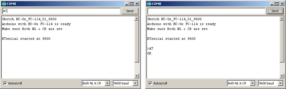
After uploading open the serial monitor and you should see the following
To confirm AT commands are working enter “AT” and hit Send.
You can also check the firmware version using “AT+VERSION”
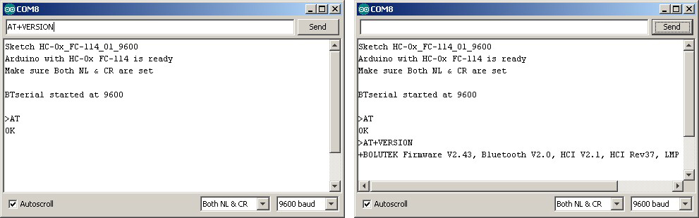
The modules I have report the firmware as
+BOLUTEK Firmware V2.43, Bluetooth V2.0, HCI V2.1, HCI Rev37, LMP V4, LMP SubV37
To get a list of the available At commands enter AT+HELP and hit Send
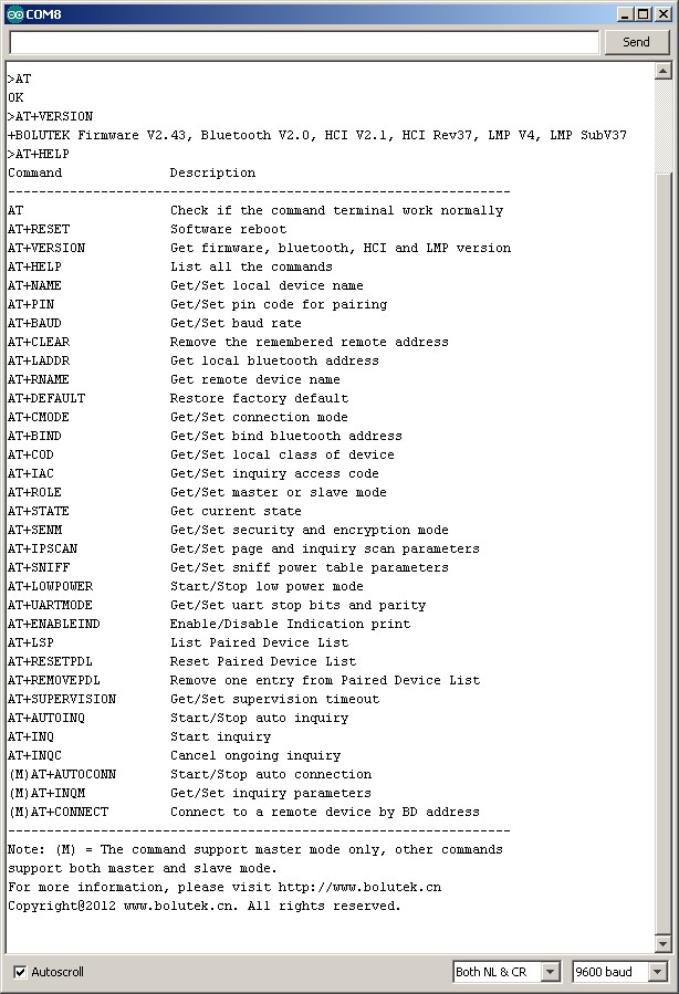
And that’s all there is to it.
For more details about the AT commands look at the BLK-MD-BC04-B At Command user guide.
In the bluetooth module FC 114, there is an EN pin. What is the use of that pin and where do I connect it with arduino uno . How do I use that bluetooth module in master mode while pairing it with other bluetooth module ( PI 05).
Connect the EN pin to GND to disable the module.
More info at https://www.martyncurrey.com/hc-05-fc-114-and-hc-06-fc-114-part-3-master-mode-and-auto-connect/
I don’t have a write up on connecting the FC114 module but have a look at https://www.martyncurrey.com/connecting-2-arduinos-by-bluetooth-using-a-hc-05-and-a-hc-06-pair-bind-and-link/. This should help.
Thank you for your quick reply. This would be more helpful.
Hi,
I also got fc-114s, and having some troubles.
As you know, it is easy to enter the AT mode, but in my case AT commands do not work.
only the test command, ‘AT’ works, and I can see ‘OK’ on the screen. (I’m using Tera Term with USB serial connector)
other AT commands,
AT+VERSION
AT+INQ
AT+…
no responses at all..
as you mentioned in this article, there are not many docs about this fc-114
Do you have any idea about this problem?
thanks in advance.
Since few time i got a fc-114 so i’m not an expert but to have responses, i have to press the button just above the EN pin on the bluetooth module, during sending the AT commande (keep press during send the command)
Hope it can help..
MY PROBLEM WAS SOLVED:
I had the same problem. When I sent whatever AT command I never got a response. But I did what Greg wrote. I pressed the button above the EN pin, on the bluetooth device.
When I want to send a command I have to press that button and I hold it pressed while I send the command. That is the only way which my arduino uno and hc05 works. Thanks a lot.
My issue solved by pressing the button.
Thanks!
I assume if AT is working then you have Both NL & CR set but please double check.
does AT+HELP work?
Have you also looked at
https://www.martyncurrey.com/hc-05-fc-114-and-hc-06-fc-114-first-look/
Thank you for your reply,
I tried some AT commands,
(I wrote these commands into notepad, and ‘copy and paste’ it, if I enter AT commands with keyboard, only ‘AT’ works, like ‘ATOK’)
anyway, I pasted ‘AT+VERSION’ and HC-05 immediately returns ‘OK’ and ‘linvorV1.8’
‘AT+VERSIONOKlinvorV1.8’
and ‘AT+HELP’ does not work. it is weird..hmm..
thanks
OK. You don’t have the FC-114 modules. You have a different version, possible the JY-MCU. It is also possible that you have a HC-06.
Can you post a photo somewhere or link to a picture of the same device.
How many pins does the module have?
What markings are on the module?
Thanks Martyn,
at first, I do have FC-114s because it is written on it haha
anyway, I found some useful tips, and I think it is working. I managed to send some data from my android phone to FC-114.
Thank you for your help.
(http://arduinosensors.com/index.php/2014/07/)
Thanks,
I guess the manufactures are using the same break out boards for different BT modules. The boards I have all have the Boulutek firmware. The linvorV1.8 firmware is one of the standard firmwares and has been mostly found on boards like the JY-MCU.
Going forward it may be better to get the firmware version first and use that rather than the model number printed on the board.
If you have the OKlinvorV1.8 , There are a couple of things:
1) It takes forever for these things to generate a response. Can be almost a second to even get ‘OK’ from the AT.
2) You can’t really use a terminal program because the commands “timeout”. What I mean is, if you type A…T… (… = slow typing) you won’t get a response. So you need to use something like the Arduino terminal or python and pyserial. This is actually what I used. Plus, my module had no button, so I had to pull up the enable (or rather, I just connected it to 5V… but really you should connect it to 3.3V). Also, most of the commands aren’t really available. I don’t know which commands ARE available, but I’ll try AT+HELP and see if that even works.
Hi, im having a lot of trouble with this HC-05 FCC-114 module, even with your method, could it be the Arduino IDE? or my OS WIN 8.1 x64… im going crazy :((
About AT mode, double checked everyting, baud rate, NL & CR, tried both 9600 and 38400 baud and LED shows it is actually in AT mode by blinking once every 2 sec, i kept the button on the corner pressed before powering, to achieve that, but no AT commands work for me, not even ‘AT’ or ‘AT+VERSION’ nothing… could it be related to the button on the corner? because i read somewhere that you need to keep it always pressed.
Also tried using it without touching any AT command and module seems functional, LEDs are blinking as they should and also pairing and sending data from the module to a smartphone works fine, i used Bluetooth Terminal app to test it, it is able to send data to the phone, but nothing sent from my phone reaches the module and im really confused about why is that happening if everything else seems correct.
I would be really thankful if you could give me some help, im running out of time with this project and im new to these bluetooth modules :(
It does appear that the manufacturers are using different bluetooth modules on the same breakout board and the first step should be to try an identify the firmware. It could be Bolutek (same as me) or it could be linvorV1.8. It may even be something else.
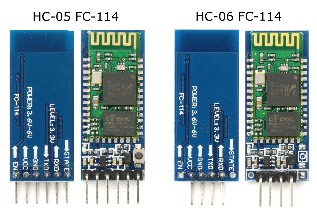
The push button switch connects pin 34 of the small BT module to +3.3v. So far, I have found this works only on the zs-040 modules with the 2.0-20100601 firmware. On the modules you have, is pin34 connected? Pin34 if top right. If you look at the photos above you can see that pin34 is not connected (no solder) on the boards I have. See https://www.martyncurrey.com/wp-content/uploads/2015/08/HC-05_FC-114__HC-06_FC-114_001_1600.jpg
Connect the module using the above diagram and then, while connected to the Arduino, with the Arduino on and with the serial monitor open, reset the BT module (remove power, reconnect to power). You should get some kind of start up message. If you do not, change the baud rate and try again. Try 9600, 38400 and 115200. If you get garbage characters then you have the wrong baud rate.
If this still does not work follow the instruction at https://www.martyncurrey.com/arduino-and-hc-06-zs-040/. This should work if you have the linvorV1.8 firmware.
If you find you have the linvorV1.8 firmware then you have an HC-06 and this acts differently.
What name does the module use, what name is broadcast when you pair it?
If you have the Bolutek firmware (same as me) then the push button doesn’t do anything and you can use AT commands straight away.
What name is broadcast
THANKS A LOT for the fast reply, i’ve tried step by step and got the following results.
Pin 34 looks connected, since it clearly has solder on top.
Also tried resetting the module using every baud rate you sugested, and still no response at all to any AT commands, nor a startup message, im using same baud rates in both sentences Serial.begin(); and BTSerial.begin() (because that was the only way i got the bluetooth terminal test, to actually show something on the serial monitor) or should they be different one from the other? for example
Serial.begin(9600) BTSerial.begin(38400)…
By the way i checked the HC-06 link you said, and my module looks identical with the MX chip on top, but breakout board says FC-114 and the module LED behaves like an HC-05 since it blinks twice when paired, its never constantly on… the first time i scanned with a phone, broadcast said ‘HC-05’ but after reseting it started broadcasting ‘H-C-2010-06-01′, noticed the ’06’ in there but looked more like a date to me…
if you know anything else i could try, ill be waiting, but again thanks for the fast reply, and keep it up, your page is great and the only one that explains everything in such a detailed way.
If the board was an HC-06 then I think you would have got AT to work by now (did you remember to set “No line ending” in the serial monitor?) .
If pin34 in connected then you may have the 2.0-20100601 firmware. If you look at the photos of mu FC-114 boards pin 34 is not connected as it is not required. 2.0-20100601 is the firmware I have on the zs-040 boards. Have a look at https://www.martyncurrey.com/arduino-with-hc-05-bluetooth-module-in-slave-mode/ and https://www.martyncurrey.com/arduino-with-hc-05-bluetooth-module-at-mode/ see if these help.
I have changed the name, but if I remember correctly, the zs-040 boards I have had the name ‘H-C-2010-06-01′ when first purchased.
Do you have a usb serial adapter, something like http://www.rctech.se/index.php?route=product/product&product_id=190 (picked at random) so that you can remove the need for the Arduino and concentrate on solely on the bluetooth module?
If not already a member, join the Arduino forum (http://forum.arduino.cc/). There are people on there, especially Nick_Pyner, that can also help and may have different suggestions.
Hi..
AT mode is not detecting perfectly at the master if we use your code…
But it is detecting perfectly when we are using the just
void setup(){
}
void loop{
}
how can we overcome this and make the AT mode detect perfectly?
Hellow , I’m using FC-114 HC-05 pin34 is connect,
when I enter an AT command, it give no response just the letters in typed in.
Hello I’m using a FC-114 HC-05 the pin34 is connect.
when I type “AT”, it only shows “AT”.
The AT you see is from the Arduino and it seems like the BT module is not connected correctly. Check all the connections. Also check that you have “Both NL & CR” selected in the serial monitor.
A quick way to check;
connect the BT module to the Arduino,
load the above sketch,
open the serial monitor and cycle the power to the BT module.
If the BT module is connected correctly you will get a welcome message from the BT module. If you get garbage characters you have the wrong baud rate. Note that not all the BT modules have the same default baud rate and you may need to try several.
hii,
i m using arduino uno ,
what should i do?
The Uno should work in the same way the Nano works.
Just use the same pins to make the connection.
hi again,
Thanx for that support .But can u specify which pins in uno.
I used D3- PD-3(INT1){UNO-pin3}
and D2-PD-2(INT0){UNO_pin2}
D2 for Arduino RX and D3 for Arduino TX. remember these cross over when connecting to the BT module:
Arduino RX to BT TX
Arduino TX to BT RX.
If this is not working check the connections, especially the resistors used in the voltage divider.
You can also change the pins. Look at the SoftwareSerial command, you can change the pins to suit your project.
#include
SoftwareSerial BTSerial(2, 3); // RX | TX
If you are still having problems try different baud rates. 9600 is usually the default but yours could be different. Try 38400 first.
It is also possible that you have a different firmware.
Hi! I’m having issues with the 6-pin version. I connected every pin correctly, tried connecting rx through potentiometer, and both (rx and tx) signals through logic level converter, but neither of ways seems to work. The main issue is when I send the “AT” command in serial monitor, it doesn’t return anything. Everything in the serial monitor is set correctly, the “both NL & CR”, and 9600 baud rate. The LED is blinking repeatedly in even amounts of time. What am I doing wrong?
First, triple check all the connections and see if you can get simple communication working. Try the second example from this post https://www.martyncurrey.com/arduino-with-hc-05-bluetooth-module-in-slave-mode/.
If this works then this confirms the connections are OK. In which case you may not have the same firmware and may need to bring the BT module in to AT mode. If the board at a small button switch follow the guide here https://www.martyncurrey.com/arduino-with-hc-05-bluetooth-module-at-mode/
It looks like the same boards have different firmwares and most work differently to the Bolutek firmware mentioned above.
Hello I’m using a FC-114 HC-05 AND IM TRYING TO CONNECT THE FC-114 HC-05 TO AN ARDUINO 101 BUT IS NOT RESPONDING ALSO I MADE THE TEST USING AND ANDROID IS RECEIVING BUT IS NOT RESPONDING THE AT COMMANDS
I am nor familiar with the Arduino101 but from what I see online it should work the same.
If you have a usb-serial adapter you can use software serial and the serial monitor to confirm things are working.
CODE SPECFIED IS NOT GETTING UPLOADED INTO A.UNO BOARD.
The Uno should work in exactly the same way as the Nano. What errors are you getting?
im doing exactly as you said, but i get this at my serial monitor
>�j.���?��������Sketch HC-0x_FC-114_01_9600
Arduino with HC-0x FC-114 is ready
Make sure Both NL & CR are set
BTserial started at 9600
�]|���`���>A�T�
�
���?J��������_T����>A�TE�F�A�U�L�T
�]�#l��������h��
and those random characters keep on popping, i cant even enter AT commands
This is typical of a mismatch between baud rates; the rate used to open serial communication does not match the BT module.
Try 38400 and if this doesn’t work try the others. Once you find the correct speed you can change the baud rate.
Hi Martin, I’m using Arduino Uno with HC 05 Fc114 as well as zs 040.
Version check in both cases show 2.0-20100601 albeit both have different addresses. My problem is normal AT commands work well, OK response is recieved. Whenever I use AT+INIT the module comes out of AT mode. The LED blinks faster. Then if I wish to give AT+INQ it is not accepted. It is accepted only when the command is send after keeping the small button on the HC05 breakout board. State check shows INQUIRING some times, not always. The values of devices returned is some garbage/encrypted value like:
ø€xxxøø€xxxøø€xxxø
Any answer / suggestions?
I’ve tried both INQM =1,9,5 and 0,9,5
The small push button switch brings pin 34 HIGH. This takes you to AT mode. However, not all commands work unless you keep PIN 34 HIGH. This means keeping the button switch closed.
My solution is to solder a wire to pin 34 and then connect to +3.3V when I want AT mode.
I want to know why the message always in the same line, and doesn’t return
Just like when I send AT, it will respond me this:
>ATOK
When I send two ATs, it will respond me this:
>ATOKATOK
And also the AT+HELP doesn’t work.
Hope you reply soon!
Thanks.
Do you have a different firmware?
There are now modules with different firmware. Some modules require and use line endings, other do not. It depends on the firmware your modules have.
Hmm… Do you mean this?
MY arduino version: 1.6.5
MY HC-06 version: linvorV1.8
The modules I used in the above examples have a Bolutek firmware. This firmware requires line endings.
The same modules can also have the linvorV1.8 firmware which does not use the line endings and so everything appears on one line.
Thx for telling me these information, and what a good tutorial!
If we are using arduino uno then how the connection should be ….. to turn on the bluetooth
Is there a way to change 2.4GHz band [0, 78] channels in the HC-06 module? It is necessary for the lab tests during certification. Any ideas what firmware to flash, in order to have the ability to choose channels rather than hop frequencies with the default algorithm?? Thanks for the help:)
Unfortunately I can’t help.
Hi, Thanks for the information you ve given.
I use HC 05 module ver4.0 – 20190815. I applied EN pin to 5V. Then, in AT command mode by changing the UART default baud rate from 9600 to 38400 I changed PSWD and NAME as it’s supposed to be in my project.
Then I connect the BT module to PCB on my project and found the device from my PC and connect. After redefining the BT module by my software that was programmed like that way, I can not control the BT module by software on PC and either device/project. The problem is only about the version of the BT module ? because the modules was ver2.0 that I used before. I cant find it anymore what should I do I dont know? Is there any way out ?
HI i accidentally placed my HC-05 in a slave loop and am unable to reconfigure it as it will just loopback the AT commands i gave it