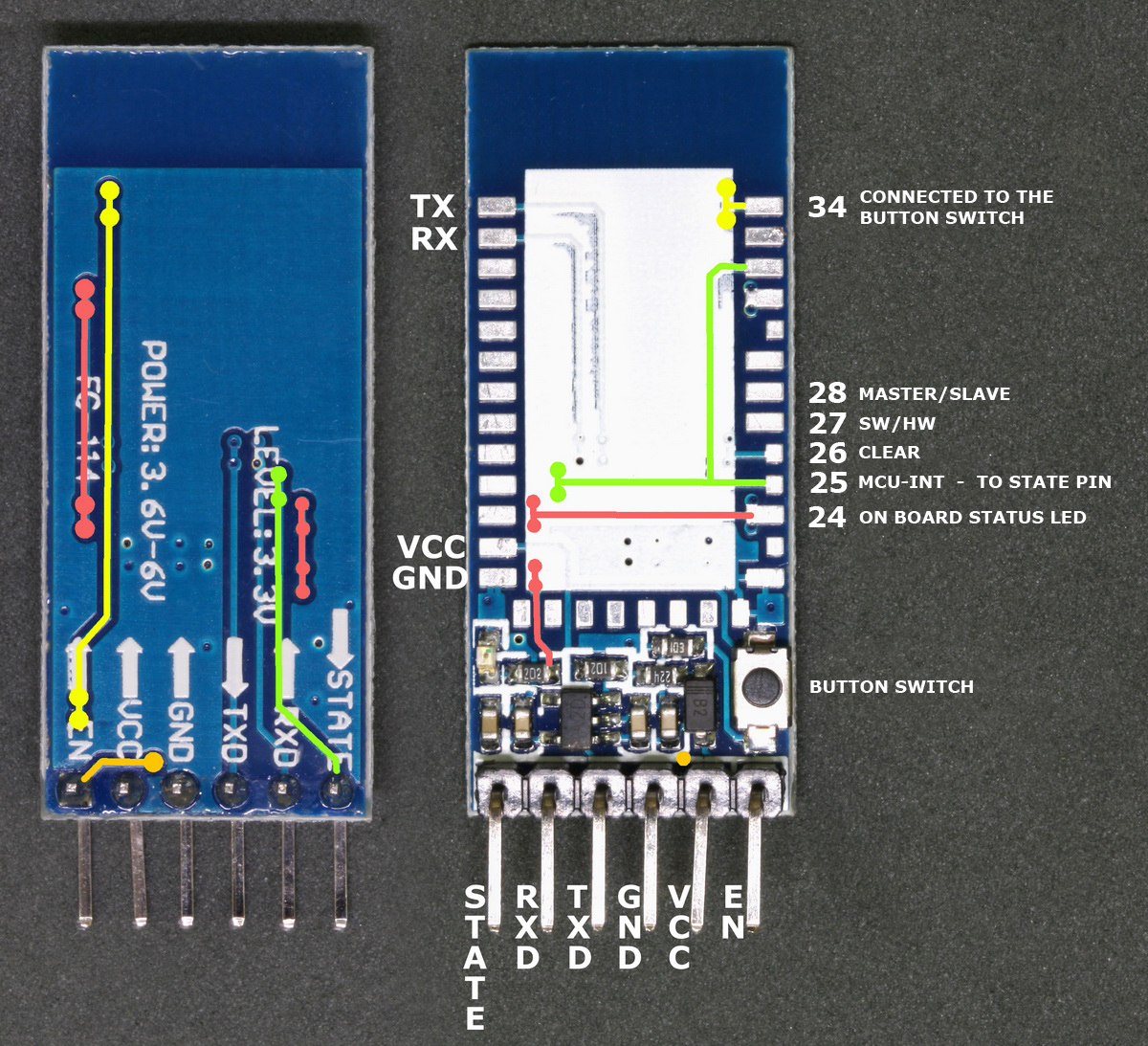
I have just received some new HC-05 and HC-06 Bluetooth modules. These were sold as zs-040s which is the module I actually wanted but I received modules marked FC-114. They share the same breakout board as the zs-040 but have different pins soldered between the Bluetooth module and the breakout board and have a very different firmware.
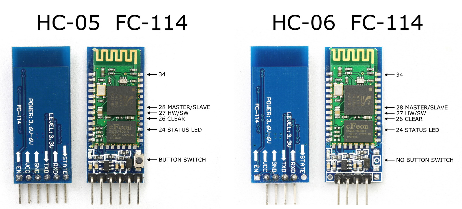
The small push button switch still has traces to pin 34 and still pulls pin 34 HIGH, however, on the FC-114 boards, pin 34 is a regular IO pin and closing the button switch doesn’t do anything. On the zs-040 boards, closing the button switch and pulling pin 34 HIGH puts the modules in to AT mode. Since the FC-114 starts in AT mode this is no big loss.
It took me a while to figure out the differences.
When powered on, the modules report themselves as “AEGIN” and default to Slave Mode with a baud rate of 9600. The process for using them in Slave Mode, connecting to the Arduino and talking to an Android device, is the same as other modules.
Like other HC-05s and HC-06s the boards have a voltage regular on the vcc pin and accept a voltage in of 3.6v to 6V, however, the other pins are 3.3v only. This means you can power the boards from a 5V rail using the vcc in but you should not connect the others pins directly to 5V.
HC-05 FC-114
I assumed these were like other HC-05s I had but could not find how to get in to AT mode. By accident I reset the module while the serial monitor was open and received a start up message.
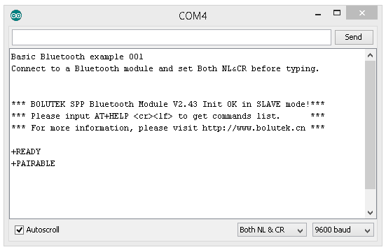
This shows the manufactures website, that the modules are in Slave Mode and that they have a “AT+HELP” command.
A quick “AT+HELP” later I had a list of the AT commands.
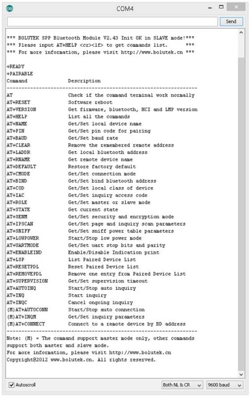
This means the modules do not have a separate AT mode like other HC-05s. On start up they are in Slave Mode and accepting commands. After a connection is made the modules go in to communication mode and AT commands no longer work. In communication mode anything the module receives is treated as data and sent to the connected device.
“AT+VERSION” returns the firmware version number which reports as:
+BOLUTEK Firmware V2.43, Bluetooth V2.0, HCI V2.1, HCI Rev37, LMP V4, LMP SubV37
HC-06 FC-114
The HC-06s use the same breakout board as the HC-05s but have some differences.
– there is no button switch
– there is no connector on the EN pin
– there is no connector on the STATE pin
EN Pin
When the EN pin is pulled LOW (connected to ground) the modules are disabled.
STATE Pin
The STATE pin on the breakout boards connects to pin 25 and pin 32 on the small Bluetooth module. On the FC-114 pin 32 in a normal IO pin and pin 25 is MCU_INT. On the boards I received pin 25 was not connected to the breakout board and so the STATE pin was not connected. After connecting pin 25 to the breakout board the STATE pin works as expected; LOW when not connected and HIGH when connected.
Tt appears that the HC-06 FC-114s have the same firmware as the HC-05 FC-114s. “AT+HELP” gives the same list of AT commands and “AT+VERSION” reports the same firmware version: “+BOLUTEK Firmware V2.43, Bluetooth V2.0, HCI V2.1, HCI Rev37, LMP V4, LMP SubV37” and should mean that HC-06s can be used as Master devices.
BLK-MD-BC04-B
The manufacturers website gave me the model number of the Bluetooth modules.
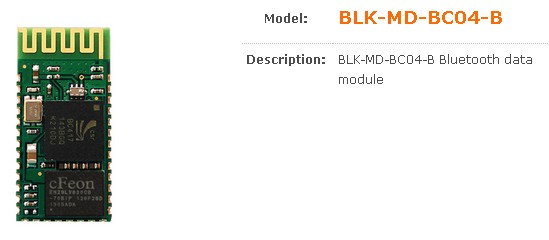
A visit to http://www.bolutek.cn shows that the Bluetooth daughter boards are model BLK-MD-BC04-B.
And from the manufacturers website we find that:
The BLK-MD-BC04-B is a Bluetooth serial module for OEM manufacturers who want to implement Bluetooth functionality with their products cost effectively and also in timely manner. The BC04-B supports UART, USB, I2C, PCM, PIO interfaces for the communication with the OEM products.
The BC04-B is provided with Bluetooth v2.0 compatible firmware runs internally for SPP (Serial Port Profile) applications by default. It based on CSR BC04 External chipset with an antenna integrated and with the firmware provided by our company, it could be easily used for kinds of Bluetooth products.
The BC04-B is fully qualified with Bluetooth v.2.0+EDR specification so OEM manufacturers can save cost and time for overall OEM product certifications, which makes the BC04-B ideal solution for larger volume and cost sensitive applications.
Specifications:
Bluetooth protocol: Bluetooth Specification v2.0 + EDR
USB protocol: USB v1.1/2.0
Frequency: 2.4GHz ISM band
Modulation: GFSK (Gaussian Frequency Shift Keying)
Transmit power: ≤ 4dBm, Class 2
Sensitivity: ≤-84dBm at 0.1% BER
Rate: 2.1Mbps(Max)/160 kbps(Asynchronous);1Mbps/1Mbps(Synchronous)
security features: Authentication and encryption
Support profiles: Bluetooth serial port (master & slave)
Power Supply: +3.3 VDC 50mA
Operating temperature: -20 ~ +55 Centigrade
Dimensions: 26.9mm x 13mm x 2.2 mm
One thing to note is the power consumption; 3.3v at 50mA. I do not know if 50mA is constant or if it is the maximum the board can draw (likely it is the maximum) and this too much for a regular Arduino pin to supply so the modules should not be connected to a regular Arduino pin.
They can safely be powered from the Arduinos 5V out but it is worth remembering that the 5V pin on can only supply up to to 200mA so if you are adding other devices/sensors you may need to be careful of the total current.
Once I had the model number it was fairly easy to get more information online and means these are not new modules, just new to me. It may be that they have not been put on to these breakout boards before though.
BLK-MD-BC04-B Pins
Although the small modules look the same as the ones used in other HC-05s and HC-06s the Bolutek firmware uses different pins.
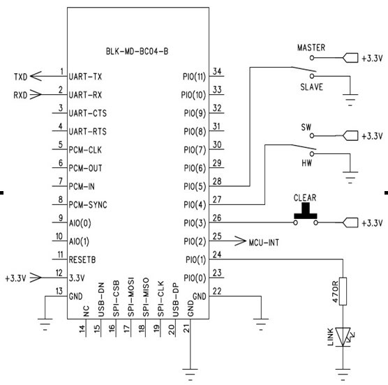
From this we can see that
– Pin 24 is for a status LED. This is connected to the LED on the breakout board.
– Pin 26 is reset. This is not connected.
– Pin 27 is used to determine if Master Mode can be selected in software or Hardware.
– Pin 28 is used to select Master or Slave through hardware.
Pin 26 reset:
– short press = memory clear
– Long press (3 seconds+) = restore default settings
If pin 27 is HIGH then we can set Master Mode in software. If pin 27 is LOW then we need to use hardware (pin 28) to select Master Mode.
When pin 27 is LOW (or not connected) pin 28 is used to selected either Slave Mode or Master Mode.
– Pin 27 LOW + pin 28 LOW = Slave Mode.
– Pin 27 LOW + pin 28 HIGH = Master Mode.
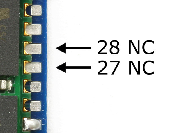
On the modules I have, pin 27 and pin 28 are not connected. This means, at least at the moment, I cannot set the modules to Master Mode in software. Trying to change to Master Mode using “AT+ROLE1” gives me an OK but it does not seem to actual put the modules in to Master Mode. However, it is early days and I haven’t really experimented with these modules yet.
I need to research this further but it it likely that if I want to use these modules in Master Mode I will need to solder wires to pins 27 and 28.
Updated 10.08.2015.
I ended up putting a wire on to pin 27. See HC-05 FC-114 and HC-06 FC-114. Part 3 – Master Mode and Auto Connect
Downloads
BLK-MD-BC04-B BLUETOOTH MODULE AT COMMANDS
BLK-MD-BC04-B_DEMO_schematic
Links
Bolutek’s website
Looks like Bolutek moved their website to and went up market. Now at http://www.bolutek.com/en/
Im so BLUEtooth today
Electrodragon
BC04 manual from Electrodragon
Next
Part 2: Basic AT commands
Part 3: Master mode and auto connect
Hi, need your help. Is it possible to us FC-114 with HM-10 module ?
The HM-10 modules are Bluetooth V4 only and so cannot connect to the FC-144 modules.
Hi, I have FC-114 HC-06 module, but I can not put it in AT MODE, the LED module is always blinking fast. How do I get it? I’m using an arduino UNO. Please let me know if you need some other clues.
thanks.
HC-06s are in At mode by default, however, you may not have the Bolutek firmware.
Using the set up / connections from https://www.martyncurrey.com/hc-05-fc-114-and-hc-06-fc-114-part-2-basic-at-commands/ do you get the welcome message when you cycle the power to the HC-06?
Does AT+HELP give you a list of commands?
If no to both questions you likely have a different firmware. Have a look at https://www.martyncurrey.com/arduino-and-hc-06-zs-040/.
Try different baud rates and different line end settings.
Start with the basic AT command which should reply with “OK”
1 – try 9600 and “No line ending”, if this does no work, try
2 – 9600 with “Both NL & CR”
If 1 & 2 do not work try 38400.
Once you get AT working find out what firmware you have with AT+VERSION
Hi, My new HC-06 doesn’t even blink in my Arduino Mega2560.
My question is : does the Rx needs exactly 3.3 V to work ? because i have only a 1.8 ohm resistor ?
When the LED Blink ?
thank you.
The LED should blink as soon as you apply power. Are you using 5V connected to the vcc pin on the breakout board?
It appears not all FC-114 boards use the same firmware and you may have different LED blinks/status. You need to try and confirm which firmware you have.
Use the set up from https://www.martyncurrey.com/hc-05-fc-114-and-hc-06-fc-114-part-2-basic-at-commands/. While connected to the Arduino and with the serial monitor open, cycle the power to the HC-06 and see what welcome message you get.
With a 1.8K resistor instead of a 2K resistor you will you have 3.2V (if I have done the calc correctly) instead of 3.3v. This should be fine.
I tried it but to use.
Every time i enter “AT”, it echoed “Qõ/ÿ”.
the baud rate you chose rate is not the good one
hi!
i really need your help with hc-05 fc-114 i don’t have wires to set pin 27 and 28 directly(hawdware method) can you help me with a software solution to configure my hc-05 fc-114 to AT mode ??
The modules I have are already in AT mode. Do you mean Master Mode?
The modules need a connection to pin 27 or pin 28 to enter Master Mode.
Hi. Great information, thanks for sharing.
I have HC06-114 labeled ZS-040. I can send AT commands from PC Serial Monitor and have all responses opk. I can chnage NAME and i see versión. But i can not connect from the Android. I can see the Arduino from the APP but never connects. Say the PIN is incorrect.
If i check AT+PIN, the result is PIN=000000 (6 numbers). I can change for other 6 different numbers, but maybe the reason for can not connect be that.
Can you help me?
Thank you in advance and excuse my english…
Javier
Unfortunately there are now many different Bluetooth modules that use the same zs-040 breakout board and if the PIN is 6 digits then it is using a different firmware to the ones above. What firmware version do you have?
Hello again. This is what i have with AT+VERSION is:
+VERSION=Firmware V3.0.6,Bluetooth V4.0 LE
Thanks for your response.
Javier
It looks like you have the AT-09/HM10 BLE device.
If the same as the ones I have it:
has the CC2541 chip,
identifies itself as BT05
is Bluetooth v4 only
Some Android devices can see the module in the settings, other cannot. Either way use a Bluetooth 4/BLE terminal app to connect. Even if the Android modules don’t show the BT05 in the settings most will connect when using a BLE compatible app. See https://www.martyncurrey.com/bluetooth-modules/
OK. It is like the photo but with only four pins… and does not work with Android…
Thank you.
Hi,
I’m using a PIC microcontroller and able to communicate with a USB to RS-232 to the PC using putty. Then when I switch to the FC-114, no communication at all.
So, upon start up the FC-114 is in AT mode?
Above it says,
” …..After a connection is made the modules go in to communication mode and AT commands no longer work. In communication mode anything the module receives is treated as data and sent to the connected device.”
Question: Does communication mode mean pairing established?
My baud rate is 9600, Flow control off, 8 bits, 1 stop bit
I’m able to establish pairing, but no communication from microcontroller.
Is the FC-114 in AT mode or communication mode after pairing?
Thanks for all your help.
Randy
After pairing the device is still in AT mode and you then need to start communication. Have a look at https://www.martyncurrey.com/hc-05-fc-114-and-hc-06-fc-114-part-3-master-mode-and-auto-connect/ for a basic way to connect 2 modules.
You can also follow the examples in the https://www.martyncurrey.com/arduino-and-hc-06-zs-040/ post to talk to an Android device.
Hi,
This is really nicely written article. Thanks
However, I request Martyn to change the manufacturer’s website link to
http://www.bolutek.cn/Products_info.asp?id=278 instead of http://www.bolutek.com
Thanks again! :)
I’ve updated the link. Didn’t realize the .com website link was broken. It looks like they have revamped their main site.
hi all,
i use ARDUINO UNO with fc-114 module and when i open serial monitor at 9600
it responds “Enter AT commands:”
and 38400 “xxxxxxxxxxxxxxxxxxxxxxx”
what shall i do pls!!!
#Martyn
Hello Martyn, It seems like i have an HC-06 FC-144, as this is what is written on the Module and it also shows up as HC-06 on my Computer when i go to Bluetooth settings. I was trying to get it into AT mode, because i have to change the baud rate to 115200 because i need it to communicate MIDI messages to my Computer. No mentioned Method worked for me getting it to respond to AT Commands, i didn´t even get it to say ok to a simple AT. I wired it on my arduino Mega, with VCC to 5V, GND to GND, RX over Voltage divider (1K, 2K) to TX on Arduino, and Tx to RX. I paired with it before with my computer just to see if that worked, and now i can´t even pair with it anymore. its just blinking along and doesn´t respond to anything i´m doing. I´m really desperate cause i spend days trying to figure out what I can do to change its baud rate… i hope you can help. Thanks a lot.
Hello Master Martyn.
I have HC-05 ( I can only understand it is HC-05 because it has a button over it, and the shop I bought it sold it as HC-05 ) I uploaded your code and that worked fine with my android phone. But I cannot use AT commants.
Any AT command never responds back. I tried the holding the button, It didnt help. PS: Pin34 is soldered and FC-114 is not printed on it. Nothing is printed except pinouts.
Good Paige for HCO5 designer. My problem is that AT commands stop responding suddenly.. looks like others had same problem also..