Updated: 30.10.2017
The old guide was out of date and had become a little messy and I had been thinking about redoing it for a while. Also, how I use the ESP8266 has changed and since I am using one as part of a IOT Word Clock I am currently building I thought I would update the guide. So, here is the all new version 2.0. The post for the IOT Word Clock will come later, probably much later…
Part 1: The Esp8266 and setting up the Arduino IDE
Part 2: Control an LED from a web page using Access Point Mode (AP)
Part 3: Control an LED from a web page using Access Station Mode (ST)
Part 4: mDNS
Part 5: wifiManager
Part 6: JavaScript and AJAX
Part 7: More Controls. 3 LEDs
Part 8: Auto Updating Webpage
Part 9: First steps with Websockets
Part 10a: IOT Monitor part 1 – webpage
Part 10b: IOT Monitor part 2 – enhancing the webpage
Part 10c: IOT Monitor part 3 – adding a LCD
Part 10d: IOT Monitor part 4 – the final project
When the ESP8266 first came out there was a lot of excitement and buzz. Here was a new chip that was cheap and allowed internet connectivity. I got caught up in all the excitement and bought several different modules. I intended to use them in various projects where I wanted some kind of remote control. Things didn’t go as planned though, I found the AT command interface very clunky and the ESp8266’s not very reliable. I put the ESP8266s away in the bottom of a draw and moved to Bluetooth.
Things changed when the ESP8266 core for the Arduino IDE was released. This meant you could program them as if they were Arduinos, no more messing around with AT commands. Programming the ESP8266s via the Arduino IDE made things a lot easier and it meant that in many cases you no longer required an Arduino.
ESP8266 Basic Specs
By now everybody should know that the ESP8266 is, in essence, a small microprocessor with built in wi-fi. It is faster than most Arduinos and has more memory than most Arduinos and has less pins than an Arduino.
- 32-bit RISC CPU: Tensilica Xtensa L106 running at 80 MHz
- 64 KiB of instruction RAM, 96 KiB of data RAM
- External QSPI flash: 512 KiB to 4 MiB (up to 16 MiB is supported)
- IEEE 802.11 b/g/n Wi-Fi
- Integrated TR switch, balun, LNA, power amplifier and matching network
- WEP or WPA/WPA2 authentication, or open networks
- 16 GPIO pins
- SPI
- I²C
- I²S interfaces with DMA (sharing pins with GPIO)
- UART on dedicated pins, plus a transmit-only UART can be enabled on GPIO2
- 10-bit ADC (this is a Successive Approximation ADC)
For small projects that require web connection it can replace an Arduino but for other projects it can be used to complement an Arduino perfectly and this is how I mostly use them. I offload the web part of a project to the ESP8266 and use an Arduino, usually a Nano, as the main microprocessor. The two talk to each other using serial.
Adding the ESP8266 core to the Arduino IDE
First things first. You can’t use the Arduino IDE until you have added the ESP8266 core. I presume you have the Arduino IDE either installed, or like me, are using the non installed folder version. In this example I am using IDE version 1.8.3. At the time of writing this is the latest.
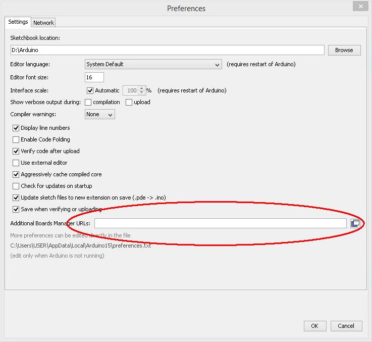
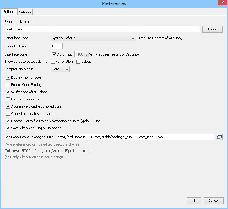
Open the preferences, and enter the following address in to the Additional Board Manager URLs field.
http://arduino.esp8266.com/stable/package_esp8266com_index.json
You can enter multiple URLs, you just need to separate them with commas.
For more information about the ESP8266 core visit the projects GitHub page.
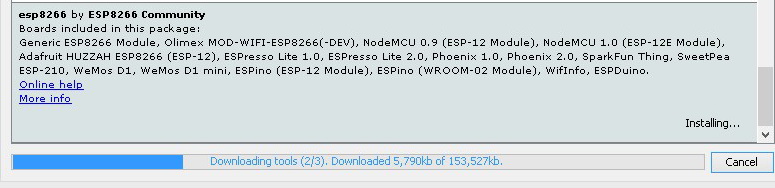
After entering the ESP8266 url, open up the board manager window and scroll down to the ESP8266 entry (usually at the bottom).
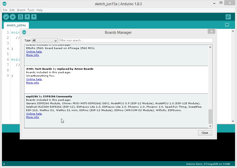
Select the ESP8266 entry. When you click it an install option will appear
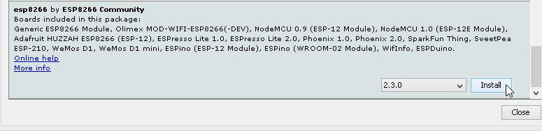
Select the latest version and click install.
After the installation has finished, go to the boards section and you should now have a whole list of different ESP8266 modules to chose from.
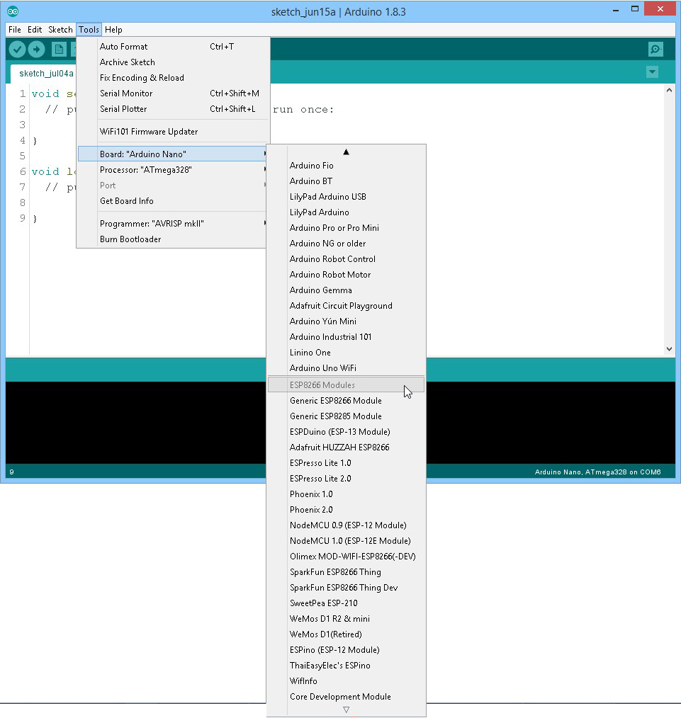
The selected board appears at the bottom of the IDE. Here I am using a NodeMCU V0.9 board.
![]()
ESP8266 development Boards
There are now many different development boards and for a while it seemed everybody and their dog was creating a new one. I have more-or-less settled on the NodeMCU boards for general development or my own programming board.
To program the ESP8266-01 I built a programming board. This works well but requires a usb-to-serial adapter.
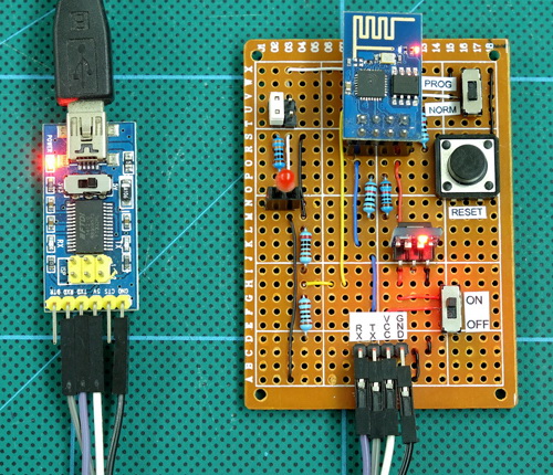
For more details see the ESP8266-01 Programming Breakout Board post.
For normal development I generally use a NodeMCU 0.9 board. Having the usb built in makes these very convenient to use. When these first came out I bought a few and I am still working my way through them. Should I need to buy more I will get the V1.0 or what ever the latest version is at the time.
I use the NodeMCU boards like an Arduino and program them through the Arduino IDE not Lua. When development is done I upload the finished code to what ever ESP8266 module I am using in the project (normally an ESP8266-01).
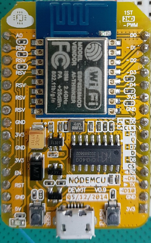 The NodeMCU boards have USB built in and this makes them easy and convenient to use, just connect them to a computer the same as a typical Arduino. Remember the pins are still 3.3v only though.
There is now a 1.0 version which is what I recommend. These have more memory and they fit breadboards better. The 0.9 version fits on to a breadboard but it covers all the holes so you cannot make any connections unless you have it hanging from one side like I do, see the photo below.
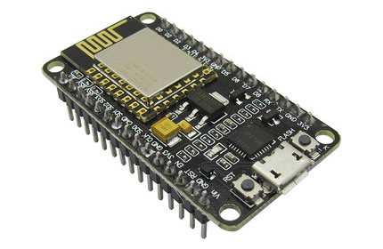 The NodeMCU v1.0 board is slightly slimmer than the v0.9 version so it fits a bread board better. You should also notice the colour of the small ESP8266 daughter board is black rather than blue. This (normally) means the ESP8266 module is using the ESP-12E rather than the ESP-12 chip.
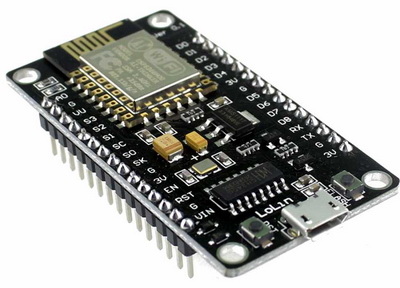 I also have a couple of the Lolin 3.0 boards which I have had lots of trouble with and recommend you do not buy.
NodeMCU Boards
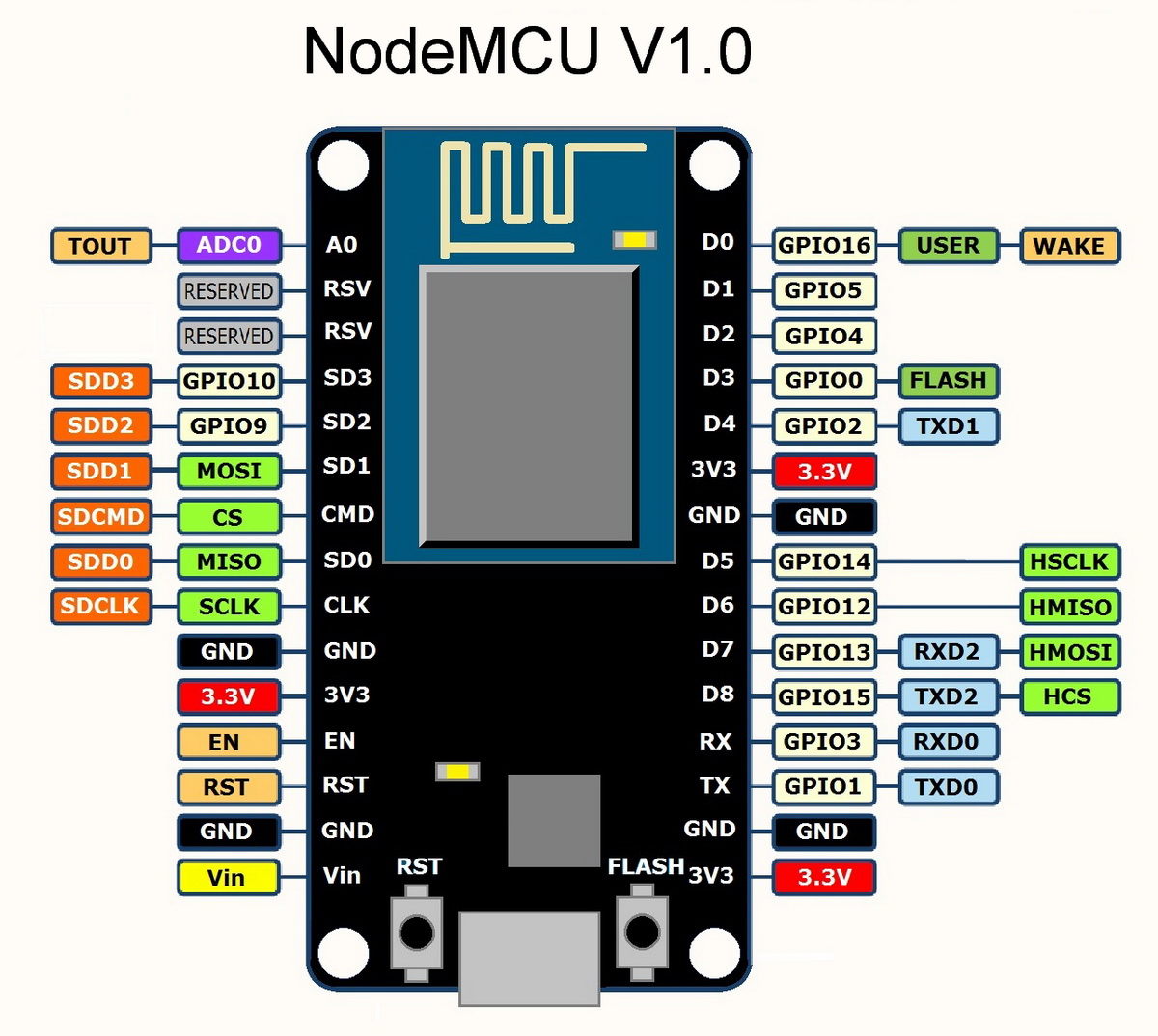
The NodeMCU project is a package of hardware and software and the NodeMCU boards were originally intended to run the LUA language programming language. Conveniently, the boards can be used with the Arduino IDE and be programmed just like another Arduino. When programmed through the Arduino IDE you can think of the NodeMCU board as if it were an Arduino with slightly fewer pins and wifi built in. One thing to note though, is the pin mapping. This is a little different to an Arduino. With the NodeMCU board there are two sets of pin definitions; the ESP8266s GPIO pins and the boards D pins.
If you use a pin number such as:
int LED_Pin = 1; |
you refer to the GPIO pin and this is not the same as the D pins labelled on the boards. To reference the pin numbers on the boards you have to use D1:
int LED_Pin = D1; |
The below shows the pin mapping for the v0.9 board. Image courtesy of www.cnx-software.com.
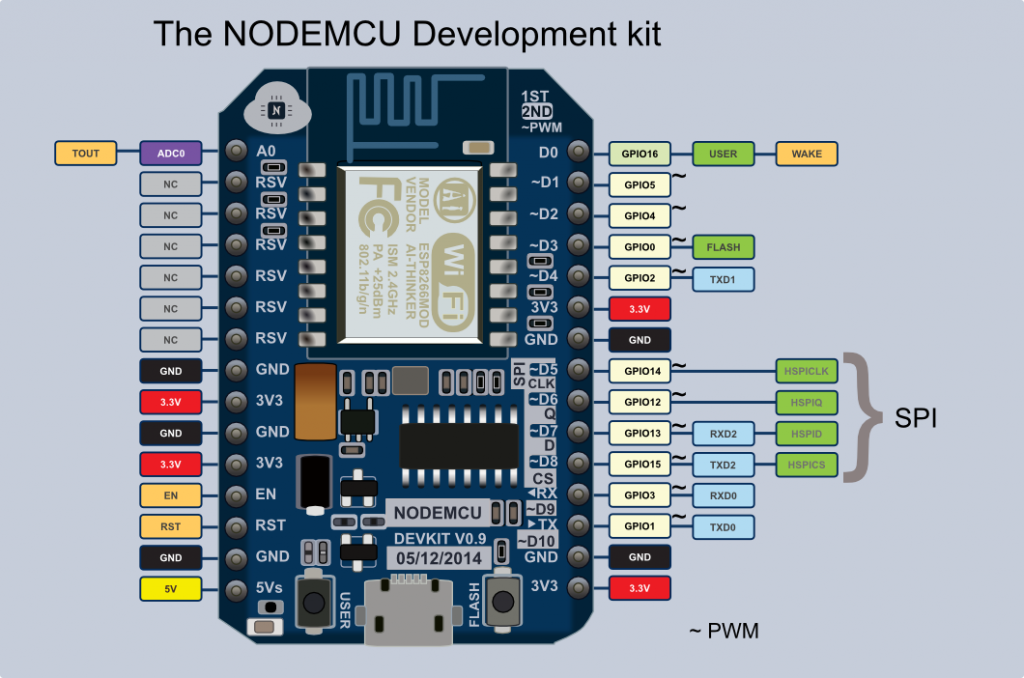
NodeMCU 0.9 Pin Mapping
| PIN | GPIO | PIN | GPIO | |
| D0 | 16 | D6 | 12 | |
| D1 | 5 | D7 | 13 | |
| D2 | 4 | D8 | 15 | |
| D3 | 0 | D9 | 3 | |
| D4 | 2 | D10 | 1 | |
| D5 | 14 |
NodeMCU v1.0 Pin Mapping
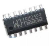 The NodeMCU boards use the CH340 serial adaptor chip and if this is the first time you have used it you will need a driver. The driver (all OSs) can be downloaded from the manufacturers website here or the Windows driver can be downloaded from this website here.
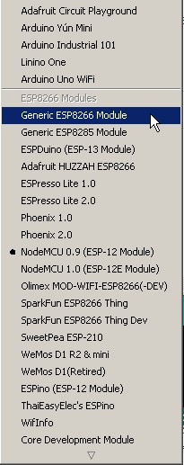 Remember to select the board you are using in the Arduino IDE. If you are using the ESP8266-01, for example, you need to select “Generic ESP8266 Module”.
ESP8266 Sketch 1: Blink an LED
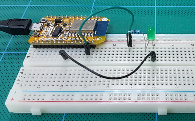
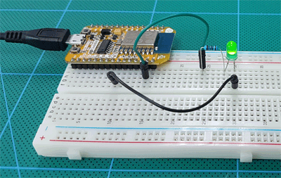
As a first step let’s blink an LED. This may seem very basic but it ensures everything is working as it should be. I am using the NodeMCU 0.9 board but any similar board will work the same.
Connect an LED and resistor to pin D2. Remember the ESP8266 is a 3.3v device so a smallish resistor is required. LEDs generally have a forward voltage drop of 2v-3v depending on the colour. Assuming our LED has a forward voltage drop of 2V and uses 20mA ( 0.02A ) we can calculate (using ohm’s law) the value of the resistor required.
R = supply voltage – voltage drop (Vs – Vf) / Current required (I)
R = (3.3 – 2) / 0.02
R = 65
So I need a 65 ohm resistor, I don’t have any so I am using 100 ohm. When selecting a resistor, slightly larger is OK but a smaller one is not. The larger the resistor the dimmer the LED will appear.
Circuit
Very simple circuit. and LED and a resistor in series connected to D1.
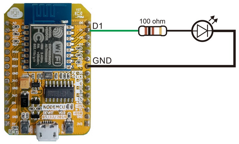
ESP8266 Sketch 1: Blink an LED
This is basically the blink example from the Arduino IDE. All I have done is change the pin. Upload the sketch and if everything is fine the LED should blink on and off once a second.
/* ESP8266 Blink Blink an LED connected to pin D1 */ // ModeMCU pin mapping is a little weird so use D0, D1,D3 rather than 1,2,3 // pin 1,2,3 refers to the GPIO pins int LED_Pin = D1; void setup() { pinMode(LED_Pin, OUTPUT); } void loop() { digitalWrite(LED_Pin, LOW); delay(1000); digitalWrite(LED_Pin, HIGH); delay(1000); } |
If you have everything correct the LED should blink on/off once a second.
Problems Uploading
If you get errors when trying to upload, such as:
warning: espcomm_sync failed error: espcomm_open failed error: espcomm_upload_mem failed error: espcomm_upload_mem failed |
Itr is likely that the ESP8266 module is not resetting or is not in upload mode. This often happens when you have selected the wrong board in the IDE.
ESP8266 Downloads
CH340/341 drivers all OSes manufacturers site.
CH340 driver for Windows from this website..
This helped me a lot
Thank you
Currently the best guide I have read about NodeMCU as WebServer using Arduino.
Notting but brilliant
How are you powering the NodeMCU board?
I see a USB cord.
Are you simply using the PC’s USB port?
yes.
Nice write up (as always) Martyn, thanks. Looking forward to working through them all. I got a wide board which is soooo annoying, but cobbled together 2 small breadboards on a bit of wood and have the NodeMcu plugged into both.
Couple of minor points though, if I may:
“Assuming our LED has a forward voltage drop of 2V and uses 0.2mA ( 0.02A ) we can calculate ” should be “uses 20mA ( 0.02A ) ”
“R = 3.3 – 2 / 0.02” needs brackets: “R = (3.3 – 2) / 0.02”
Cheers,
Jim
Hi Jim,
thanks for spotting the mistakes. Have corrected the post.
Congratulations for the work, it’s helping me a lot, thanks.
http://alvieletronica.blogspot.com
now esp8266wifi.h is not available through github. (try it). So how to install esp8266 board on arduino uno.
It is now part of the ESP8266 core.