Just started to play with the ESP8266-01 modules. Purchased from Taobao.
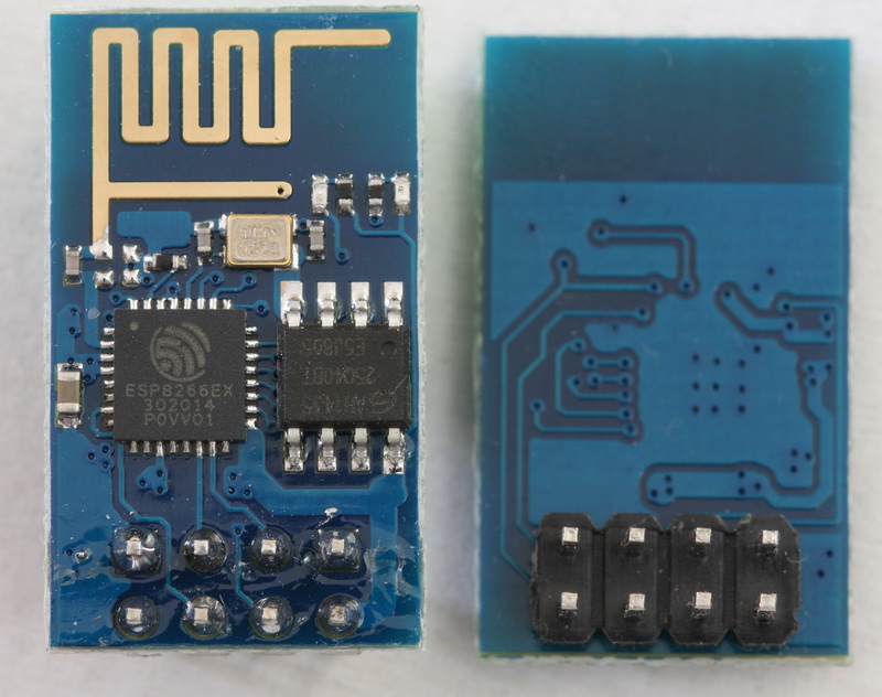
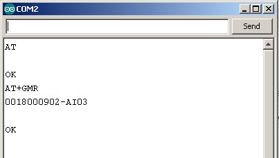
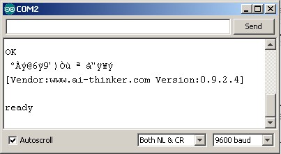
These, I believe, are version 2 and have the LEDs near the antenna. When first started they identify themselves as [Vendor:www.ai-thinker.com Version:0.9.2.4] and are version 018000902-AI03. This is a custom firmware from ai-thinker.
There seems to be quite a few different versions of similar modules. And the same module could have one of several firmwares.
Initially had trouble getting them to work. A lot of the guides online are a bit sparse and many have conflicting information. Most current guides say the baud rate is 115200 or 57600 (mine are 9600) and they fail to mention you need to pull CH_PD HIGH (10K resistor to 3.3V). This meant I went through a lot of trial and error.
Default Settings
The defaults for the devices I purchased are:
– ID = [Vendor:www.ai-thinker.com Version:0.9.2.4]
– Software version = 0018000902-AI03
– SSID = ESP_xxxxx (will be a hexadecimal number)
– CWMODE =2 (functions as an access point and therefore broadcasts on start)
– Baud rate 9600
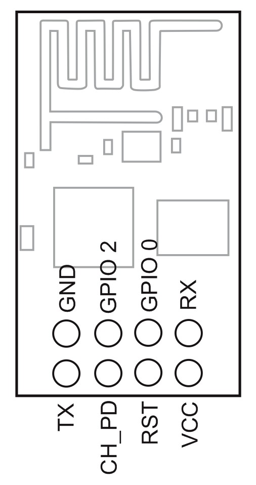
Pins
Connections
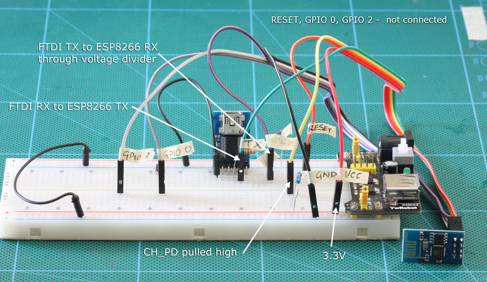
I have used an Arduino and also an FTDI serial adaptor to talk to the ESP8266. Both worked the same. For details on connecting an Arduino see Arduino to ESP8266 By Serial Communication. Sending commands is the same for both methods.
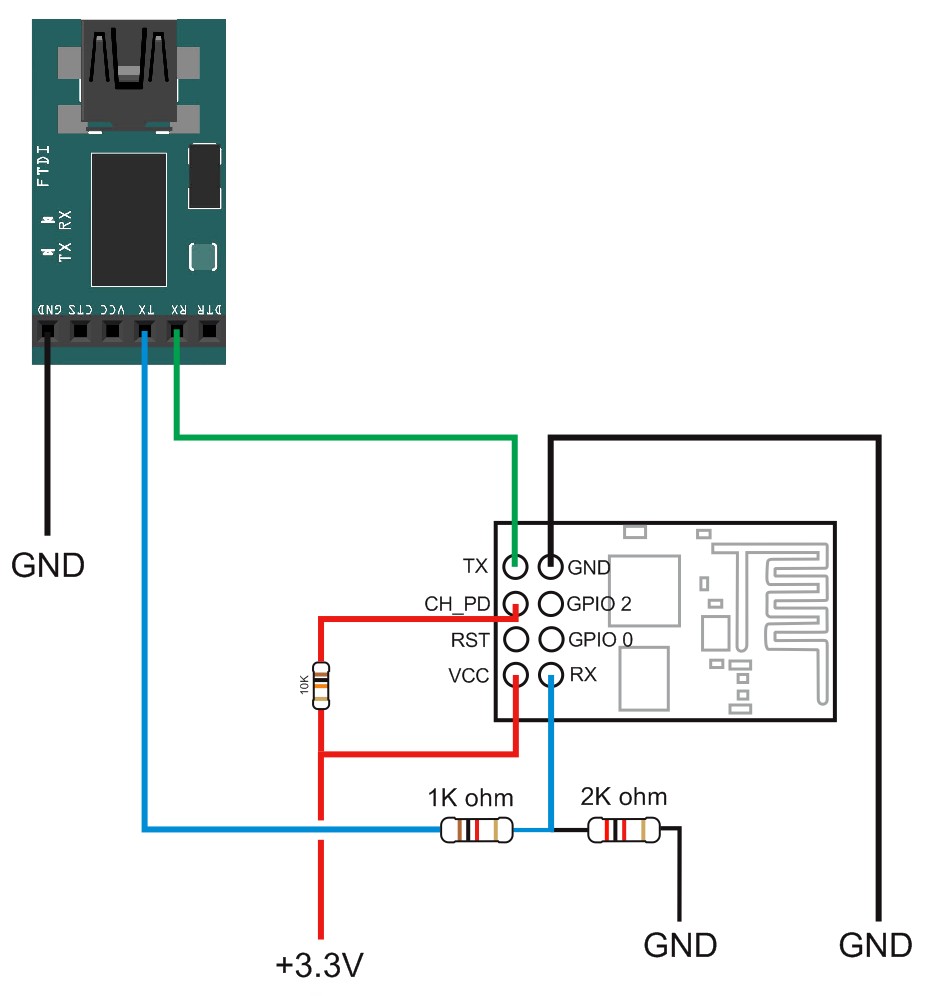
FTDI RX to ESP8266 TX
FTDI TX to voltage divider then to ESP8266 RX
FTDI GND to GND
FTDI CP_PD to 10K ohm resistor and then to vcc 3.3v
ESP8266 GND to GND
ESP8266 Vcc to +3.3V
FTDI TX is 5V which needs bringing down to 3.3v. This is done with a voltage divider.
FTDI RX can be connected to ESP8266 TX directly. The FTDI will accept the 3.3v signal from the ESP8266 as HIGH.
A lot of people are using the 3.3v out on the Arduino to power the ESP8266 but the Arduino cannot really provide enough power and may damage something. I have a habit of destroying things and I now try to be more careful and since I have a breadboard power supply that can give 3.3v I am using it.
Plug the FTDI adaptor in to a usb port on your computer and power up the ESP8266. The power LED on the ESP8266 should come on.
To check if there is a signal I used the Android app Wifi Analyzer, available here. This app scans all available wireless networks and displays their signal strength.
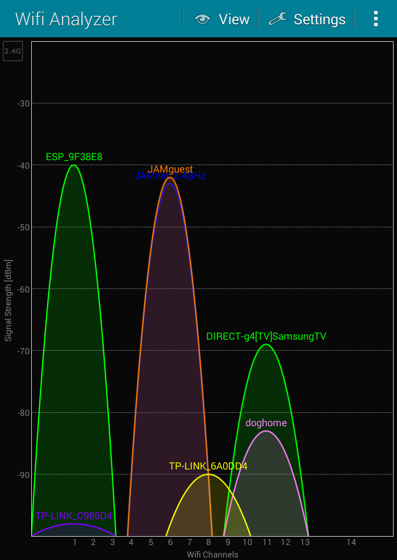
It should show up as ESP_xxxxxx. If it doesn’t then check your connections and restart.
Serial Communication With The ESP8266
Once you have confirmed it is working and transmiting you can try to connect by serial. There are many serial terminal programs and one of the easiest ways is to use the serial monitor in the Arduino IDE. Fire up the IDE, select the com port and open the serial monitor.
At the bottom of the window select 9600 baud rate and also “Both NL & CR”. This adds a new line and carriage return to what ever you enter. The ESP8266 needs these characters.

Now enter AT and hit send and hopefully you should receive an “OK”. If you do not then try all the different baud rates.
The AT command is a simple test to confirm the ESP8266 is communicating. There are many more commands which are used to interrogate the chip and to make changes to the settings.
To find out what firmware version you have enter AT+GMR
AT+RST resets the chip. On restart the chip will identify itself
Join a Network
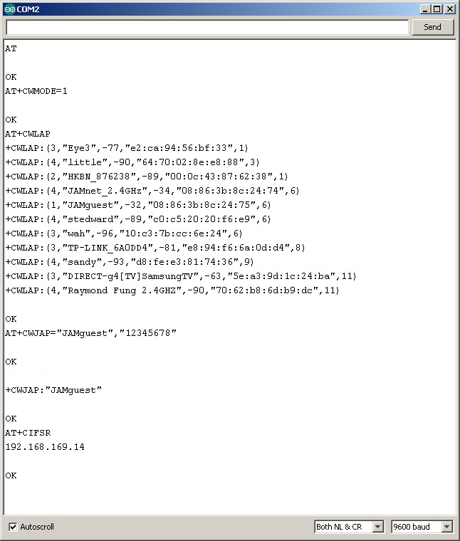
AT – Confirm that the esp8266 is communicating.
Response is OK
AT+CWMODE=1 – Set the chip to a client (you can also set as an access point or both)
Response should be OK.
AT+CWLAP – List available networks
Response will be a list of local networks:
+CWLAP:(3,"Eye3",-77,"e2:ca:94:56:bf:33",1)
+CWLAP:(4,"little",-90,"64:70:02:8e:e8:88",3)
+CWLAP:(2,"HKBN_876238",-89,"00:0c:43:87:62:38",1)
+CWLAP:(4,"JAMnet_2.4GHz",-34,"08:86:3b:8c:24:74",6)
+CWLAP:(1,"JAMguest",-32,"08:86:3b:8c:24:75",6)
+CWLAP:(4,"stedward",-89,"c0:c5:20:20:f6:e9",6)
+CWLAP:(3,"wah",-96,"10:c3:7b:cc:6e:24",6)
+CWLAP:(3,"TP-LINK_6A0DD4",-81,"e8:94:f6:6a:0d:d4",8)
+CWLAP:(4,"sandy",-93,"d8:fe:e3:81:74:36",9)
+CWLAP:(3,"DIRECT-g4[TV]SamsungTV",-63,"5e:a3:9d:1c:24:ba",11)
+CWLAP:(4,"Raymond Fung 2.4GHZ",-90,"70:62:b8:6d:b9:dc",11)
AT+CWJAP – Join a network
AT+CWJAP=”ssid”,”password” – use your own SSID and password
AT+CWJAP=”JAMguest”,”12345678″
Response is OK
AT+CWJAP? – Check the name of the connected network.
Should give you the SSID , in my case it returns +CWJAP:”JAMguest”
AT+CIFSR – Check the ip address of the chip
Replies with the ip address. I got 192.168.169.14
This is the ip address assigned by your router
A list of AT commands, as well as a lot of other information, can be found on the Electrodragon site
The unofficial ESP8266 site is http://www.esp8266.com
Trouble Shooting
Set CP_PD to HIGH. Without this the unit will power on but will not broadcast a signal.
Try to get it broadcasting a signal before you try connecting with a serial terminal.
However, if it is not broadcasting you may need to change the mode to AP (AT+CWMODE=2).
If you cannot talk to it (over serial), try different baud rates. Not all modules have the same baud rate as default. Mine were 9600 but 115200 is also common.
Remember it expects to have newlines and carriage returns (NL&CR) on the end of the commands.
Very helpful! Especially the 10k resistor on CH_PD and the Android tool. Mine had the same firmware level.
Now on to nodeMCU with MQTT…
WiFi Analyzer and NL+CR were crucial to me.
How to do if no FTDI adaptor?
Take a look at https://www.martyncurrey.com/arduino-to-esp8266-serial-commincation which uses an Arduino rather than an FTDI adaptor.
Hi, the FTDI in your picture is looks the same i have…
Can you use the solderbridge on the back to set it to 3.3V and forget about the voltage divider resistors?
Yes you can. Just make sure you don’t join the 5V pad….
It would be a good idea to check the voltages to make sure it is 3.3v before using it.
Here is a close up photo of the module I used for the above example https://d3s5r33r268y59.cloudfront.net/5132/products/thumbs/2014-06-24T01:17:19.246Z-uart_hi_res.jpg.2560x2560_q85.jpg
This shows the solders pads very clearly.
I also have some adaptors that have a physical switch. These are more convenient to use.
Obviously not quite THE site i need, but It’s nearest I’ve found after a month of intermittent searching, so here goes.
On a whim I purchased a NODEMCU DEVKIT V0.9 a few months ago.
It pops up on 2.4GHz as AI-THINKER_9B1D01 on channel 1.
and that is as fare as I can get, ‘cos I can’t find any further info.
It has a micro USB socket, and I use that the power it.
Can you point me in a sourc of further information please – pretty please.
TIA
MickyB
I haven’t used the ESP8266 modules for a while and never with Lua or nodemcu, however, there is help on the internet. Rather than searching for the board you should search for nodemcu.
http://www.guillier.org/blog/tag/esp8266.html may be a good place to start.
my esp had i think node mcu software. i tried to interrogate it with the serial monitor and various commands at, at+rst all in uppercase with various baude rate settings. but all that came out was gobadaldy gook . any ideas please
regards
jh
I can’t personally help but have a look at http://www.guillier.org/blog/tag/esp8266.html and the esp8266 forum http://www.esp8266.com/viewforum.php?f=17
Hi
I am connecting the ESP8266 01 module to FDTI and to computer in the same way. My ESP is getting reset again and again printing garbage ▒RS▒fJ[▒fJ[▒fJ▒▒vf▒fV▒S▒▒▒▒c (when I use FTDI as power source).
If I use external power source It is unable to come to the ready state after powered on. if I manually reset by grounding the RST pin, only one line of the garbage prints.
please suggest what might be wrong
regards
Antara
The constant resetting is usually a sign of insufficient power.
The one line of garbage may be the welcome message which is sent at a different baud rate than used for regular communication. However, you should get further messages. For example, in the above, I get one line of garbage followed by the vendor + firmware ID. There are many different versions now though.
If all you are only getting is the garbage it may be that you have the wrong baud rate. The ESP8266 modules come with a variety of default baud rates. The most common seem to be 9600, 38400 and 115200. If these do not work try other rates.
Please be aware that this guide was written a while ago and the ESP8266 (and especially the firmware) have moved on a lot since.
If you continue to have problems join the ESP8266 forum and ask for help there. The ESP8266 forum has many very helpful people with the latest information.
You don’t need a power supply if you hook a 1000uF electrolytic capacitor to the FTDI voltage source. This way you overcome the current peaks without significant voltage drop!
I tried out your steps as it is but the issue is I am not getting any reply from esp8266. I used power supply as port of power bank (5V 1A) and stepdown to 3.3v using LM1117 voltage regulator. What could be the fault?
triple check the connections and resistor values. Double check the 3.3v used on the power line.
When first turn on the ESP8266 should be in AP mode. (Note this is the norm but it is not guaranteed to be the same for all units.) Use a wifi search app to confirm the ESP8266 is broadcasting.
To check that you have the correct connections:
Connect using the circuit above, open the serial monitor (making sure you have the correct COM port) and cycle the power to the ESP8266. You should see the welcome message.
If you do not get the welcome message you may have incorrect connections or an incorrect baud rate. If you are sure the connections are OK, try a different baud rate and cycle the power again.
I don’t need a 10k Pullup on CH_PD. It’s on 3.3V and works like a charm. :)
I would move on to nodemcu, more functions and a nice script language to play with.
Thanks! Mine baud rate was 115200 :) Works fine now, very detailsed tutorial
Thank you.
Well written.
Resistors did the trick.
Luckily I had to ESP modules, first one went up in flames after connecting VCC to FTDI. This time it works.
Hi,
You don’t need a power supply if you hook a 1000uF electrolytic capacitor to the FTDI voltage source. This way you overcome the current peaks without significant voltage drop!
It also works with an Arduino Uno as being the solo Power Supply… I tried both!
Dear Martyn,
Excellent and very helpful.
Regards
Very helpful
I have recently learned that it may be better to buy a USB-TTL adapter that uses the Silicon Lab CP2102. The CP2102’s internal core is 3.3 V so its IO pins are 3.3V
I read about it here. https://www.esp8266.com/viewtopic.php?p=23094
Sure enough the datasheet linked bears out the claims in that post.
I lucked out because the adapter that I have been using has the CP2102.
Search on eBay “CP2102 USB 2.0 to TTL UART Module 6Pin Serial Converter STC Replace FT232 Module”.
It has 3V3, GND, +5V, TXD, RXD, DTR on the header pins.
.