This post continues the Arduino, HM-10 and App Inventor 2 guide. A few people asked about adding a slider so here it is. Please beware; this is not a basic guide for using a slider in App Inventor 2. I am adding a slider to an existing app and have certain things (semi advanced) that I want to achieve.

In the previous guide we created a basic Android app to control 3 LEDs. The app was developed in such a way to make adapting it as easy as possible. So let’s see if that is true and add a slider to control the brightness of one of the LEDs. We start with extending the app and then update the Arduino sketch.
Using the same command method as before, we will create an ascii command and send it to the Arduino. The command will be in the form “[Snnn]”. Where S is used to denote slider and nnn is a value from 0 to 255, or more specifically “000” to “255”. The Arduino will read the command and set the LED brightness accordingly. Using ascii for this keeps things fairly simply but it is not the fastest way to do it. The slider value will be from 0 to 255, this is actually the same value range as an 8bit byte. Using the ascii command we need 6 characters (including the square brackets). To send the actual value only would require 1 character (2 with a label/marker character). If all you are using is a single slider then there is no reason to use ascii.
I am using fixed length values to keep the code simply on the Arduino. When the Arduino gets a “S” code, it knows the next 3 characters are the value. No messing around trying to find the command length is required.
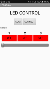
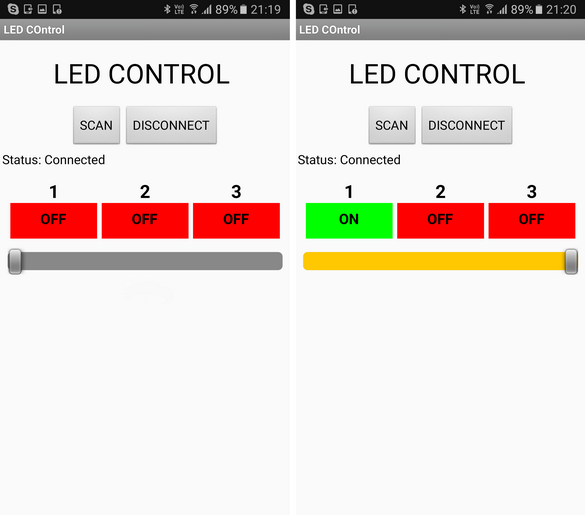
What we have so far
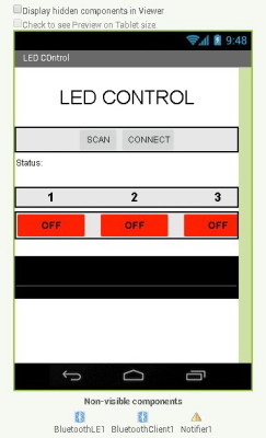
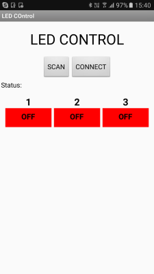
When the buttons are clicked control codes are sent vis BLE to an Arduino.
AI2 sliders
A couple of things to note about sliders in AI2.
- They scale. This means depending on the range (min and max values) and their size they may not go 1,2,3,4 but may jump such as 1,4,7,10. If you have a very large range the sequence may even be 100, 200, 300, etc. This mean you cannot assume you will get number sequences.
- They can also work in fractions, so it is very possible for them to return 1.5, 1.6, 1.7 etc.

The When.Slider.PositionChanged event fires as soon as the thumb position changes, not when it stops. This means if you keep the slider moving it will fire many many times very quickly. This can cause problems when sending data and may flood a connection.
Add a slider to the app
Let’s add a slider under the buttons. Under the buttons we have a label used as padding. To this add another label, then between the two labels add a slider.
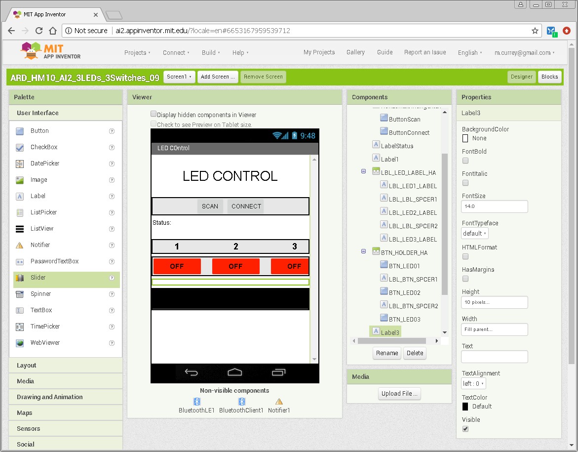
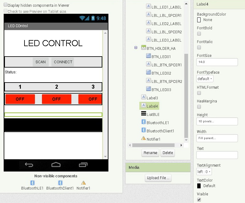
Add another label and give it the same properties as the one above: height = 10px, width = fill parent, no margins, no text.
Drag a slider in to the designer and place between the labels. Set the slider to width = 95%, min = 0, max = 255, ThumbPosition = 0. Change the colours if you wish.
Since we will be controlling the brightness of an LED the maximum value we can use is 255.
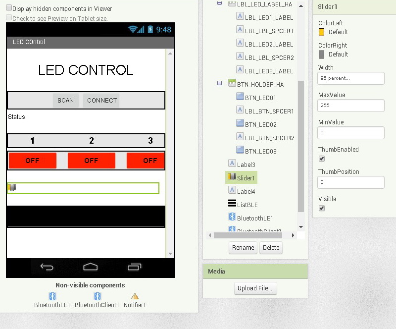
Open the companion app and take a look at we have have so far.
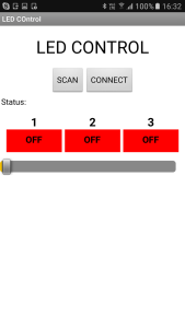
You will notice that the slider is sitting against the left hand side. To centre it, we can use a horizontal arrangement.
Drag over a horizontal arrangement, drop it above the slider, set the width to fill parent and set the horizontal alignment to centre.
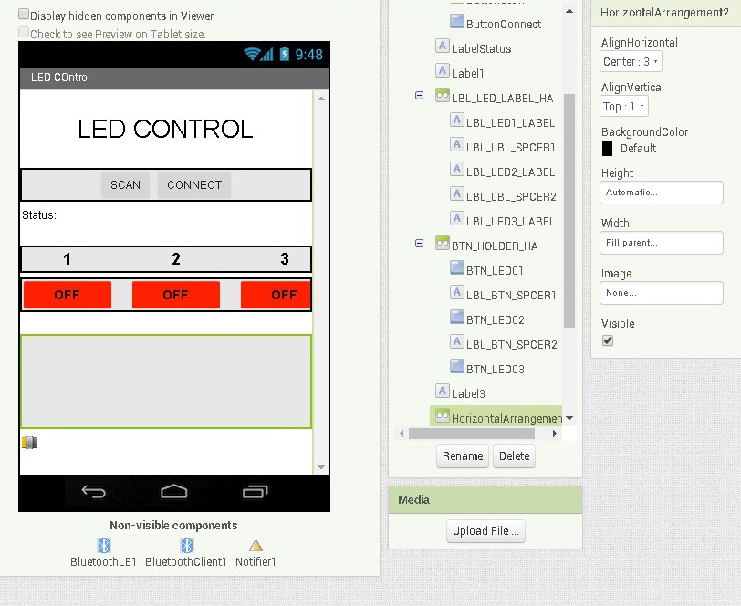
Put the slider inside the horizontal arrangement.
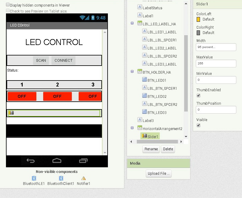
Now the slider is centred.
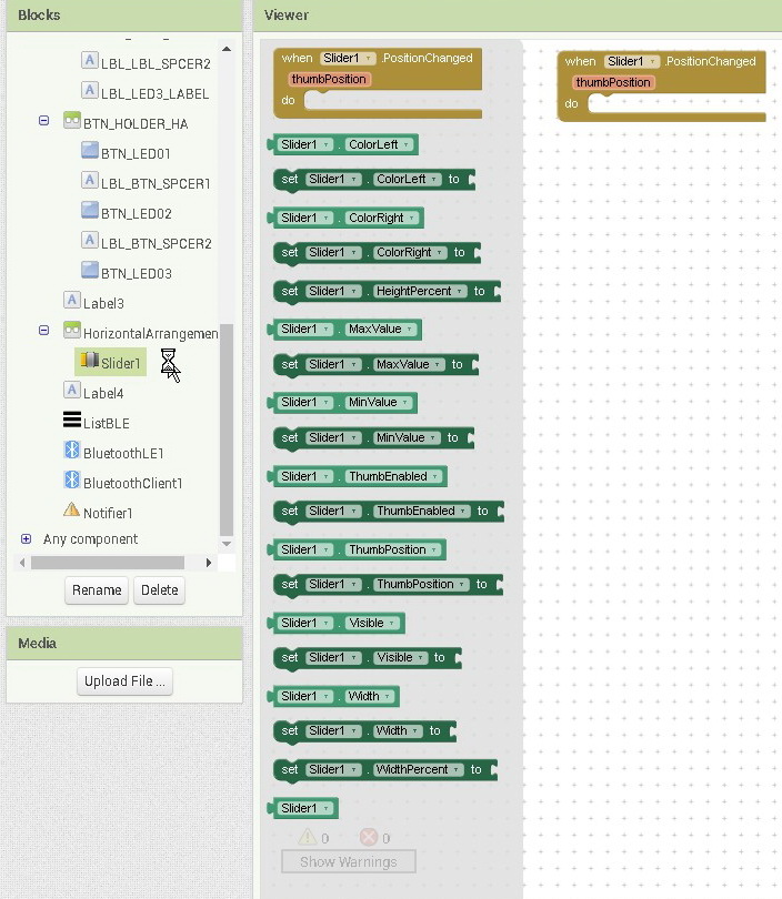
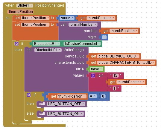
Now when you go to the blocks editor you have the slider in the menu. All we need for now is the When-Slider1.PositionChanged block.
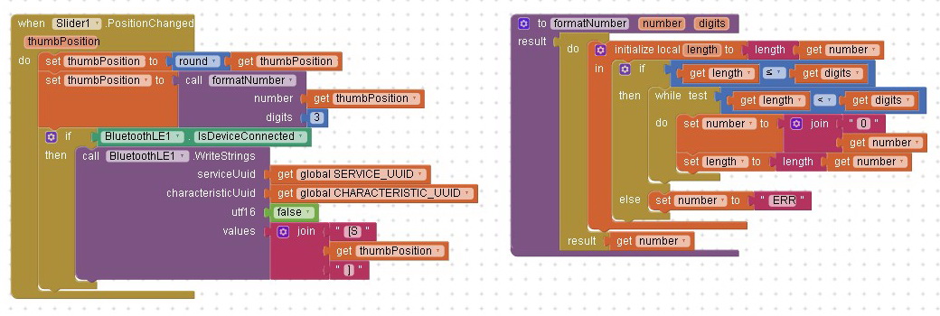
The When-Slider1.PositionChanged block has one property called thumbPosition. This is the current position or value of the slider thumb. I mention at the start that the slider may return a non whole number. You take care of this we can use the math round block. this rounds (up or down) any value to the nearest whole number.
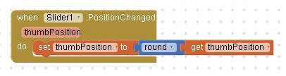
By using Set thumbPosition to round thumbPosition we are asigning the rounded value back to thumbPosition. This measn we do not need to introduce a new variable.
The next step is to create a slider command and send it to the Arduino.
As mentioned at the start, we are using fixed length ascii values; “000” to “255”. Because App Inventor is based on Java we can send the value as a string but the length will vary depending on the value. For example, 5 would be “5”, 50 would be “50” and 200 would be “200”. Therefore we need to make the value 3 characters long. I do this with a small procedure I created called formatNumber. formatNumber allows you to set any desired length.
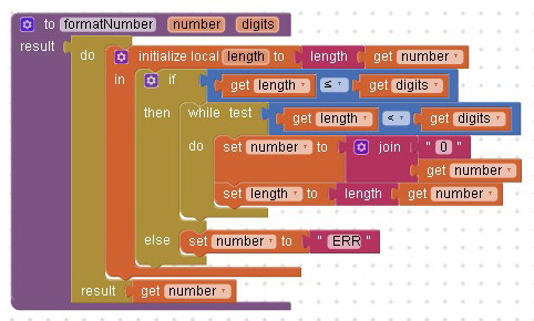
All this does is add leading “0”s to the number.
All that is left to do is to send the number out via the BLE connection
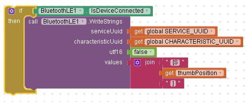
This gives us
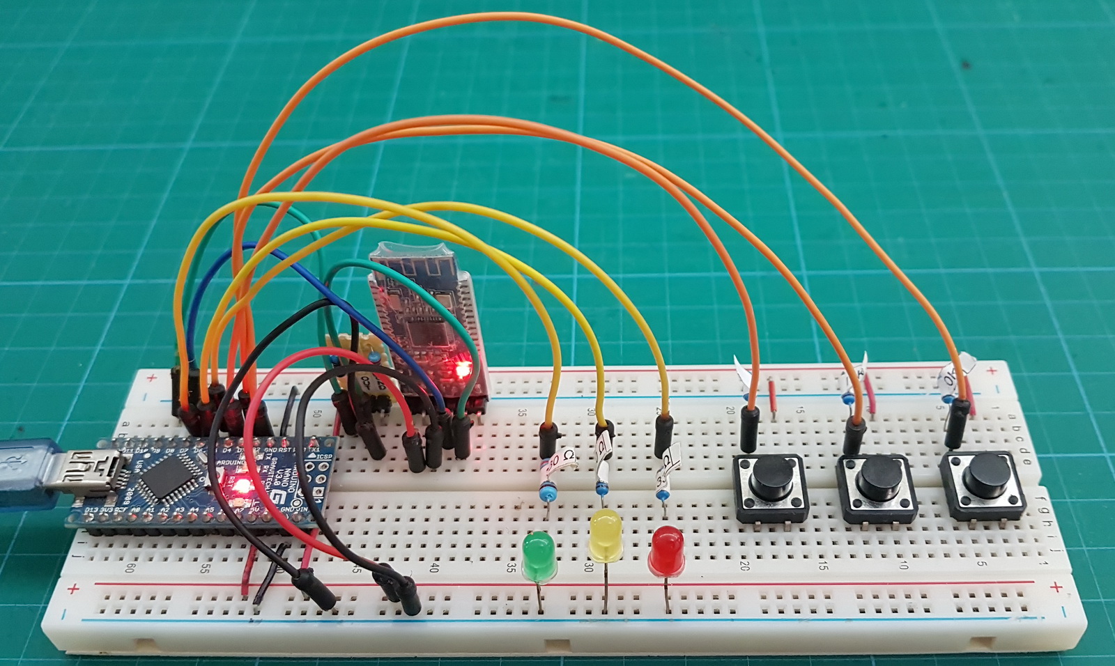
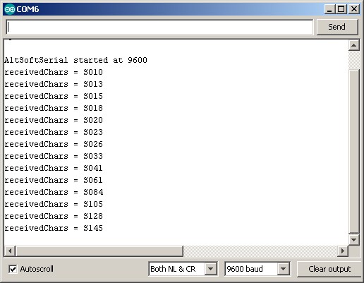
Time to give it a try. We can use the example 5 circuit and sketch from the last guide to test the new app. Since we have not yet updated the sketch we can not yet control the brightness of an LED but we should be able to see the new command in the serial monitor.
Download Arduino Sketch. Example Project Part 5: 3 LEDs and 3 switches
Download ARD_HM10_AI2_slider_001.aia
Upload the sketch, open the companion app, connect to the HM-10 and move the slider. If everything is working you should see the new slider command in the serial monitor.
If not, check the connections.
Arduino sketch
Now that we have the slider commands working it’s time to do something with them. We will use the commands to control the brightness of LED 1. This is the LED connected to pin 5 which is the red LED.
The sketch already has a processCommand() function so we add the code to deal with the new command here.
if (receivedChars[0] == 'S') // do we have a slider command? { // we know the slider command has a fixed length "S123" // and the value at pos 1,2, and 3 is the value. // We need to convert the value from 3 ascii characters to a single value byte hundreds = (receivedChars[1]-48) * 100; byte tens = (receivedChars[2]-48) * 10; byte units = receivedChars[3]-48; byte value = hundreds + tens + units; analogWrite(LED_PIN[0],value); } |
receivedChars[] contains the complete code without the start and end markers. (IE “S123”).
First we check to see if the first character of receivedChars[] is an “S”. If it is we know we have a slider command. If we do have a slider command we know the next 3 characters are the value. These are then are converted from ascii to a numeric value. To get a dimmer effect analogWrite() is used rather than digitalWrite().
Download the updated Arduino Sketch, Example_Project_slider_02, and give it a go.
It works, kind off, but there are problems.
- If you move the slider quickly the commands get corrupted. This is partly due to the serial baud rate used for the HM-10. 9600 is very slow. We can improve this by increasing the baud rate to 115200.
- The slider and on/off controls interfere with each other. Normally you would not have 2 different controls for the same device but we can try to be a bit clever and keep the button as a full on / full off control.
- I also want to change how the on/off button for LED 1 works. I want it to change when the slider is used; be on when the slider position is larger than 0 and off when the slider is 0.
Changing the baud rate is not so straight forward. It is easy to change the BTserial statement to 115200 in the sketch but we also need to change the baud rate on the HM-10 to match and this which requires AT commands. For now I will keep with 9600 and be gentle with the slider. If you are not sure about AT commands on the HM-10 have a look at the HM-10 Bluetooth 4 BLE Modules post.
Updating the sketch
If you only use the slider then the LED fades in and out as expected but the on/off button interferes with it. Also, the on/off button does not change when using the slider. We need to somehow link the two controls and update the on/off button when the slider is used.
There are 2 areas of the sketch that need looking at. Where the switches are checked and where the commands are processed. Lets address the physical switches first. At present all LEDs are controlled with a single digitalWrite() statement.
digitalWrite(LED_PIN[pos],LED_State[pos]); |
Led 2 and LED 3 will still be digital but LED 1 is now analogue so we need to separate LED1 from LED 2 and LED 3 and use different statements.
Here is the new code to look after the button switches.
if ((state1 == state2) && (state1==state3)) { switch_State[pos] = state1; if ( (switch_State[pos] == HIGH) && (oldswitch_State[pos] == LOW) ) { LED_State[pos] = ! LED_State[pos]; // flip the status. // Rather than have a long list of possible commands I create the command as required. // Values in the temp command are replaced depending on which button switch has been pressed. char TMPcmd[8] = "[L,1,0]"; TMPcmd[3] = pos+1+48; // pos+1 should be 1,2, or 3. convert a numeric value to ascii by adding 48. TMPcmd[5] = LED_State[pos]+48; // LED_State should be 0 or 1 if (pos+1==1){ if ( LED_State[pos] ==0 ) { analogWrite(LED_PIN[pos],0); } else { analogWrite(LED_PIN[pos],255); } } else { digitalWrite(LED_PIN[pos],LED_State[pos]); } BTserial.print(TMPcmd); Serial.println(TMPcmd); } oldswitch_State[pos] = switch_State[pos]; } |
Since pos = 0, 1, or 2 (not 1, 2, and 3) and I want the code to be clear I have added 1 to pos before checking it. “if (pos+1==1)”. I can then easily see that we are dealing with LED 1.
If we have LED 1 we need to use analogWrite() to turn it on or off. 0 = fully off and 255 = fully on.
if (pos+1==1){ if ( LED_State[pos] ==0 ) { analogWrite(LED_PIN[pos],0); } else { analogWrite(LED_PIN[pos],255); } |
If we have LED 2 or LED 3 we still use digitalWrite().
else { digitalWrite(LED_PIN[pos],LED_State[pos]); } |
Since I want the buttons in the app to update as before I have left the code the same for all LEDs. This means the LED 1 button in the app updates as before. The slider does not update yet though. Rather than hack the current command I will introduce a new slider command “[S,0]” and “[S,255]” and use this to update the slider position in the app.
To keep things simply I have added the additional code at the bottom of the checkSwitch() function. This makes the code clear but duplicates existing code which is not usually a good idea.
if (pos+1==1){ if ( LED_State[pos] ==0 ) { BTserial.print("[S,0]"); Serial.println("[S,0]"); } else { BTserial.print("[S,255]"); Serial.println("[S,255]"); } } |
Next up. Updating the app to mange the slider in a better way.
Updating the app
We have just added new commands that get sent from the Arduino to the app; “[S,0]” and “[S,255]”. We now need the app to do something with them.
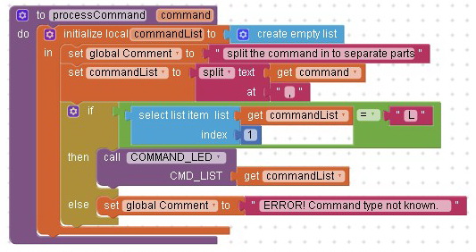
In the app new commands are dealt with in the processCommand function. At present there is only the LED on/off command so the function is fairly basic.
Because scalability was planned from the beginning it is straight forward to add the blocks for new commands. Just add a new if block and a new function.
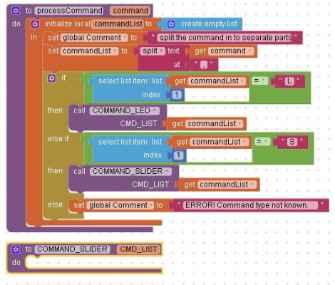
When the physical button switch for LED 1 is pressed, the Arduino sends “[S,0]” for on and “[S,255]” off. All we need do is check for these and move the slider accordingly. No need to worry about the button is the app, this is still being updated from the LED command.
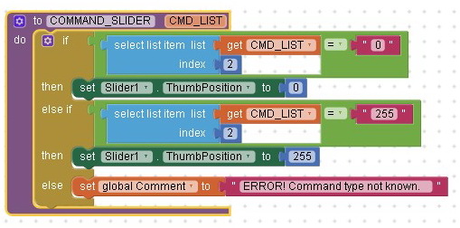
If you remember from the last guide, the received command is split in to a list. Element 1 is S for slider and element 2 is the value. Arrays (lists) in App Inventor 2 start at position 1 not 0 like the Arduino.
If you try this you should now see the slider and the soft button update together.
So far so good. All we need to do now id update the button when the slider is above 0.
If you look at the part of the app that controls the buttons, you can see that there are functions to turn the buttons on and off. We can use these functions in the slider blocks.
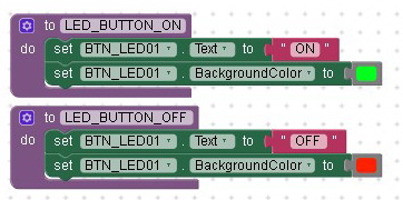
To update the button, when the slider thumb position is greater than 0 call LED_BUTTON_ON and when the value is 0 call LED_BUTTON_OFF.
Now when the slider is used the button updates as it should.
One final thing. Update the slider when the soft button is the app is used. I, as always, keep it simple and add the slider thumb position commands in the button click procedure.
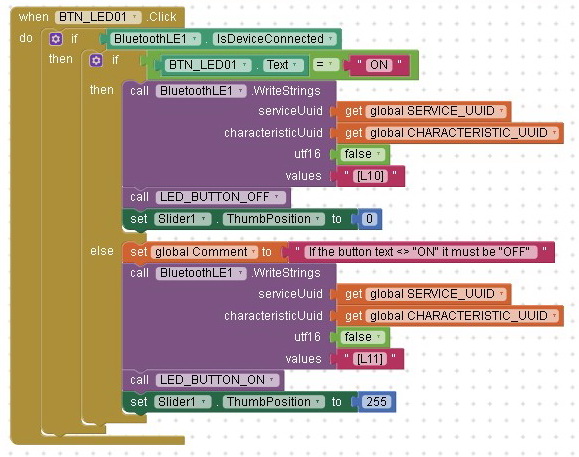
And that’s it. When the soft button for LED 1 is clicked, the slider is set to 0 for off or 255 for on.
Downloads
Final Arduino sketch: Example_Project_slider_04
Final App Inventor 2 aia file
Final Thoughts
This works fine as long as you do not move the slider too quickly. To make the app work better increase the baud rate between the Arduino and the HM-10. I leave this for you to do.
The slider in the app is active all the time, even when there is no BLE connection. A nice touch would be to make the slider active only when there is a connection.
Hi.Thank you for this awesome tutorials. i grateful to you. i have a little hm10 problem. i success ble led control. when i connect dont ask me password. This is unsecure. i change ble name and pin code with at command on Arduino. What can i do? Please help me. Thanks.
By default, the HM-10 is set to not require a password/PIN to pair. You can change this using the AT+TYPE[P1] command. For further details see the data sheet.
Hi~ This is very good~
Hi, thanks so much for your tutorial.
i’have a question about the error “Unable to convert ‘a’ of type gnu.text.Char to type java.lang.String” that occurs when i use the block “join text”. it occurs with all the chars and only if i use the block “join”. what can i do to fix it?
thanks
It appears you are trying to join a non text variable. Check the actual value.
Does anyone have a link to the video version of this?(i know there is one but cant find it).
nice & awesome tutorial :) anyway do you have a sample of how to use speech recognition in appinventor connected to HM10? it would be great for IOT.
Hi, thanks so much for your tutorial.
I needed a lot of resources for the MH-10, and I got a lot of help here.
I will try harder to be someone who can give a lot of help to many people.
If I check the data received from the function “COMMAND_SLIDER” as a number and print it out, I think it will be more complete.
It will be possible only if it is difficult.
It ispossible use Bluetooth HC-05 in the place of BLE HM-10? Thanks.
yes but it is not a direct drop in replacement and you need to change how the connection process works. After a connection is made send data is the same. Have a look at some of the other guides on the site.
Can I use to Connect AT-09 ble for this app. I used but nothing found while scanning.
1 – try scanning again, this time power on the module, use vcc & gnd only, and see if you can find it.
2 – if you can find the module then double check all connections. Have you had it working via serial with replies to AT commands?
3 – some AT-09s have an incorrect crystal which results in them using a slightly out of range frequency. This means they can see each other but are not visible to other BLE devices.
Hi,very nice articles series. I am customizing it to control 4 devices, but the scanning & listBLE part is not working when i import aia file. If i install the apk app from Gplay, the scanning works as expected. I suspect this has to do with ble extension embeded in aia file is not the same version as the one installed in my appinventor. Same thing happens with all your aia files. Somebody knows hot to check the BLE extensión embeded in aia file? Is there a way to replace the aia ble extension without losing all the code?
download the latest BLE extension from http://iot.appinventor.mit.edu/#/bluetoothle/bluetoothleintro
OK, you are right. I whas assuming i had the latest BLE extension, because i downloaded and imported it, but when you import a aia file with the BLE extension, your extension is replaced with it. You need to import again the latest versión. Thank you for pointing me in the right direction.
Hello,
Your app from play store is working on android 10 but the app i generated from AIA doesn’t detect BT devices.
Please can you help me to sort out this problem.
Thank you
You may need the latest BLE extension.
http://iot.appinventor.mit.edu/#/bluetoothle/bluetoothleintro
Help me. I can scan apk on Google Play, but the tutorial’s aia doesn’t scan the device.
I’ve updated BLE up to date, but I can’t do that either. Is there a problem?
Hi Martyn!
I use a Teensy 4.0 with Audioshield.
Do you have any idea how I can use two slider, one for volume and the other for changing the frequence?
Normales, for volume is need a logarithmic slider….
The second slider is the same as the first, except it would require a different name (such as slider2) and the control code/command would need to show the data comes from the 2nd slider. In the above I use [Snnn]. You can keep this the same for the 1st slider and maybe use [Vnnn] for the second. You could use [S1nnn] and [S2nnn] but this adds necessary complexity to the Teensy code.
The sliders can only give a linear scale and you would need to convert this to a logarithmic scale yourself; either in the app, or on the Teensy.
Dear Martyn a very BIG THANKS to you for your excellent Bluetooth + MIT App inventor description.
My project to control Teensy 4.0 + Audio Board via Bluetooth (DM-10) works!
Dear Martyn!
The three sliders work as intended. Now I have a “new” problem with the switches. If one switch has the status (ON), then the others should be locked. If this switch has the status OFF again, then one of another can be pressed.
I have tried to find a way, unfortunately unsuccessfully.
Do you have an idea?
Thanks for the detailed explanation of the BLE communication between Arduino and the MIA application. I have an arduino application for watering a greenhouse. I wanted to add an MIA application for manual valve control and display of temperature, humidity, …. Valve control is the same as LED control. What I don’t know is how best to get get from Arduino in one block temperature (float), soil and air humidity (int), measurement history (char 20). Can I request a code snippet for both MIA and Arduino IDE?