This post follows on from Arduino With HC-05 Bluetooth Module in Slave Mode
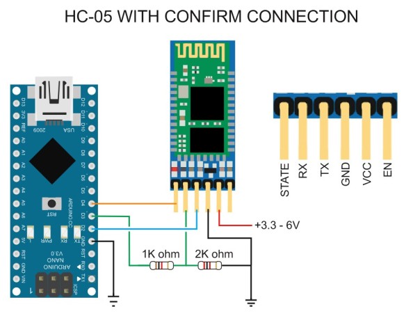
The STATE pin on the HC-05 zs050 board is connected to the LED 2 pin on the small bluetooth module and the LED 2 pin is used to indicate when there is an active connection. This means the Arduino can connect to the STATE pin and determine when we have a connection. The STATE pin is LOW when the HC-05 is not connected and HIGH when the HC-05 is connected.
As a quick visual indicator you can put a LED + suitable resistor on the STATE pin. When the module is connected the LED will light.
You can also use the Arduino to read the value of the STATE pin.
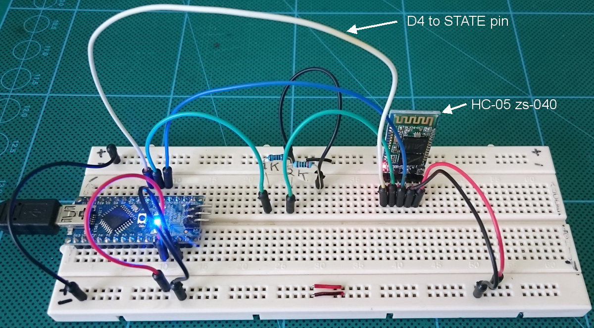
Add a wire from the STATE pin on the HC-05 to the D4 pin on the Arduino
Upload the following sketch. The sketch now waits until pin D4 goes HIGH before starting the software serial and making a connection to the HC-05.
This sketch does not copy what you enter in the serial monitor input field to the serial monitor main window.
// Basic Bluetooth sketch HC-05_03 Using the state pin // Connect the HC-05 module and communicate using the serial monitor // // The HC-05 defaults to communication mode when first powered on. // The default baud rate for communication mode is 9600 // #include <SoftwareSerial.h> SoftwareSerial BTserial(2, 3); // RX | TX // Connect the HC-05 TX to Arduino pin 2 RX. // Connect the HC-05 RX to Arduino pin 3 TX through a voltage divider. // Connect the HC-05 STATE pin to Arduino pin 4. // char c = ' '; // BTconnected will = false when not connected and true when connected boolean BTconnected = false; // connect the STATE pin to Arduino pin D4 const byte BTpin = 4; void setup() { // set the BTpin for input pinMode(BTpin, INPUT); // start serial communication with the serial monitor on the host computer Serial.begin(9600); Serial.println("Arduino is ready"); Serial.println("Connect the HC-05 to an Android device to continue"); // wait until the HC-05 has made a connection while (!BTconnected) { if ( digitalRead(BTpin)==HIGH) { BTconnected = true;}; } Serial.println("HC-05 is now connected"); Serial.println(""); // Start serial communication with the bluetooth module // HC-05 default serial speed for communication mode is 9600 but can be different BTserial.begin(9600); } void loop() { // Keep reading from the HC-05 and send to Arduino Serial Monitor if (BTserial.available()) { c = BTserial.read(); Serial.write(c); } // Keep reading from Arduino Serial Monitor input field and send to HC-05 if (Serial.available()) { c = Serial.read(); BTserial.write(c); } } |
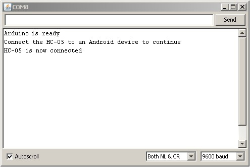
After uploading the sketch HC-05_03 open the serial monitor. You should see:
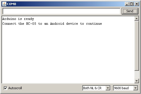
Connect a device to the HC-05
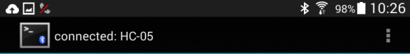
And as soon as the Arduino notices that the HC-05 is connected (pin 4 goes HIGH) it will display the message “HC-05 is now connected”
You can now send messages between the Arduino and the Android device. For more on how to do this see Arduino With HC-05 Bluetooth Module in Slave Mode
You added wire from BT state pin to arduino pin 4.
When you say “As a quick visual indicator you can put a LED + suitable resistor on the STATE pin”, how do you add the LED ? I have tried, but even when BT is connected, the LED is not lightning…
I’m beginner with arduino. I want to use a blue LED but I don’t witch resistor to choose for a blue led, and I don’t how to connect the led (+ to BT module and – to arduino or reverse).
Can you help me ?
Thank’s in advance
First, not all modules are the same. Confirm that the one you have actually sets the STATE pin.
When connected the STATE pin goes HIGH to 3.3v so the pin is providing the power. To the pin connect the LED and a resistor and then to GND. You can calculate the value of the resistor with Ohm’s law. Or use a resistor around 220ohm or 330ohm.
The longer pin on the LED goes to the STATE pin. The longer pin is almost always the + or Anode.
Also look at http://www.instructables.com/id/Identifying-LED-pins/
I am trying to determine how to detect that an HC-05 has gone into AT Command Mode from within my code. If I connect State to a pin and read that pin, I am only determining that the module is paired with another module. Correct? If I read the Enable pin, will that tell me whether the module is in AT Command Mode or not? Haven’t been able to find clear documentation on this.
On most modules, pulling pin34 HIGH will put the module in to command mode. If done after power on, the baud rate is what ever the user has set it to.
So if you control vcc to pin34 you can control going into command mode. You can also add a command check, use AT and check for the OK reply.
Note, some modules have a bug in the firmware. Although bringing pin34 HIGH after power on puts the module in to command mode some commands my not work. To get around this. remove power, bring 34 HIGH, connect power. This will put the module in to command mode at 38400bps.
See the data sheet page 8. https://www.martyncurrey.com/?wpdmdl=2436
Отличная статья. Никак не мог получить состояние модуля. Теперь буду пробовать с ногой STATE и резисторами
Hello Martyn,
I have an HC-05 module. I connected it exactly as your show in your schematic. I entered AT mode and entered “AT+ORGL”. I get out of AT mode and the light on the module flashes very quickly. I then download the code and open the serial monitor window. I connect to the module from my Android tablet, the name appears as “H-C-2010-06-01”. I pair with the module by entering in “1234” as the pin. It now shows that it is connected. The serial monitor only shows “Arduino is ready
Connect the HC-05 to an Android device to continue”.
Any suggestions? Can you recommend a HC-05 from a reputable source that you know sells devices where this will work? I got mine from eBay, but perhaps you know of a reputable seller or shop.
Thanks,
Chase
Hello, my state pin not working. What can i do?
I did exactly your schema and upload your code but firstly I don’t see the HC05 on my phone, I only see it from by PC, and when I want to connect with my pc, it displays “connected” for 1 second and then it deconnects and It does not exit the while loop for waiting the connection. Do you have an idea to solve this problem ?