Update: If you have modules that have a blue LED in the top left hand corner then you have a newer model with a slightly different firmware although they should operate the same.
I recently bought some HC05s and HC-06 Bluetooth modules. These are pretty standard, especially when using with the Arduino and I was surprised at how easy it was to get basic serial communication working. There are several slightly different modules available. The ones I have are marked zs-040. The zs-040 boards differ from some of the other modules in that they have a EN pin rather than a KEY pin.
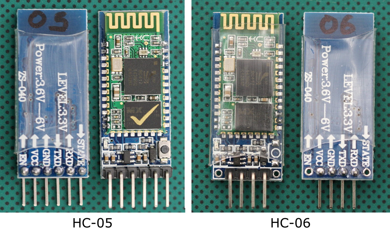
The HC-05 zs-040 and the HC-06 zs-040 use the the same breakout board (even have the same screen print) but have some noticeable differences:
– the HC-06 does not have a button switch
– the HC-06 only 4 header pins
– the HC-06 does not have pins 31-34 connected
They also have a different firmwares. The HC-05 can be a master or slave. The HC-06 is a slave only. This means the HC-05 can initiate a connection to another device and the HC-06 can only accept a connection from another device.
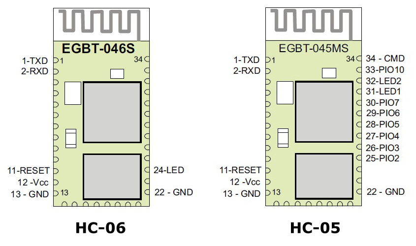
The boards are based on the EGBT-045MS/EGBT-046S Bluetooth modules which are loaded with SPP firmware for UART communication.
Specifications of the EGBT-045MS/EGBT-046S Bluetooth modules
Radio Chip: CSR BC417
Memory: External 8Mbit Flash
Output Power: -4 to +6dbm Class 2
Sensitivity: -80dbm Typical
Bit Rate: EDR, up to 3Mbps
Interface: UART
Antenna: Built-in
Dimension: 27W x 13H mm
Voltage: 3.1 to 4.2VDC
Current: 40mA max
As far as I can tell the EGBT-045MS and EGBT-046S modules have the same hardware and the only difference is the firmware. The different firmware does change the pin outs though.
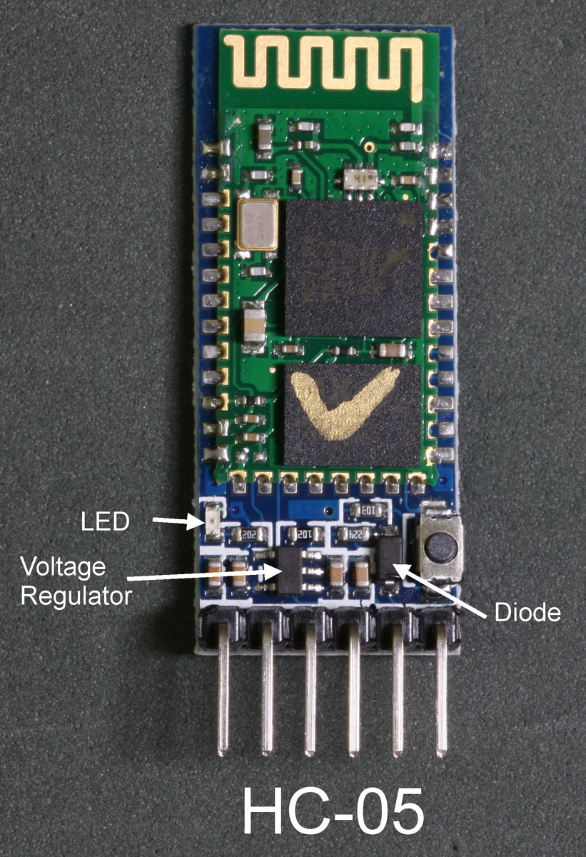
The zs-040 breakout boards include a 3.3v voltage regulator and this allows the boards to accept a VCC of 3.6c to 6v on the main VCC pin/connector. However, the RX and TX pins are still 3.3v.
The Arduino will accept 3.3v as a HIGH signal so the HC-05/06 TX pin (out) can be directly connected to a 5V Arduino. The HC-05/06 RX pin (in) cannot accept 5V though and should not be connected directly to an Arduino. A direct connection will work short term but it damages the small blue tooth module and eventually you will kill the RX pin. The 5V rom the Arduino has to be reduced in some way and a simple way to do this is by using a voltage divider made from 2 resistors. I generally use a 1K ohm resistor and a 2k ohm resistor.
Breakout Board Connections
The below image shows the main traces/connections on the zs-040 breakout board and as you can see, to accomodate the different firmwares certain pins have been connected together.
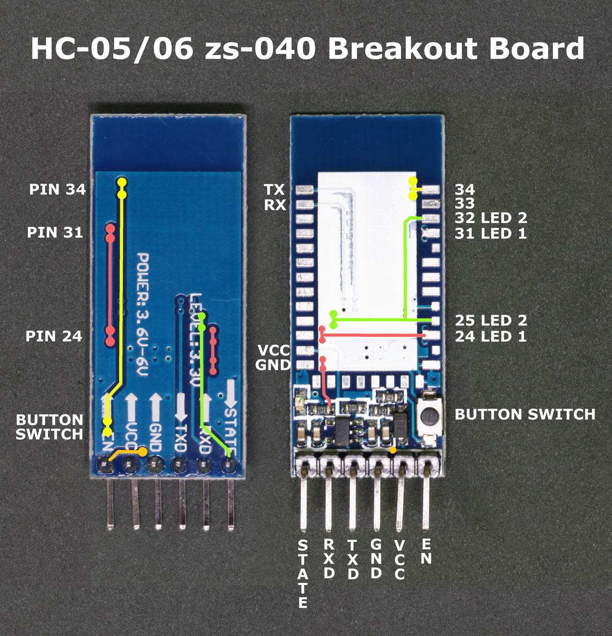
The HC-06 does not have the EN pin or the STATE pin.
LED
The trace between pin 31 and pin 24 on the breakout board links the status LED pin on the EGBT-045MS to the status LED pin on the EGBT-046S. The connection then goes to the actual LED on the breakout board. The connection between pin 31 and pin 24 allows the same breakout board to be used for both the EGBT-045MS and the EGBT-046S
Button Switch
The push button switch connects VCC (3.3v) to pin 34 and is used to put the EGBT-045MS / HC-05 in to AT mode. There are 2 AT modes, I refer to them as “mini mode” and “full mode”. Briefly pressing the button switch puts the modules in to mini mode and not all commands work. Keeping the switch closed puts the modules in to full AT mode where all AT commands work. Releasing the switch returns pin 34 LOW.
For more on AT commands see Arduino with HC-05 (ZS-040) Bluetooth module – AT MODE
Most HC-06 modules do not have the button switch (the space is empty) and bringing pin 34 HIGH on the HC-06 does not do anything.
STATE Pin
From the above photo you can see that the STATE pin is connected to pin 32 and to pin 25 of the small blue tooth modules. Pin 32 is LED2 on the EGBT-045MS/HC-05. Pin 32 is LOW when the module is not connected and HIGH when the module is connected. This gives us an easy way to determine if the HC-05 is actually connected or not. Connect the STATE pin to an Arduino digital pin and if digitalRead() returns HIGH you know the module has an active connection. You can, of course, connect an LED to the STATE pin as a visual indicator of a connection.
I haven’t tried this on a HC-06 yet but since this is not mentioned in the manual I believe it is not active.
EN Pin
Pulling the EN pin on the HC-05 LOW disables the module.
Downloads
EGBT-045MS & EGBT-046S data sheet
Update
I have new HC-06 zs-040 modules that have the hc01.comV2.0 firmware. See here.
EN Pin >——-/\/\/\/\/\——–o——-/\/\/\/\/\——–<VCC Pin
1K | 220K
|
|_____ connet to ON/OFF pin ( LP2985IM5-3.3 Fixed
LDO Voltage Regulator)
ON/OFF Input Operation:
The LP2985-N is shut off by driving the ON/OFF input low, and turned on by pulling it high. If this feature is not to
be used, the ON/OFF input should be tied to VIN to keep the regulator output on at all times.
hello
We followed your tutorial about the hc-05 and hc-06 bluetooth, but when we enter the word “AT”, it doesn’t reply me ” OK”….i don’t know why… :-(
But another thing is we use the arduino board not nano board like yours, is this the reason that we can’t work it out?
If its convenient, could u give us the picture or video and tell me how to connect on the arduino board? Thank u 💖 :-)
Which tutorial?
Thanks for posting this, excellent information.
Cordial saludo, he buscado mucho un dato y lo he encontrado aquí, el pin EN no sabia que hacia y solo pude deducir que tenia algo que ver con el regulador por que lo seguí en la tarjeta, buen apunte, gracias.
Good explanation of the differences. Thank you.
Please can you share the circuit diagram of HC-05 Bluetooth module.
hi friends i have a critical problem.i used hc06 for my circuit with atmega128 and it worked properly,i decided to use sppc-a instead of it becouse of low cost but it dosn’t work(it has EN button and the previous one didn’t)can any body help?
Can a HC06 be replaced by HC05?
yes.
The HC-06 is a slave only device. The HC-05 is slave or master. Just set the HC05 to slave mode.
Thank you Martyn, this is really a useful tutorial. I have searched everywhere and could not get the HC-05 to work nicely in AT_mode with Putty but your tut did the trick. Great work.
Just a word of thanks, Martyn, for this detailed description of this quite awkward module! You helped me get it sorted in the end.
I did a video 4 years ago on the HC 06 and it all “just worked”. Now I wanted the extra STATE pin of the HC-05 for my latest project and it was real trouble getting this working. For others who may read this:
1. The HC-05 runs at 38400 by default (HC-06 at 9600)
2. The HC-05 just refuses to respond sometimes when you type AT. Then it might respond Error(0). Keep persevering, it will eventually respond.
3. You have to be in AT-Mode to do any of this. I had to press the button on my module for a few seconds until the LED started to blink slowly.
4. Changing the name and baud rate were different to the “standard” commands. I had to use AT+UART:9600,0,1 to change the baud rate and AT+NAME:MyName to change the name. Although the HC05 responded OK I could still use 38400 baud rate until I disconnected it, reconnected some time later and waited until it had “reconfigured” itself. Took a little while (couple of minutes).
Only then could I see the new name in my phone’s BT list and connect via the Arduino at 9600 baud rate. Long story short, a very user unfriendly bit of firmware on this module!
5. The STATE header pin was not connected to the EGBT-045MS board. I will have to solder that castellated pin to the carrier module for it to work (tested with multimeter, goes high when connected, low when not).
So a huge thank you for detailing all the pins and so on, this really helped.