In the previous part we used the ESP8266 in Access Point mode where the ESP8266 generated it’s own mini network. Here we get the ESP8266 to connect to an existing wifi network. To do this we use the ESP8266 in Station Mode (STA). Switching to Station Mode is done by the library automatically so we do not need to mess around.
When using the ESP8266 in Station Mode, the connecting device has to be connected to the same network as the ESP8266. In AP mode, since the ESP8266 creates its own network, other local networks don’t matter.
ESP8266 IP Address
In Station Mode the IP address used for the ESP8266 is assigned by the router. This means, depending on your router settings, the ESP8266 could be assigned a different IP address every time you connect to the network. This can be a problem since we need the IP address to connect to the ESP8266 to see the web page.
To know the IP address we will print it to the serial monitor. This is OK while the ESP8266 is connected to a PC but does not work when you want to use it stand alone. This is addressed in part 4.
Known network with unknown IP address
For the first example to work we need to know the network credentials, the SSID and the password and these are hard coded in to the sketch. This is not really a good solution. It means the ESP8266 can only connect to one network and if you want to connect to a different network (or even change the password for the existing network) you need to change the sketch and reupload it. We address that in part 4.
Arduino Sketch: ESP8266_LED_Control_04_Station_Mode
We are using the same sketch as in part 2 but changing the part that deals with the connection and starting the web server. I will show the sketch first and then explain the changes.
/* * Sketch: ESP8266_LED_Control_04_Station_Mode * Control an LED from a web browser * Intended to be run on an ESP8266 * * Wait for the ESP8266 to connect to the local wifi * then use a web broswer to go it's ip address * */ #include <ESP8266WiFi.h> // change these values to match your network char ssid[] = "MyNetwork_SSID"; // your network SSID (name) char pass[] = "Newtwork_Password"; // your network password WiFiServer server(80); String header = "HTTP/1.1 200 OK\r\nContent-Type: text/html\r\n\r\n"; String html_1 = "<!DOCTYPE html><html><head><meta name='viewport' content='width=device-width, initial-scale=1.0'/><meta charset='utf-8'><style>body {font-size:140%;} #main {display: table; margin: auto; padding: 0 10px 0 10px; } h2,{text-align:center; } .button { padding:10px 10px 10px 10px; width:100%; background-color: #4CAF50; font-size: 120%;}</style><title>LED Control</title></head><body><div id='main'><h2>LED Control</h2>"; String html_2 = ""; String html_4 = "</div></body></html>"; String request = ""; int LED_Pin = D1; void setup() { pinMode(LED_Pin, OUTPUT); Serial.begin(9600); delay(500); Serial.println(F("Serial started at 9600")); Serial.println(); // We start by connecting to a WiFi network Serial.print(F("Connecting to ")); Serial.println(ssid); WiFi.begin(ssid, pass); while (WiFi.status() != WL_CONNECTED) { Serial.print("."); delay(500); } Serial.println(""); Serial.println(F("[CONNECTED]")); Serial.print("[IP "); Serial.print(WiFi.localIP()); Serial.println("]"); // start a server server.begin(); Serial.println("Server started"); } // void setup() void loop() { // Check if a client has connected WiFiClient client = server.available(); if (!client) { return; } // Read the first line of the request request = client.readStringUntil('\r'); if ( request.indexOf("LEDON") > 0 ) { digitalWrite(LED_Pin, HIGH); } else if ( request.indexOf("LEDOFF") > 0 ) { digitalWrite(LED_Pin, LOW); } // Get the LED pin status and create the LED status message if (digitalRead(LED_Pin) == HIGH) { // the LED is on so the button needs to say turn it off html_2 = "<form id='F1' action='LEDOFF'><input class='button' type='submit' value='Turn off the LED' ></form><br>"; } else { // the LED is off so the button needs to say turn it on html_2 = "<form id='F1' action='LEDON'><input class='button' type='submit' value='Turn on the LED' ></form><br>"; } client.flush(); client.print( header ); client.print( html_1 ); client.print( html_2 ); client.print( html_4); delay(5); // The client will actually be disconnected when the function returns and 'client' object is detroyed } // void loop() |
Changes to the sketch
Because we are connecting to an existing network the ESP8266 needs to know the SSID (name) and the password for the network. This is handled with a couple of char arrays. Remember to enter you own details before uploading the sketch.
char ssid[] = "MyNetwork_SSID"; // your network SSID (name) char pass[] = "Newtwork_Password"; // your network password |
Since we are printing the IP address to the serial monitor we need to start a serial connection.
Serial.begin(9600); Serial.println(F("Serial started at 9600")); |
The wifi.begin command is used to try and make a connection and the command uses the char arrays “ssid” and “pass”. You do not need to use variables and can use literal values in the command if you wish.
A connection is not established straight away and so we may need to wait a short while. When a connection is successful the variable wifi.status will be set to equal WL_CONNECTED. At this point we know we are connected.
The sketch keeps checking for a successful connection and does not move on until it has one. This is not good practise, ideally there should be a time out and an error message.
Serial.print(F("Connecting to ")); Serial.println(ssid); WiFi.begin(ssid, pass); while (WiFi.status() != WL_CONNECTED) { Serial.print("."); delay(500); } Serial.println(""); Serial.println(F("[CONNECTED]")); |
After we have a connection we can print the IP address
Serial.print(WiFi.localIP()); |
All that is left to do now is to start the server. When using Station Mode, the wifi library does not automatically start a server we need to do it manually. When using AP mode it is done for us.
server.begin(); Serial.println("Server started"); |
Give it a go
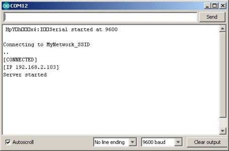
Load the sketch in to the Arduino IDE, change the network SSID and password and upload to the ESP8266 and open the serial monitor. If everything is good you should get something like this:
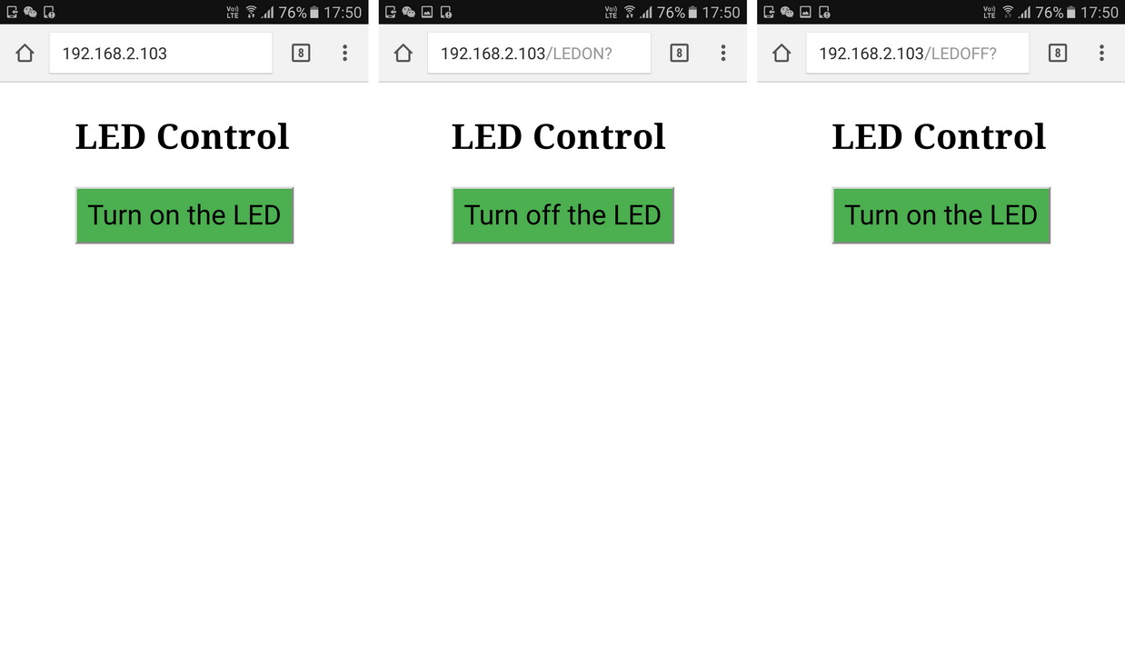
Now, using your device of choice, open a web browser and go to the IP address shown in the serial monitor. Mine is 192.168.2.103, yours will be different.
You should see the same page as before and when you click the button the LED should turn on and off.
Because the ESP8266 is now on the local network you can use any other device that is connected to the same network to view the ESP8266’s web page. You do not need to use mobile devices you can use a PC.
While this works it is not very convenient. To know the ESP8266s IP address we need to use the serial monitor. This is OK for demos and examples but not suitable for real world applications where we want to use the ESP8266 stand-alone. In the next part we look at ways to address this.
Download sketch: ESP8266_LED_Control_04_Station_Mode.
I liked your work, it is very well done. in the smallestdetail. very good
Votre site est vraiment excellent il contient des détails appréciables. Merci pour ce travail et bonne continuation.
Thanks, for this project, this is the first time that I could get a esp8266 to
work. Keep up the good work , Michel Adriaens.