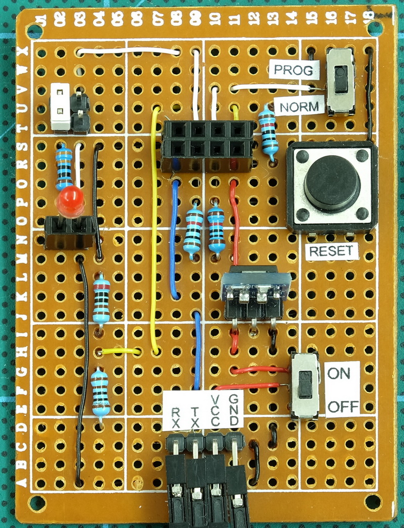
Here is my 5V ESP8266-01 programming breakout board.
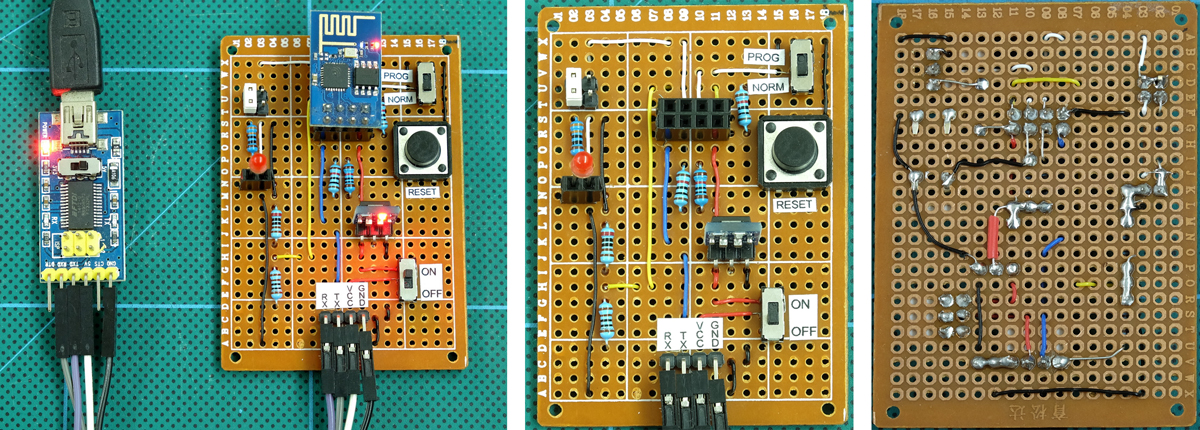
I am now programming the ESP8266’s via the Arduino IDE and I found using bread boards and wires was annoying, especially because I have a habit of VCC and GND mix up. I have a small pile of dead ESP8266-01s, dead due to shorting them while moving wires around. They are next to the pile of Arduino Nanos I have killed for the same reason.
Since starting to use the ESP8266’s again I have made a couple of breadboard friendly breakout boards. Version 1 worked but moving wires was inconvenient (the ESP8266 was in the way). Version 2 was better but I still had to mess with power, resistors and lots of wires. This lead me to version 3. A fully self contained programming breakout board.
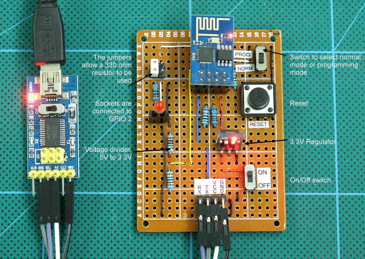
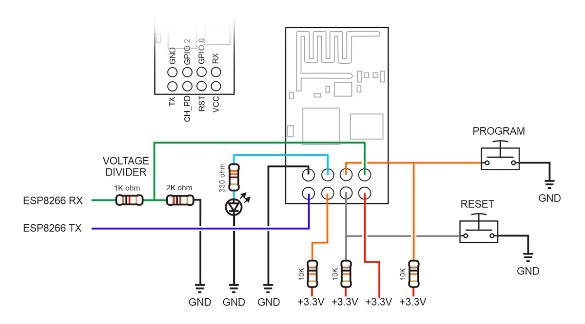
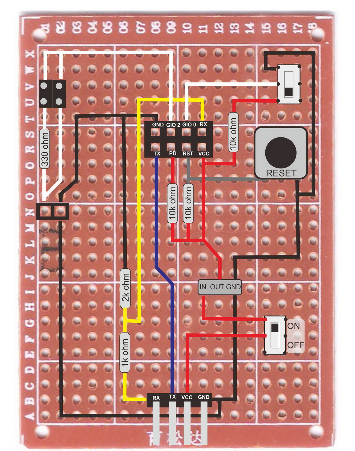
Here with the ESP8266-01 and a LED attached. The LED is connected to GPIO 2. The jumpers above the red LED allow a 330 ohm resistor to be used. Move the jumper to the right hand side and the sockets are connected to GPIO 2 without the resistor.
For normal startup CH_PH should be brought HIGH. I do this with a 10K pullup resisitor.
To enter programming mode, GPIO 0 has to be brought LOW on start up. The switch on GPIO 0 allows for this.
To reset the module, bring RESET LOW. Another switch allows for this.
To enter programming mode, press and hold the PROGRAM button switch, press the RESET button switch, release the PROGRAM switch.
Version 4, if I ever build one, with have female connectors not pins and the positions will match the usb-to-serial adapter so that I can attached the adapter straight to the programming board.
I would also put the LED holder vertically and maybe put the LED resistor above the jumpers (there is no technical reason for this but it might look better).
Circuit
The switch used to enter programming mode could be swapped out for a button switch.
3.3 voltage regulator
The 5V to 3.3v regulator is a small board I bought from taobao. Small and self contained. Good for creating a 3.3v supply but not fast enough to use on the RX line.
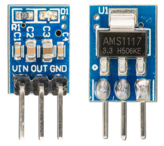
The small power regulator can be swapped out and there is space on the board to add something like a LD1117V33 or a LM3940 and a couple of capacitors.
To bring the RX line down to 3.3v I am using a voltage divider made from a 1k ohm resistor and a 2k ohm resistor.
so simple
Awesome build, and an even better write up, thank you. I learnt a lot, not just how to build, but various design thinking I can use in other projects.