A very short post I made sometime ago has been more popular that it should have been. It wasn’t particularly detailed and it was in desperate need of an update. So here is the update, this time giving more details and adding mosfets.
Arduinos are limited in the current and voltage they can supply. A typical 5V Arduino can provide 5V and 3.3v at a maximum 40mA from a single pin. 40mA is the maximum and ideally the current draw should be kept to around 20mA. 20mA is fine for a LED but not so good for motors, solenoid valves or long strings of RGB LEDs. For these we need a separate power supply and a way of controlling it.
One of the problems many beginners have is knowing what can be connected to and Arduino and what should not be. This post does not really help with this except to show how to use a high voltage/high current device with the Arduino. The high voltage/current is not connected directly to the Arduino but it can controlled by the Arduino by using devices that act as digital switches.
Knowing what to connect and what not to comes from experience and a little understanding of volts and current. I do not cover this here beyond saying voltages should match and currents are more difficult to determine. I have killed/partially killed more things because of current than I have because of volts simply because most things clearly say what voltage they are, A 24v power supply says 24v on it and I know I shouldn’t connect it to an Arduino. A very small 6v motor that looked like it hardly required any power melted an Arduino within seconds. Finding a devices current requirement may mean reading data sheets and extensive online searches. Unfortunately Arduinos do not give a warning when a device wants more current than they can supply, they simply try to provide it. This leads to over heating and mini explosions (or at least a dead Arduino and the smell of burnt plastic).
In this post I am using DC voltage solenoid valves only. Valves that use AC have very different requirements and the below does not apply. Most DC solenoid valves tend to use a voltage any where from 6v up and 12V and 24V are very common. The one I am using below is 24v. The Arduino cannot handle these voltages and so cannot (or should not) be connected directly to the valve. Instead, we use another device as a middleman, one that can accept the 5v signal from the Arduino as a control signal and also handle the higher voltage and current required by the valve. There are various different devices that can fulfill this role. I am using transistors. The Arduino controls the transistor and the transistor controls the valve. A simple way of thinking about this is we are using the transistor as a switch. The Arduino is controlling the switch and the switch is controlling the valve.
There are many transistors you can use and you pick one depending on the voltage and current you need to control. To know the voltage and current required means knowing about the device you want use. Here I am using the good old TIP120 and the IRLZ44N mosfet. Why these 2 devices? Because they are what I have. They were purchased some time ago purely because they are suitable for use with 5v Arduinos.
TIP120
The TIP120 is, by electronic standards, an old device and there is a lot of talk on the internet about how it is passed its prime and never the best option. Being old though, it well tested, proven to be very reliable, and cheap. They can be very cheap. A while ago I bought 1000 of them in a clearance sale for around 4 USD. I still have most of them in a box somewhere.
The TIP120 is a NPN Darlington pair transistor, which means it is two transistors, one piggy backed on top of the other, the first one driving the second one. The current amplified by the first transistor is amplified further by the second transistor. This allows a very small voltage to switch a very large voltage. The TIP120 can handle 60v up to 5 amps. These are the maximum ratings so the TIP120 should not really be used at this level. My valve is 24V and rated for 0.275 amps so well within the limits of the TIP120.
One downside to the TIP120 is the voltage drop across CE. This can be anything from 2v to 4v depending on the current and means the 24v supply is reduced to around 22v by the time it gets to the valve.
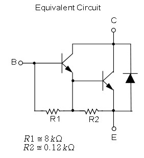
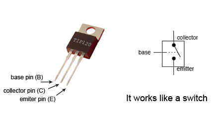
In the example below the TIP120 can be thought of as a switch and applying a current to the Base pin allows current to flow between the Collector pin and the Emitter pin.
IRLZ44N mosfet
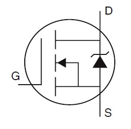
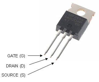
The IRL44N mosfet is a logic level N-channel mosfet which means it can be controlled from a logic level voltage of 5V. There are also 3.3v logic level mosfets so when selecting a mosfet double check the data sheet. There are many similar mosfets that can be used in exactly the same way.
N-channel mosfets are voltage driven and require very little current. They also have very little voltage drop across drain-source. The actual voltage drop is dependent on the mosfets RDS(on) property. So the lower the RDS(on) the better. The IRLZ44N has a RDS(on) of 17.5mΩ, not bad, and can handle 55v at 49 amps (remember these are maximum ratings, don’t actually use it at this level).
I am using the mosfet as a switch exactly like the TIP120. But why bother with a mosfet? There a few advantages. Mosfets are voltage driven so we don’t need to worry as much about current, they are more efficient than TIP120s so we do not need to care as much about total power and heat, and they switch quicker. You can also get away without a resistor so there is one less component. However, not using a resistor is not always recommended. When the mosfet first opens it acts like a capacitor and can briefly draw a fairly large current. And, if you use a mosfet for fast PWM then you may get issues with gate ringing and adding a small resistor (up to 100 ohms) will reduce it (in my own projects I typical use 200 ohms).
Main Differences
Voltage drop
Darlington pair transistors have a considerable voltage drop across emitter and collector.
Mosfets don’t have a specified voltage drop but instead have a drain-source ON resistance (RDS-on) which is normally very small and results is a low voltage drop.
Base/Gate drive
Transistors are current driven and require a current limiting resistor on the Base pin.
Mosfets are voltage driven and require hardly any current on the Gate pin but does need enough voltage. This means a resistor on the Gate is not always required.
Please be aware there is far more to it than this. If you are using either a transistor or a mosfet for other things (like PWM) then there are other things to consider.
Solenoid Valve
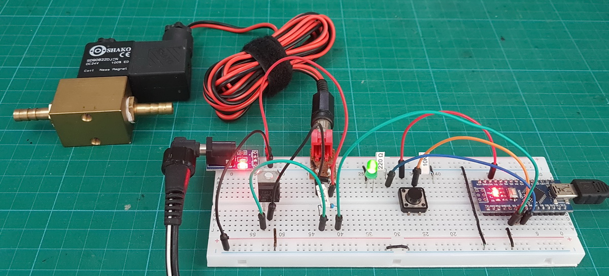
For the following examples I am using a Shako PU220AR Solenoid valve with 24v coils. These draw around 0.275 Amps. The valve is a normally closed and uses an electromagnetic coil to open. Apply a current the coil charges creates a magnet that moves a plunger which opens the valve. Stop the current the plunger moves back and the valve closes (other valves can work in different ways).
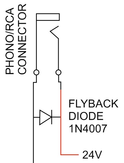
Flyback Diode
When you remove power from an electromagnet, the magnetic field collapses creating current (the coil is an inductive load). This current can be very high and can be powerful enough to kill an Arduino. To stop this happening we add a flyback diode (AKA a snubber diode, freewheeling diode, and many other names). The diode allows current to move in one direction only and safely dissipates the current created by the collapsing magnetic field. This can slow the decay slightly but for use with solenoids this is not noticeable, the valve is much slower.
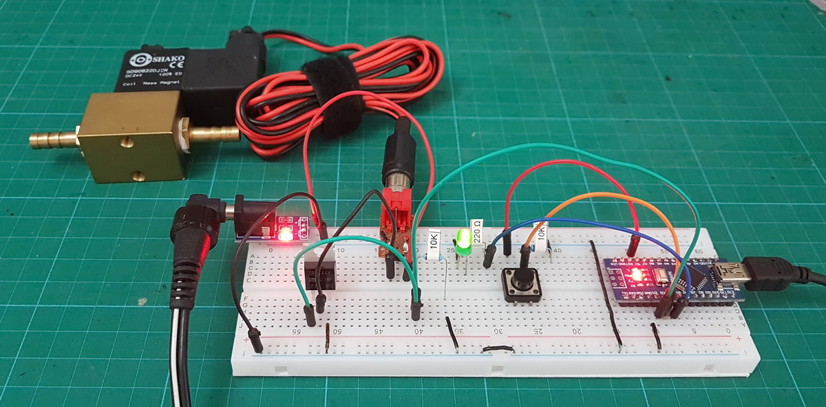
Circuit using TIP120
Here we have a very basic circuit. Note that all GNDs are connected. DO NOT CONNECT THE 24V WITH THE 5V!
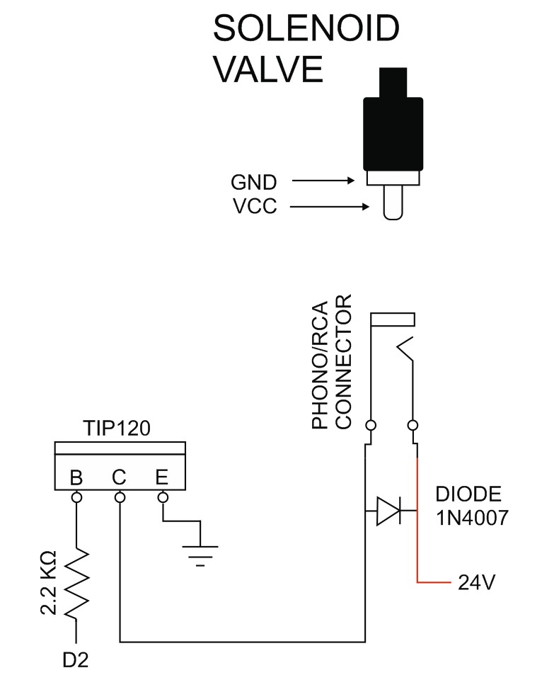
When we set Arduino pin D2 high, the transistor activates and allows current to flow to the valve.
Sketch
// Arduino_Solenoid_Valve_01 byte LED = 13; byte Valve = 2; void setup() { pinMode(LED, OUTPUT); pinMode(Valve, OUTPUT); } void loop() { digitalWrite(LED, HIGH); digitalWrite(Valve, HIGH); delay(1000); digitalWrite(LED, LOW); digitalWrite(Valve, LOW); delay(1000); } |
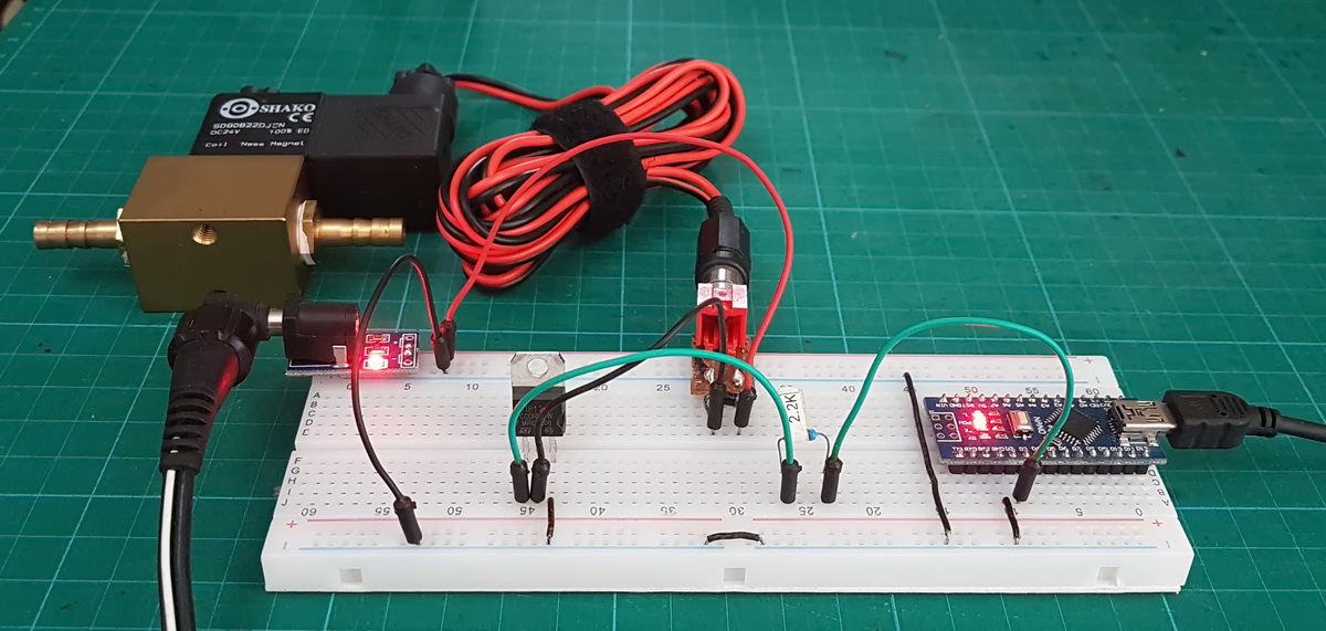
The sketch switches the valve on and off every second. It’s the blink example with an extra couple of lines of code. Hard to tell from the photo above but when running the valve clicks as it opens and closes in sync with the Arduinos on board LED.
Bonus
Here is a bonus circuit and sketch that uses a button switch to turn the valve on and off. First press opens the valve, second press closes it. If you want to know more about how the sketch works see Switching Things On And Off With An Arduino
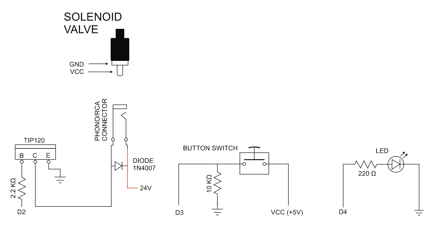
Note that all GNDs are connected. DO NOT CONNECT THE 24V WITH THE 5V!
// Arduino_Solenoid_Valve_02 byte Valve = 2; byte Switch = 3; byte LED = 4; // variable to hold the valve state boolean valveState = LOW; // variable to hold the switch state boolean oldSwitchState = LOW; // used for simple debouce boolean newSwitchState1 = LOW; boolean newSwitchState2 = LOW; boolean newSwitchState3 = LOW; void setup() { pinMode(LED, OUTPUT); pinMode(Valve, OUTPUT); pinMode(Switch, INPUT); } void loop() { newSwitchState1 = digitalRead(Switch); delay(1); newSwitchState2 = digitalRead(Switch); delay(1); newSwitchState3 = digitalRead(Switch); // if all 3 values are the same we can continue if ( (newSwitchState1==newSwitchState2) && (newSwitchState1==newSwitchState3) ) { if ( newSwitchState1 != oldSwitchState ) { oldSwitchState = newSwitchState1; // has the button switch been closed? if ( newSwitchState1 == HIGH ) { if (valveState==LOW) { valveState=HIGH; digitalWrite(LED, HIGH); digitalWrite(Valve, HIGH); } else { valveState=LOW; digitalWrite(LED, LOW); digitalWrite(Valve, LOW); } } } } } |
How to calculate the resistor value
The TIP120 is a current driven device and will, given the chance, try to use as much current as possible, sucking the life out of the Arduino. This is not good, so we add a current limiting resistor to stop it happening. So what resistor to use? I generally use 2K2. Why? because I am lazy and it is what the internet says.
I don’t go in to the full details on how to select a resistor, there are far better explanations than I can offer online, google “How to calculate TIP120 resistor value”, but the basics are as follows.
A few of things we need to know before starting to calculate:
– what current an Arduino is able to deliver. Safely this is 20mA. Max is 40mA.
– what current the valve uses when active. This is 275mA or 0.275A.
– the TIP120 data sheet.
– from the data sheet – DC gain
– from the data sheet – Vbe
– From the data sheet – Vce
The load (the current the solenoid needs) is 275mA or 0.275A. This is the collector current (Ic).
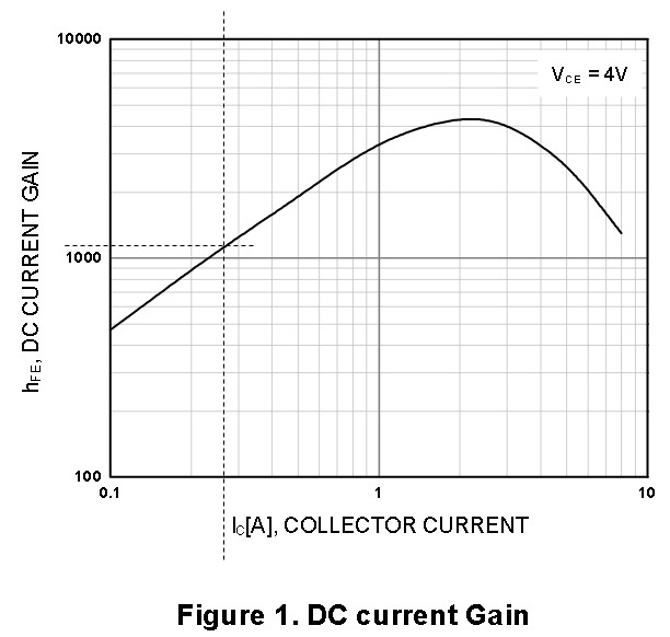
The DC gain at 275mA (according to the data sheet) is around 1200. Diagram 1.
Vbe is around 1.4v. Diagram 1.
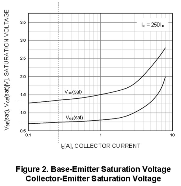
Vce at 275mA is around 0.75v. Diagram 2.
In order to switch 275mA we calculate the Base current using Ib = Ic / DC gain.
Ib = Ic / DC gain or 0.275A/1200 = 0.000229uA. The general internet rule of thumb is to use Ib x 5 which gives us 1.15mA.
Now we can use ohm’s law to work out the resistor value.
Resistor value (Rb) = (5v-1.4) / 1.15mA. Rb = 3.6/1.15. Rb = 3.13 or 3K13 Ohms.
And for good measure we can work out the power consumption with P = Ic * Vce
Power = 0.275A * 0.75v = 0.2 watts. This tells us if we need a heat sink or not.
A 3K13 or 3K3 ohm resistor is the best case scenario and may cause the TIP120 to be borderline saturated (When using a TIP120 as a switch we need to make sure it is fully saturated or it doesn’t turn all the way on). To ensure the TIP120 is fully saturated we lower the resistor value, I normally go with 2K2 and for the valve I am using could probably go to 1K. I’ll stay with 2K2 because that is what I generally use and also have one on hand.
Edit 30.09.2019
The above is how I work out the resistor value when I need to, I must admit I generally just guess though, however, leovd contacted me to say I am using the wrong method.
As stated many times on the Arduino forum, don’t calculate/use Hfe for a saturated switch. Hfe does not apply when a transistor is reverse biased (collector voltage lower than the base). The datasheet clearly states a 1:250 B/E current for saturation of this darlington (inside one of the graphs). Just stick to that. Regards, Leo..
Circuit using IRLZ44N Mosfet
The circuit for the mosfet is very similar to that of the TIP120 and although the pins on the mosfet have different labels the connections are basically the same. You should notice that we no longer have the current limiting resistor but we do now have a 10K resistor that pulls the pin to ground. This stops it floating and causing issues.
When used as a basic switch, there is no need to add a resistor to the Gate of the mosfet. If you use a mosfet with a fast switching signal then there may be issues with gate ringing and a small resistor can help.
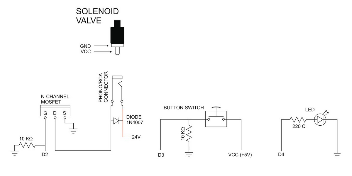
Note: The above circuit does not include a resistor on the mosfet gate pin between the pin and the Arduino. To err on the side of caution add a small resistor, 100-200 ohms.
Sketch
Because we are using the same pins as above the sketch has not changed.
// Arduino_Solenoid_Valve_02 byte Valve = 2; byte Switch = 3; byte LED = 4; // variable to hold the valve state boolean valveState = LOW; // variable to hold the switch state boolean oldSwitchState = LOW; // used for simple debouce boolean newSwitchState1 = LOW; boolean newSwitchState2 = LOW; boolean newSwitchState3 = LOW; void setup() { pinMode(LED, OUTPUT); pinMode(Valve, OUTPUT); pinMode(Switch, INPUT); } void loop() { newSwitchState1 = digitalRead(Switch); delay(1); newSwitchState2 = digitalRead(Switch); delay(1); newSwitchState3 = digitalRead(Switch); // if all 3 values are the same we can continue if ( (newSwitchState1==newSwitchState2) && (newSwitchState1==newSwitchState3) ) { if ( newSwitchState1 != oldSwitchState ) { oldSwitchState = newSwitchState1; // has the button switch been closed? if ( newSwitchState1 == HIGH ) { if (valveState==LOW) { valveState=HIGH; digitalWrite(LED, HIGH); digitalWrite(Valve, HIGH); } else { valveState=LOW; digitalWrite(LED, LOW); digitalWrite(Valve, LOW); } } } } } |
Final Notes
In this particular example the solenoid valve does not require that much current and the TIP120 is probably over kill and a regular transistor could be used. A regular transistor is used in exactly the same way as the TIP120 but it will have lower capabilities (smaller voltage, smaller current).
Is a mostfet or a TIP120 better? In most cases a mosfet is better. They use a newer technology, are more efficient and do not have the large voltage drop the TIP120 has. Having said that, if you have a TIP120 there is no reason not to use it.
TIP120, TIP121, and TIP122 are mostly interchangeable. The difference is the TIP121 and TIP122 can handle larger voltages.
This is incredibly perfect timing and great reference material for my project, thank you so much!!
Hello Sir,
In this concept Arduino Controller is to be used……but if we want to apart from this arduino controller then …. can be used???
Please Advise
Hi Martyn,
Thanks for the great post! I am working on a project involving Water solenoid valve but unable to make it work. It is 24v DC valve. Does it require 24v power supply or 12v power supply would work?
A 24v valve requires 24V, however, depending on the valve there is probably a working voltage range. For example, I have some 12V solenoids that have a working voltage range of 10v-18v. Check the data sheet for the solenoid you have.
It is also worth mentioning that the coil on most valves (the black plastic part) can be replaced. The Shako in the photo above has a 24v coil but I also have 12v coils I can swap with should I need to.
If speed is important; higher voltage solenoids open (very slightly) faster than low voltage ones.
Thank you for the post. In my project, I have to close the solenoid valve at a different rate of time (for each reading). Do you think by changing the delay time I will be able to do that?
delay() will work, simply use the Blink example as a starting point but a better solution would be to use millis(). millis() will give you far more flexibility. I don’t have an example but if you search online you will find many guides.
irfz44n is NOT a logic level mosfet!
Thanks for the heads up. I can’t believe I used the wrong part number.
Have corrected the post.
Hi, I was wondering what the 24VDC power source is that you’ve attached to the breadboard, and how you’ve attached it? And also what you’ve used to attached the solenoid to the board. It looks very neat, and I would like to emulate it!
HI,
In this case the power supply is an adjustable wall-wart I bought from a local hardware store (3.3, 6,7.5,9,12,24V). I also use fixed voltage 12 and 24v PSUs.
The barrel jack mini pcb with breadboard friendly pins I bought of the internet. I soldered pins to the connectors on the RCA/Phone socket to get it to fir the breadboard.
See https://www.dropcontroller.com/dropcontroller-diy-breadboard/#RCA_sockets_and_power_barrel_jack_socket
The project in the link is the reason I started playing with valves in the first place.
Thank you so much! That’s incredibly helpful. My project relies on everything being very neatly organised and this will be perfect! Thanks again for taking the time to reply :)
I am using this to water my greenhouse. I’ve noticed that the arduino board is showing some corrosion due to humidity. Can I spray the board with paint to protect it?
yes with care. Be careful that the paint is not conductive and does not cause heat issues. You could also try a water tight container.
DeoxIT might do the trick and be less permanent than paint. Red version to clean and gold one to protect after it.
Hi,
thanks for this incredible post.
Is there a specific reason to not use a ULN2003 or similar?
I think the circuit will be simpler.
What do you think?
Thanks in advance
I don’t have any ULN2003s. I do have lots of TIP120s and a few IRL44N mosfets though :-)
Thanks for the fast reply.
I would say that’s a very good reason to use TIP120 😁
I found my ULN2003 on a cheap chinese board for 28byj stepper motor.
Do you think it can work as well as yours?
I also have them on cheap
12v5V stepper motor drivers! Probably the same board.ULN2003 is a set of Darlingtons inside a single package and for the 24v valve I used above they would be OK. The specs are slightly different to the TIP120 though so double check the data sheet and make sure they are OK for your own project.
Thanks, I’m having some problem, if i don’t resolve them I’ll go back to tip120 😁.
happy holidays
Hi! Thanks for the great post. I am looking to incorporate the switching of the solenoid with a button into another sketch I have, I therefore want to avoid delay() as I don’t want to stop other functions in the sketch from performing. Could you give me an example using for example millis() here? I’m a rookie!
newSwitchState1 = digitalRead(Switch); delay(1);
newSwitchState2 = digitalRead(Switch); delay(1);
newSwitchState3 = digitalRead(Switch);
Have a look at the switching things on and off post – https://www.martyncurrey.com/switching-things-on-and-off-with-an-arduino/
Hi,
I followed the MOSFET circuit, used the code as well but it is not working. The 24v solenoid valve is not turning ON/OFF when I pressed the button switch. What do you think is the problem?
I am using a 24v power supply for the solenoid valve. The solenoid valve is working if I directly connect it to a power source. It is also working when I remove the Arduino and only the MOSFET remains in the circuit.
I also used a single-pole relay to drive the valve. It was working. So I really do not have any clue why it is not working when I used the complete circuit above.
I hope you can help me with this. Thank you!
I want to make this using a 24V valve, but I read in the comments of the store selling the valve that the wattage necessary to get it in the open position is a lot more than what is needed to keep it open, so you have to step down the current after it’s open, otherwise it will become hot and overheat if you need it open for more than a few seconds, and I need it open for something like five minutes. The same review suggested PWM, but it sounds like you aren’t doing anything like that in this project. What are your thoughts on following your design with a 5 minute ON state, to fill my washing machine?
Disclaimer. Using solenoid valves for extended periods of time is not something I have done any real work on.
Most of the stuff I do uses very quick pulses, normally in the milliseconds. The only time I needed a valve open longer was for a turtle tank project I did and I used a valve designed for longer use. It still got fairly hot but never over its operating temps.
I Googled the issue and came across https://forum.allaboutcircuits.com/threads/how-to-reduce-the-heat-produced-by-solenoid-without-heatsink.122203/. One of the users suggests using a capacitor and resistor in parallel. This seems like a good solution, the capacitor provides the initial burst of current and the resistor limits the current afterwards.
Hi I’m just starting to build a solenoid control for pressure into my brewpiless setup using ESP8266 for beer fermenting.
https://github.com/vitotai/BrewPiLess/wiki/Pressure-Transducer-and-Pressure-Transducer-control
The solenoid is 12V normally closed I would want it open to let gas out of my brew for the first few days, then it would close and intermittently open to release pressure to keep a desired for pressure.
Would the capacitor resistor fix above work to do this? even if I had a normally open solenoid it would reach the stage of ferment where I wanted to build and maintain pressure so would then be closed and that would mean prolonged power to the solenoid.
The resistor + capacitor fix is good when activating a valve for extended periods of time and I now use this myself when I need a valve open for minutes rather than seconds. However, in your case the easiest solution would be to use a normally closed solenoid valve (a normally closed valve does not require power when closed) and open/activate it when you want to release some of the pressure. I would assume this requires very short opening times.
Martyn
Thank you for reply, my valve is a normally closed type I would need the valve open for a few days during the early phase of fermentation because I don’t want to build pressure in many cases. Even if I set up with a low pressure threshold the gas output is so large that it would need to be open all the time.
So I think I’ll need to go the resistor capacitor route which is fine.
Your instructions say make sure all grounds are connected but not 24V ( in my case 12V) and 5V. So I DON’T connect these grounds together just connect same voltage grounds together. The ESP8266 has 3.3 V outputs so should I get a 3.3V mosfet? Apologies for my ignorance.
When using a transistor/mosfet as a switch, all grounds should be connected.
For 3.3v devices I like the AO3400 series mosfets. These are SMD components but can be purchased on breakout boards that make then through-hole compatible.
https://datasheetspdf.com/pdf-file/607685/Alpha&OmegaSemiconductors/AO3400/1
Am I jumping to conclusions, my setup uses two relays to control a fridge and a heating belt ( 30W) via the esp8266.
Could I just use another of these relays to the solenoid? and put the flyback diode, capacitor and resistor on the ” other side ” of the relay?
or is this the lazy / expensive option?
If you are already using already relays then why not keep using them :-)
Relays are electromagnetic devices and should also have fly back diodes.
If the solenoid valve is fully isolated behind a relay then a dedicated fly-back diode for the valve is not absolutely necessary but it won’t hurt to add one if component count is not an issue.
The resistor and capacitor should be between the solenoid valve and the +12vcc.
You don’t say if the fridge and heating coil are DC or AC but a DC solenoid valve should be matched with a DC relay.
Brilliant.
AC fridge and heating belt on a double relay.
I would use a separate relay for the solenoid and will add the flyback diode and the resistor and capacitor as you suggest.
The relays seem to have AC voltage ratings and DC ratings on them something like this.
https://www.jaycar.co.nz/duinotech-arduino-compatible-5v-relay/p/XC4419?pos=2&queryId=e74f6c1dd1e7d71b0ba87e6dd4bf647f
I notice that this single way relay has no isolation which my other relay is 5V powered but opto electronic separated. I could use a separated one instead for safety.
The solenoid is 12V and 1.1amp draw.
Unsure how to send you a beer. Thank you
Martyn
Thanks all working with a relay to control the solenoid.
Just working out the capacitor and resistor size needed on the solenoid for power reduction.
Thank you
Glad to hear you have it working.