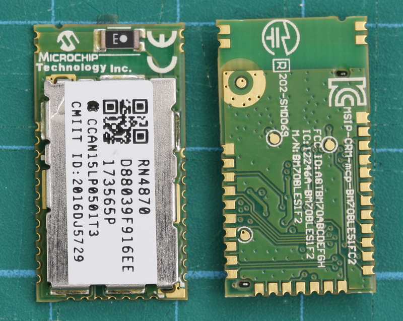
 The RN4870/1 is a small (only 12mm wide) BLE module from Microchip. What makes this a little bit special (when compared to modules like the HM-10) are the advanced features that allow you to create your own services and characteristics. This opens up true BLE functionality. It has been available for a while now and I am surprised it is not more popular in the hobby area.
The RN4870 is very different to common hobbyist modules like the HM-10, AT-09, and BT05 and if this is all you have used you may need a refresher on BLE. Especially if you want to use your own services and characteristics.
RN4870/1 Features
- Fully Qualified Bluetooth 5.0
- Low Energy Module
- Certified to FCC, IC, CE, KCC, NCC and SRRC
- On-Board Bluetooth 5.0 Low Energy Stack
- ASCII Command Interface API over UART
- Scripting Engine for Hostless Operation
- Beacon Private Service for Beacon Services
- UART Transparent Service for Serial Data
- Over The Air Remote Configuration
The RN48709/1 is configured using ascii commands similar to other BT modules. The main difference s that the The RN48709/1 has it’s own set of unique commands and does not use AT style commands. It also has a mini programming or scripting language built in. This means, depending on what you want to do, you may not need a MCU like the Arduino, the RN48709/1 can be used stand alone.
The UART Transparent Service for Serial Data allows an easy way to link 2 modules together. This can be considered a serial cable replacement, however, if this is all you need you may be better suited with the HM-05/06 or HM-10.
The The RN48709/1 has full BLE 5.0 functionality:
- Secure AES128 Encryption
- GAP, GATT, SM, L2CAP and Integrated Public Profiles
- User Can Create up to Five Public and Four Private Services
- Software Configurable Role as Peripheral or Central and Client or Server
- Keyboard I/O Authentication
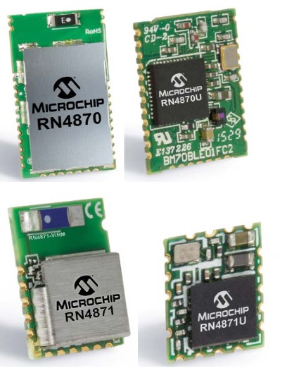
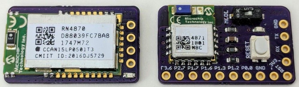
The RN4870/1 is available is a few different sizes/configurations. With shielding, without shielding, with antenna, without antenna, all pins available, only basic pins available.
The ones I have are the RN4870-V/RM118 version. With antenna and all pins available.
These modules are more expensive that the common hobbyist modules like the HM-10 but they far more advanced, well supported with full data sheets and a user forum. Most questions, if not all, will have already been answered on the forum.
Microchip official information
RN4870 product overview
User guide, data sheet, firmwares and update tool. Same page as above, click the Documents tab and scroll down.
Technical details. This is a website with lots of details. Use the menu on the left.
Getting Started
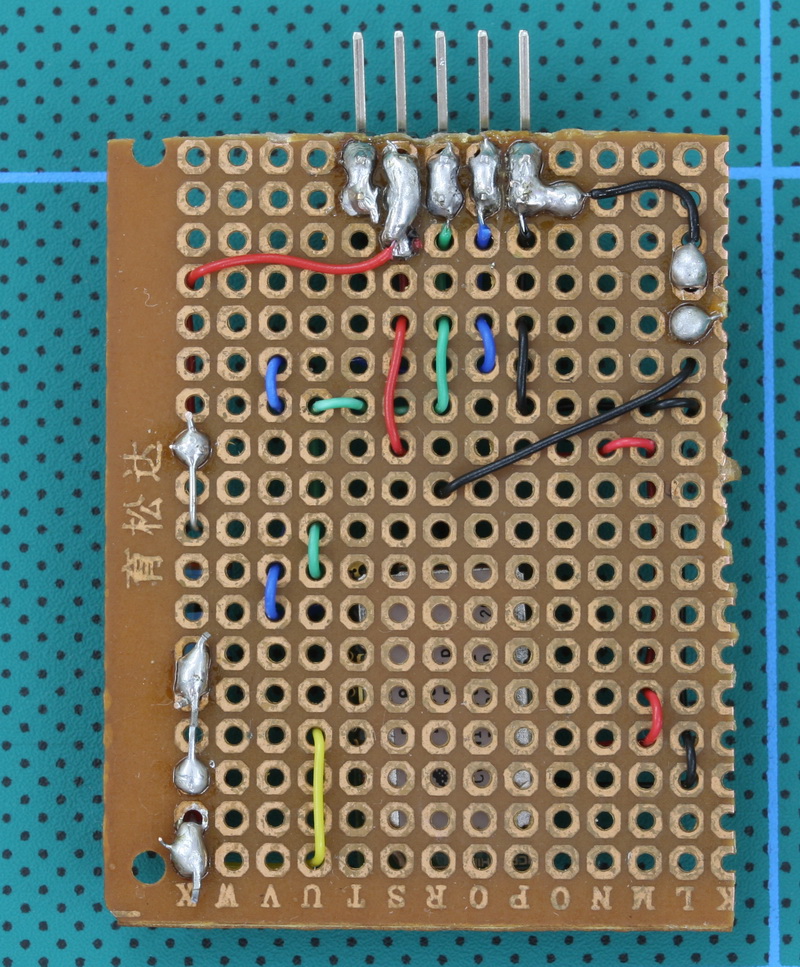
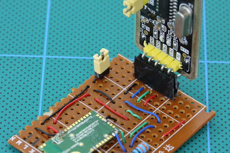
The RX4870/1 is a very small SMD board which makes it a little difficult for hobbyists. A basic breakout board can be built if you have fairly steady hands. Here is my rather lack lustre attempt. I mounted the module upside down so that I still have access to the pads should I need to add more connections later.
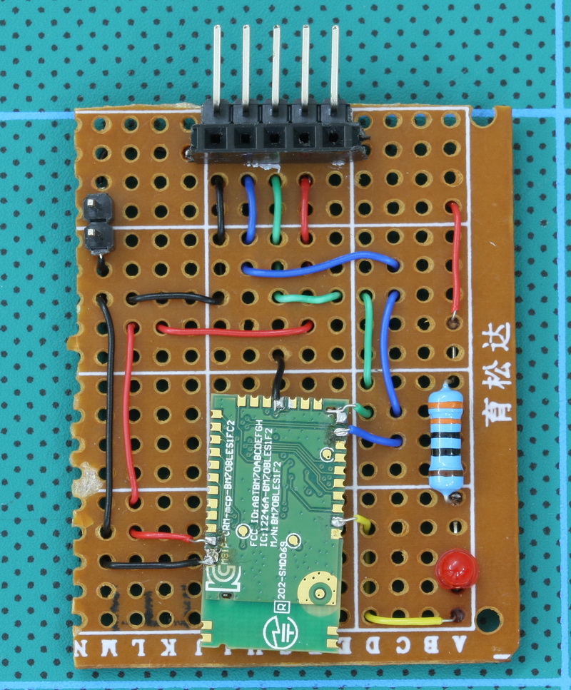
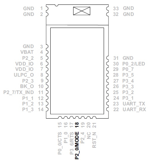
The jumper is connected between pin 18/P2_0 and GND. With pin 18 brought to GND when the modules start they enter programming mode. This allows you to update the firmware. The jumper is a simple way of connecting pin 18 to GND.
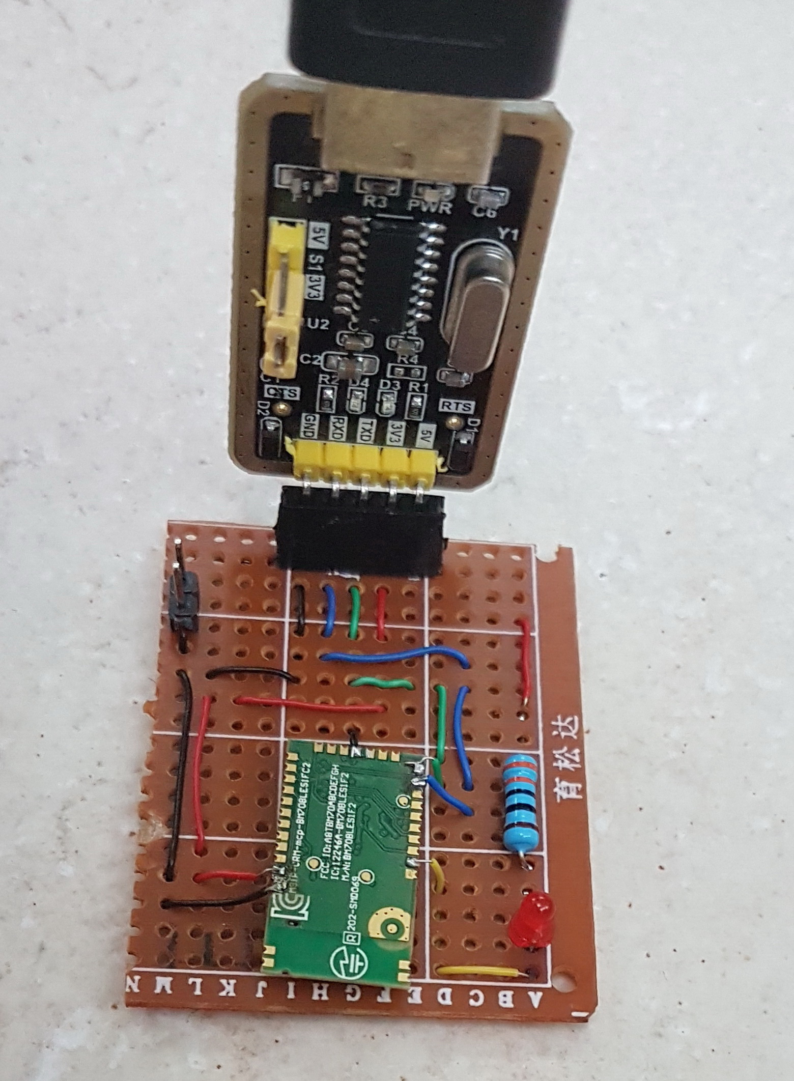 The connections are arranged to match the usb/serial adaptor I am using.
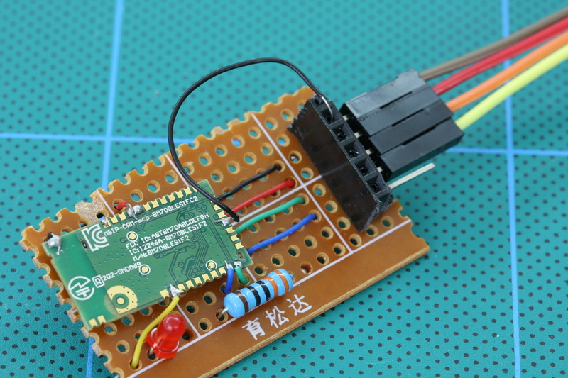
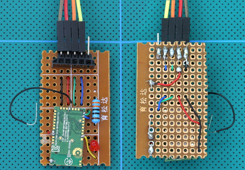 Here is a second board which is slightly smaller. This one has a wire connected to the programming pin. I simply connect the wire to GND when I want to enter programming mode. The extra pin/socket on the end is not used.
You will notice that I used different pins for GND and VCC from the RN4870. This allowed me to use 2 pads to solder the wires which made life a little easier.
I am surprised that there are not more pre-made breakout boards for this module. The only one I can find is the RN4870/1 Click from MikroElektronika.
Jon Raymond contacted me to say he has created his own breakout boards (which look very nice) and is hoping to release the designs at some point. See Jon’s Twitter feed for pictures.
David Ashmore kindly shared the Gerber files for an breakout/adapter board he created
quote from David:
the boards were designed from the datasheet and implement the 2 pins for the i2c and the 2 for the I/O. it had an 8 pin SIP interface.
Pins & Basic Circuit
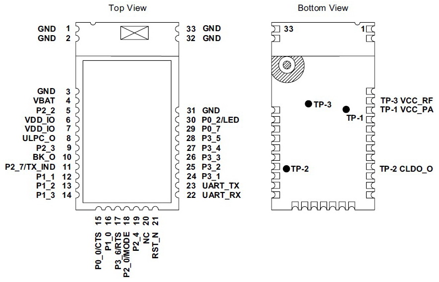
The pins we are initially interested in are:
Pin 3 – GND
Pin 4 – VBAT (3.3v vcc in)
Pin 23 – UART_TX
Pin 22 – UART_RX
These are all you need to use the module but it is a good idea to add a LED to Pin 30 so you know if it is on or not.
Remember that RN4870 RX goes to usb adaptor TX and RN4870 TX does to usb adpater RX.
The data sheet has full details for the other pins.
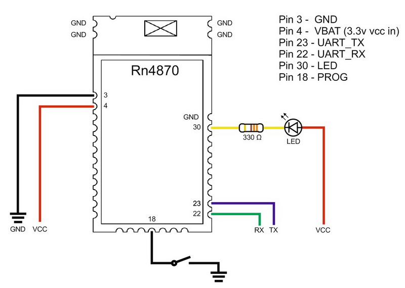
This is a corrected diagram. The previous diagram had the LED on the wrong pin and wired backwards…
New modules have a basic beacon set up and we can use this to test if the module is working or not. For this just add vcc and GND. Remember these are 3.3v devices so use 3.3v not 5v.
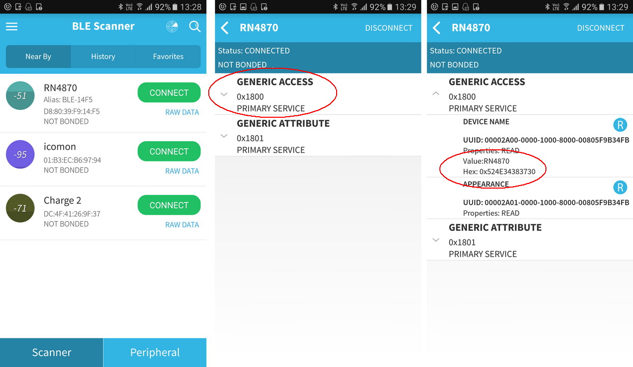
Power the module, then use a BLE scanner app to find the beacon. Here I am using Android BLE Scanner by Bluepixel Technologies LLP but there are many similar apps.
Open the app, you should see the RN4870 (it will not have the same name), connect and the LED should change to 2 quick blinks every second.
– Open the first characteristic (Generic Access 0x1800, this is the device name)
– Read the characteristic data by clicking the small R icon. You should get the name again.
Now we know it is working we can try talking to it through a serial terminal program, something like Tera Term or the Arduino IDE.
Talking to the RN4870/1
To talk to the RN4870/1 we need a usb to serial adaptor. I am using this one but other 3.3v versions will work. Make sure it is 3.3v. At a push you could use a spare Arduino but I don’t go in to this here.
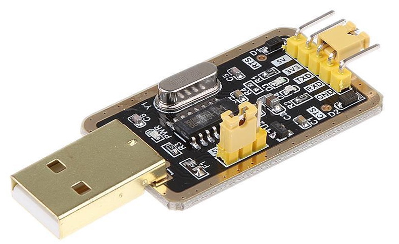 Here is a adapter I am using. 3.3v or 5v can be selected.
Connect the RN4870 to the usb adapter and connect to a PC, note that I am using Windows 7, this will give you a COM port. Mine is COM5. Yours will be different.
For the first few examples I am using the Arduino IDE. The Arduino IDE does not have local echo (it does not display what you have entered) but you can turn on local echo in the RN4870 with the “+” command if you wish. Use the “+” command after entering data mode.
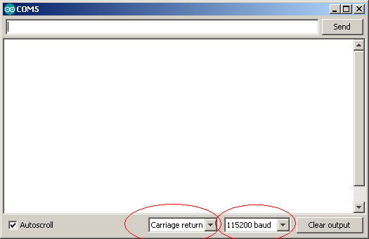 If you check the data sheet you see that it has a default baud rate of 115200 and all commands require a carriage return CR character (\r).
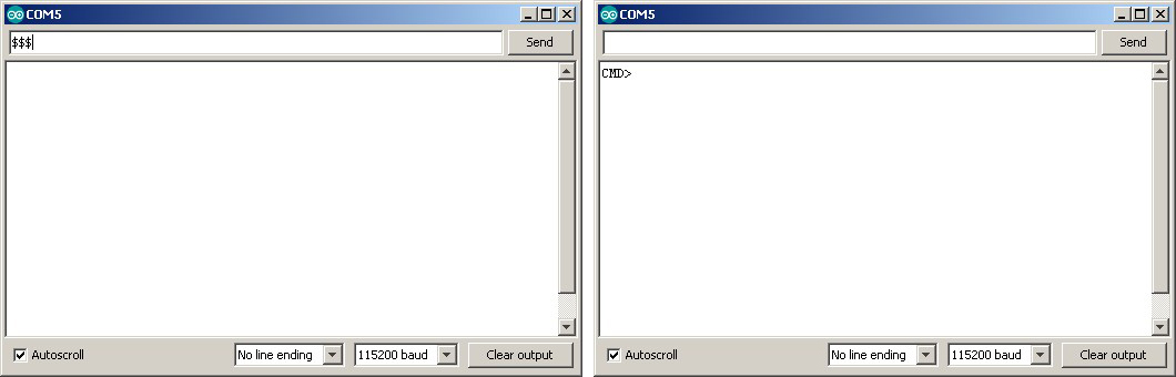
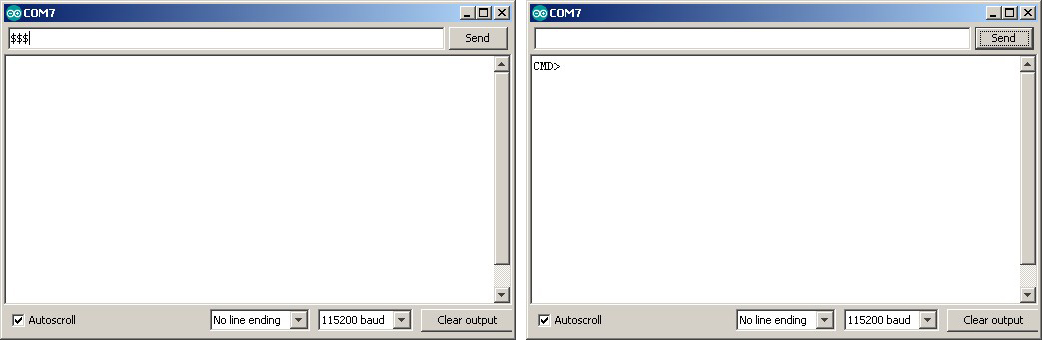
The RN4870 can operate in data mode or command mode. It is in data mode by default so we need to change to command mode using the “$$$” command. Small caveat though, Microchip do not class “$$$” as a command and it only works when there is no line end character. This really should be stated in the data sheet. So change the line endings to “No line ending” and enter $$$:
If the world loves you, or even likes you just a little bit, you will get a “CMD>” reply.
To return to data mode use “—\r”. This is 3 dash or minus characters + CR.
Now change the line endings back.
![]()
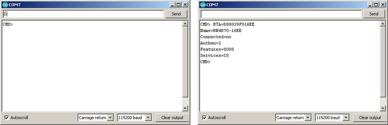
There are a few commands that return data (these are called GET commands). One is the “D” command and another is “V”. “D” returns information about the device and “V: returns the firmware version.
“D” command
The “D” command returns device information:
– Device MAC Address
– The random address (if a random address is used)
– Device Name
– Connected Device MAC address
– Authentication Method
– Device Features as set by the “SR” command
– Server Services
– The fixed pin code (if one is being used)
“V” command
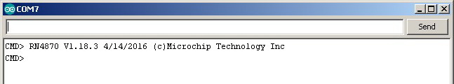
The “V” command returns the firmware version.
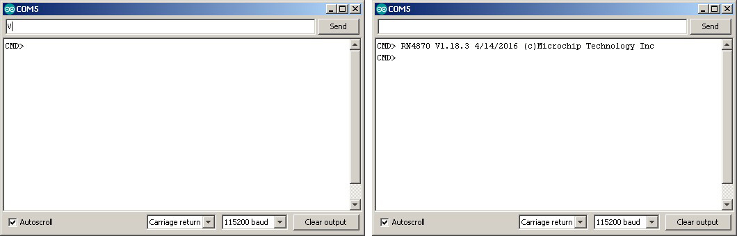
Here you can see that the modules I have are using firmware V1.18.3. This is not the latest and I will look at updating it later. The latest firmware, at the time of writing, is v1.28.3 v1.30.
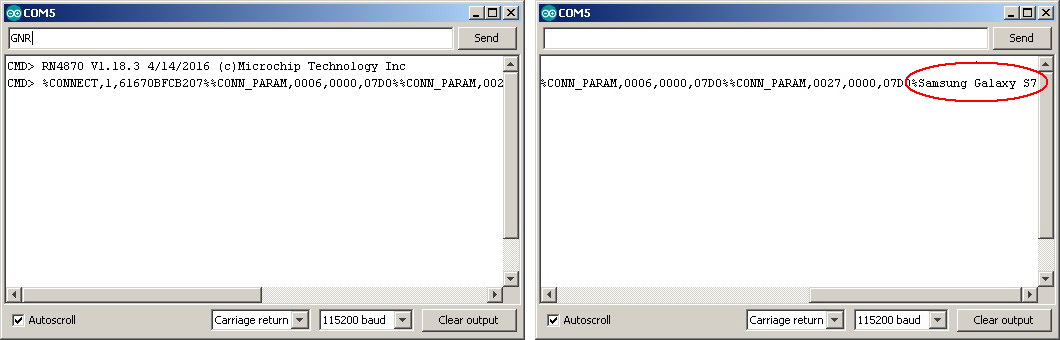
“GNR” command
“GNR” gets the name of a connected device. Of course, for this to work the module has to be connected to something. With the serial monitor still open. Use the BLE scanner app to connect to the RN4870.
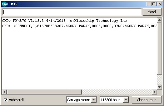
When the module connects it sends the connection details to the serial monitor:
Now we have a connection we can get the name of the connected device with “GNR”
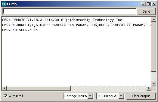
When you break the connection, the RN4870 outputs a “%DISCONNECT%” message.
For a full list of the GET commands see the data sheet.
First Communications
Please note I am using a module with 1.30 firmware.
Firmware 1.30 comes with a set of default services and characteristics built in and we can use these to try out making a connection. I am keeping it simple and using the Arduino IDE with the same serial adapter and BLE Android app as above. The RN4870 is on and in data mode.
In the Arduino IDE, select the correct COM port and open the serial monitor.
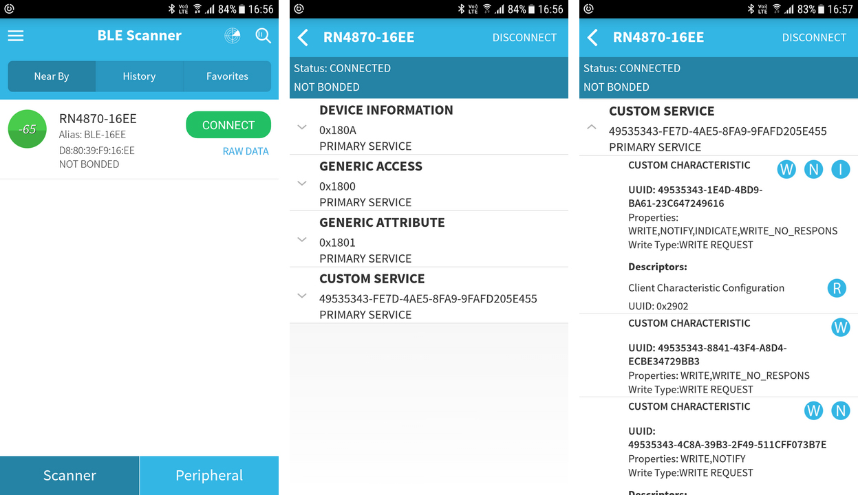
Start the BLE Scanner app, if it does not automatically start scanning, hit the Scanner button at the bottom. You should see the RN4870 appear in the list.
Hit the CONNECT button, after the connection is made, select the Custom Serice
In the serial monitor you should see the connection message
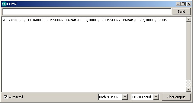
We can now try sending data to the serial monitor.
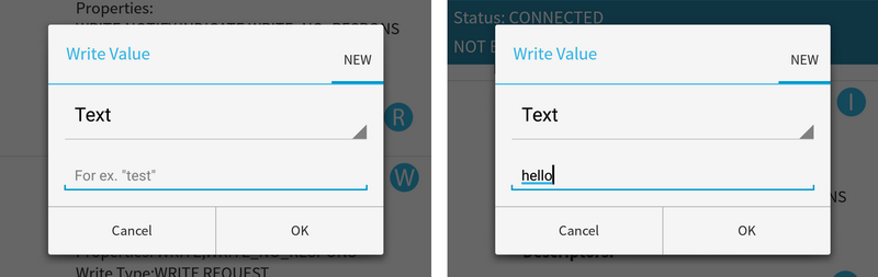
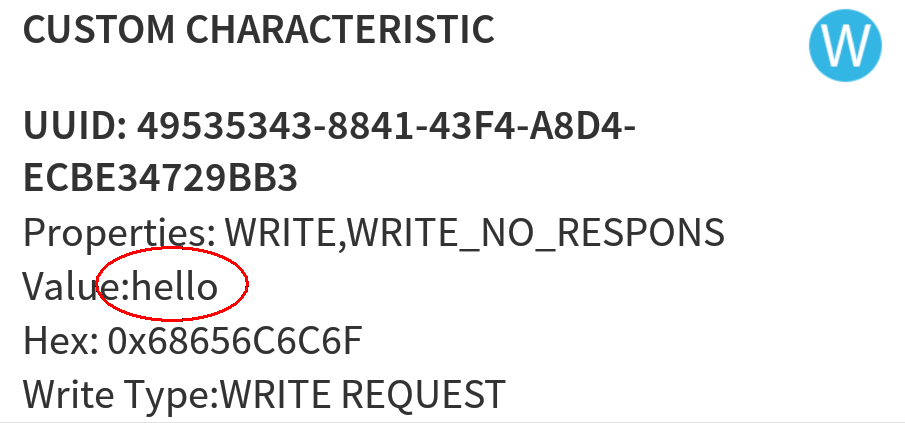
For the the custom characteristic 49535343-8841-43F4-A8D4-ECBE34729BB3, hit the ![]() write button, a text input box should appear, enter “hello” and click OK
write button, a text input box should appear, enter “hello” and click OK
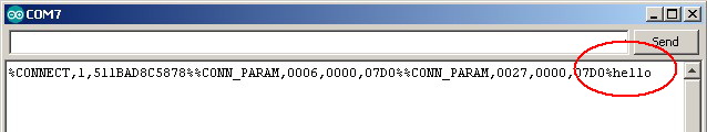
The value of the characteristic changes to hello and you should see hello in the serial monitor
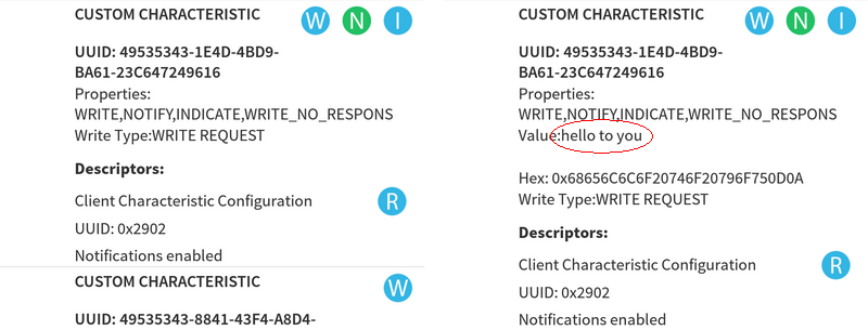
The RN4870 receives data via the 49535343-1E4D-4BD9-BA61-23C647249616 characteristic.
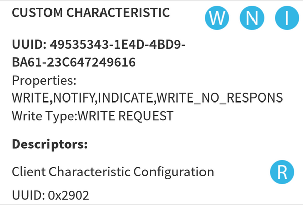
Click the ![]() notification button to turn notifications on (The indicate button also works).
notification button to turn notifications on (The indicate button also works).
In the serial monitor enter “hello to you” and click send and “hello to you” should magically appear in the characteristic.
Notify or Indicate?
In the above example I use Notify to confirm when data has been received but you can use either Notify or Indicate so what’s the difference? Notify does not need an acknowledgement, Indicate does. This makes Notify a little faster but less reliable. Notify also allows for constant data flow whereas Indicate has to wait after each piece of data for the acknowledgement before it can send the next piece.
Notify
Here is some data, get it while you can.
Here is some data, get it while you can.
Here is some data, get it while you can.
Here is some data, get it while you can.
Indicate
Here is some data, have you got it yet? wait, wait… Reply “I have it” received now I can send the next data.
Here is some more data, have you got it yet? wait, wait… Reply “I have it” received now I can send the next data.
Here is some more data, have you got it yet? wait, wait… Reply “I have it” received now I can send the next data.
Here is some more data, have you got it yet? wait, wait… Reply “I have it” received now I can send the next data.
I like to think the modules have conversations with each other.
Connecting Two RN4870 Modules Together
The RN4870s have a transparent UART layer built in. This means it is easy to get them connected and start sending data. This is very similar to how the HM-10s (and similar modules) work, and, if this is all you need you might as well go with HM-10s. They are cheaper and come on hobbyist friendly breakout boards.
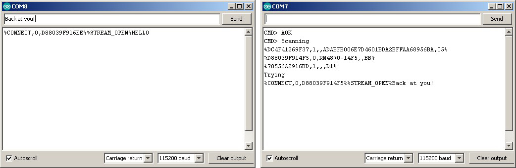
To get started I am using modules connected to the same computer with usb to serial adaptors. The same ones as above. One of the modules is on COM 7 and the other is on COM 8. I am using the module on COM 7 to initiate the connection. Everything is manual. The modules I am using have firmware 1.30.
Creating a connection is straight forward as long as you have the MAC address of the remote module. If you have the address you can simple use the connect to mac address command. If you don’t have the address then you can scan. Scanning returns the mac address and the name of found modules. The address for the device I want to connect to is D88039F914F5 but I’ll pretend I don’t know it.
On the main device, enter command mode with “$$$” (no EOL characters).
Enter SS,C0 to enable the UART transparent service.
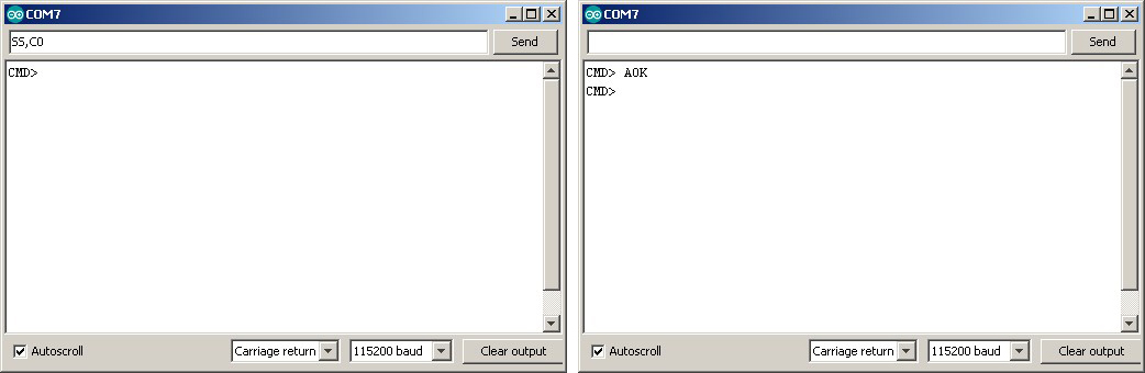
Enter F to start a scan
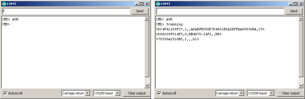
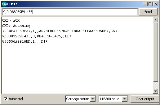
I am looking for the module named RN4870. It is the second one and its mac address is D88039F914F5. To connect use the Connect “C” command. The “C” command expects 2 parameters;
1 – the type of address, 0 or 1). 0 for public address, 1 for private address.
2 – the mac address
So, to connect I use “C,0,D88039F914F5”
If the connection is successful you will get connection messages in both serial monitors.
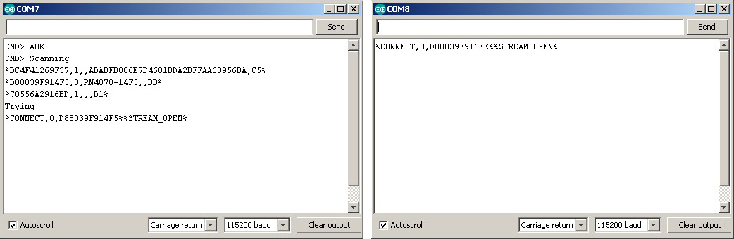
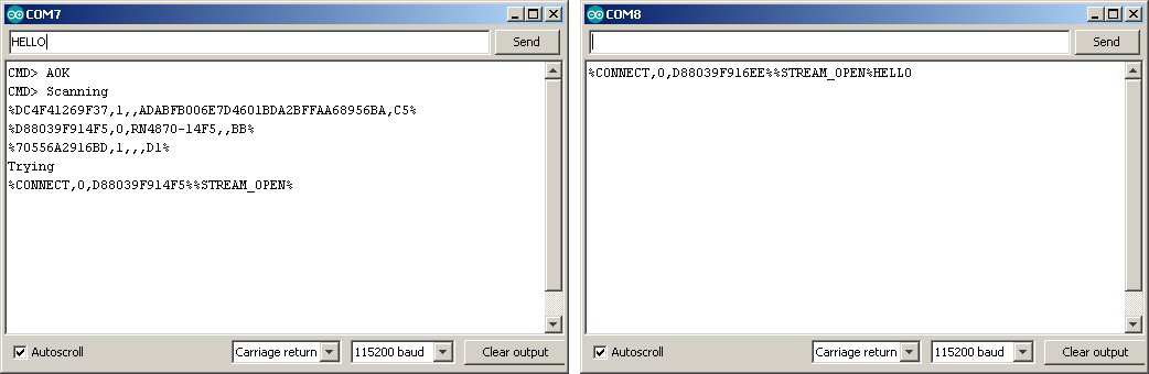
And once the connection is made the modules can talk to each other
Updating the Firmware
The official Microchip information only covers updating the firmware when using the PICtail development board but it is fairly easy to update using just the RN4870 module. You will need:
– A RN4870
– A USB to serial adaptor
– The isUpdate.exe file
– The firmware to upload (4 files)
You will also need to know the COM port the usb to serial adaptor is using. In my case it is COM 7.
The update tool and the firmware can be downloaded from the Microchip RN4870 page. Click the Documents tab. You can download the data sheet and user guide from the same page.
To put the RN4870 in to programming mode we need to bring pin P2_0 low during boot. P2_0 is the bottom centre pin.
On the larger breakout board, closing the jumper connects pin P2_0 the GND.
On the smaller board, the wire is used to connect P2_0 to GND. This is a very lazy solution and not really recommended. I have killed more than one Arduino because of this technique. It is easy to short something that shouldn’t be shorted.
To update
I am updating from firmware 1.18.3 to 1.30. FW 1.30 was released on May 4th, 2018.
Only one program can connect to a COM port at a time so if you have a serial monitor open, close it. Then:
– Remove power from the module,
– Connect P2_0 to GND and
– Re-power the RN4870.
Although there is information online that the LED is solid on, for me the LED is off. Apparently, if you connect the LED the right way round it works correctly, it is solid on when the module is in programming mode. Who Knew? Me if I’d read the data sheet correctly. Thanks to Jon Raymond for pointing this out.
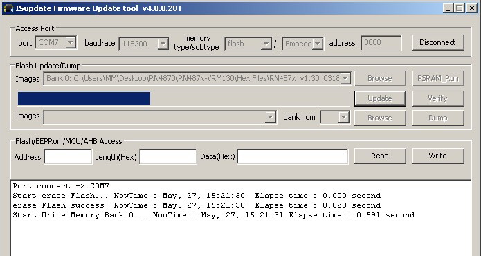
Open the isUpdate.exe file (Installation is not required).
– Set the COM port (mine is COM 7)
– Set the baud rate to 115200
– Set memory type/subtype to flash and Embedded Flash (or Embedded F)
– Set address to 0000
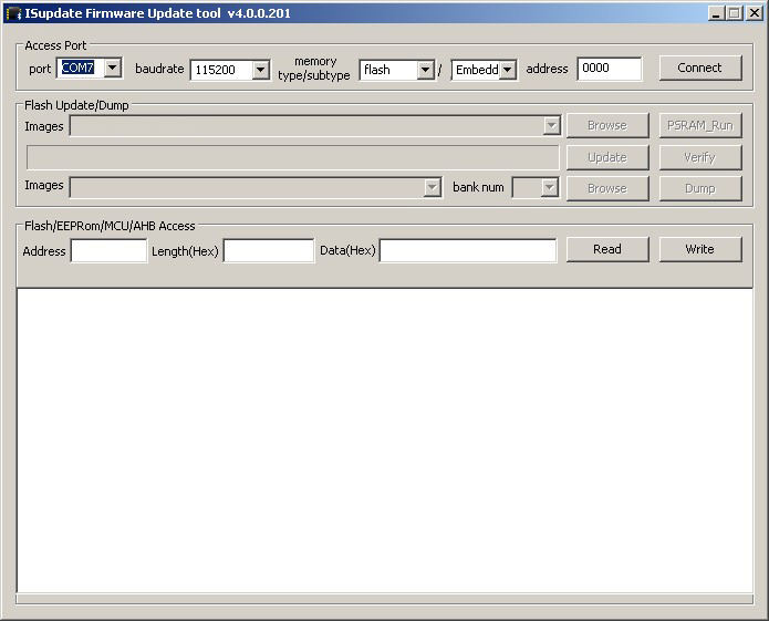
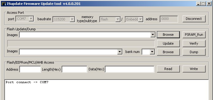
Click Connect. If the module connects you get a “Port connect -> COM7 message” (or whatever port you are using) and the programming buttons become active.
Now click the Flash Update/Browse -> Images, Browse button and select the 4 firmware files. You can select all 4 files in one go.
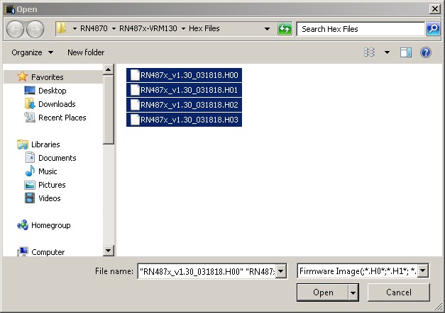
And then click Update. If everything is fine the update should start.
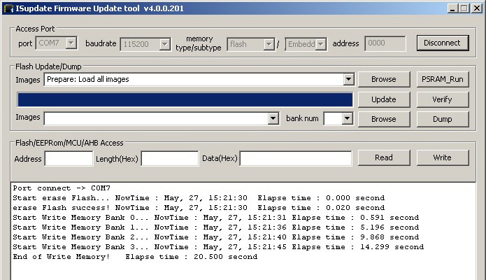
The “End of Write Memory” message indicates it’s finished and that’s it.
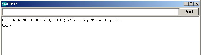
We can now check we have the new firmware:
– Close the isUpdate app or click the Disconnect button to release the COM port.
– Power off the RN4870
– Remove the programming wire
– Restart the module (the LED should be on)
– Open the serial monitor
– Enter command mode with “$$$” (remember no EOL characters)
– Check the firmware with the “V” command (requires the CR EOL character).
Release notes are included with all firmwares but the notes only include the changes for the latest version (no history). If, like me, you are jumping a few versions you will need to check the release notes for each firmware version to know what all the changes are.
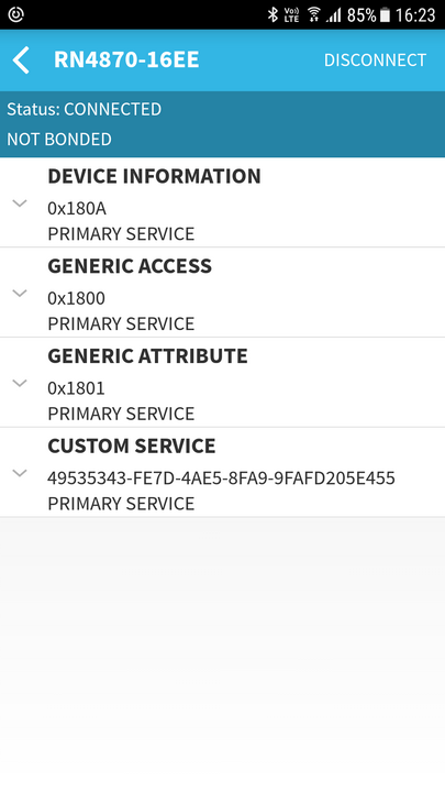 After updating, use a BLE scanner app to check the default services and characteristics.
Thanks, helpful.
I enjoyed this article so much I bought a mikroBUS RN4871 click board https://www.mikroe.com/rn4871-click to experiment. Looking forward to reading further posts on RN4870/1 chip
Thanks for the article. Have you seen Bluetooth network 1 master to many slaves one-way communication? Best regards
The RN devices only support single connections. For a piconet you would need to use devices like the BTLC1000 and SAMB11. These support up to 8 simultaneous connections.
Thanks Martyn for the good work. I was actually thinking a single Raspberry Pi 3 B+ as master with 5 slaves each mikroBUS RN4871. Slaves only need to receive data so I guess each RN4871 is single connection. It’s not going to work, it is? Perhaps you are wondering why mixing Raspberry Pi and Arduino/Teensy over bluetooth but I don’t have a choice as bluetooth slaves must be mikroBUS “click” for Teensy while commands are provided by a very specific HAT master hosted on Raspberry Pi. Any thoughts would be greatly appreciated as I am a bit stuck with these requirements. Many thanks. All the best
I don’t know much about the Raspberry Pis but I can’t see why this wouldn’t work.
The only thing I can’t determine is if the Pi can have more than 1 Bluetooth connection at a time. If not you would need to connect to each node in turn.
Hi Martyn,
I have RN4871. I followed the all sentences from your article.
I have a connection between reset and GND via 1uf electrolytic capacitor. Also, there is 4.7kohm between reset and 3.3V. I left the P2_0 pin idle. I connected to USB TTL module. And I try to make communication by tera term.
My problem is that the device is reboot by itself without any reason simultaneously. Sometimes I write $$$ then it enters the CMD mode. Also, I can write V or D, but it reboots again.
I couldn’t find any reason. I used ceramic cap for the 3.3V and GND.
Can you help me.
Best Regards,
do you have a stable power supply that can deliver enough current?
I gave power from arduino uno, nucleo 32 and usb uart ttl board.
I have been reading all your posts on the HC-05, HC-06 and now the RN4870. I have a piece of electronics that uses an HC-06 to link to Android apps and Windows software. But it will not of course link to anything iOS. Is it possible to set up an Arduino with an HC-05 as a master and link to the HC-06, and then pass the data thru to the RN4870 so that iOS can at least recognize the RN4870.
Yes. The Arduino would just act like a relay station very similar to the serial pass through sketch above. You would simply connect the electronic device to the hardware serial and have the Arduino relay whatever is received to the software serial. This can work well if hardware serial is available, especially if the device uses a high baud rate like 115200 or higher (software serials do not handle fast baud rates well).
If the device uses a lower baud rate to connect to the HC-06 then it could also be done using 2 implementations of software serial. In this case I would recommend using different libraries such as SoftwareSerial + AltSoftSerial so that both can be active at the same time.
A reliable solution would depend on how much data is being transmitted and fast it needs to be sent. BT classic has a much faster throughput than BLE and handles large volume data much better.
If you have access to the device it may be possible to replace the HC-06 with a BLE module such as the HM-10 or RN4870/1or any module that talks UART. This assumes the device is not controlling the HC-06 and the HC06 is simply acting as a serial bridge.
Thank you for the helpful info and the quick reply.
Hi Martyn,
I wish I could replace the HC-06 on the device, but it is not doable. That is why I am looking at this “relay” workaround. So if I understand correctly I can have both the HC-05 (master) and the RN4870 wired to the Arduino. Use the HC-05 to link to the HC-06 on my device, and then have the RN4870 link to an app on an iOS item (Ipad, Iphone).
Hello Martyn,
I am getting started with Bluetooth BLE, and am following your website. I have built a simple breakout board for RN4870 module with a USB to UART interface. I have worked my way through your instructions to about halfway, stopping at “Connecting Two RN4870 Modules Together”, Everything works fine, so thank you for excellent guidance.
I have also followed the instructions in the
Microchip RN4870-PICtail-UserGuide.pdf
using the same breakout board with some pots, LED, switch, added instead of the PICtail board. Again, everything works as expected, including communicating with BLESensorApp on an Android smartphone.
On my Windows 10 PC I have used the Arduino IDE as you suggest, and also the CoolTerm terminal emulator. They both work fine.
I would now like to move on to my real objective, which is to connect a digital temperature sensor to my breakout board and capture the readings on my PC.
I do not foresee any difficulties at the board end, as I am well able to deal with the hardware, and expect to be able to program the RN4870 as required ( Or alternatively to write a script ).
My problem is what to do at the Windows PC end. Neither of above terminal emulators appears to meet my objective, i.e. to capture temperature readings and present them on screen, and also to save them to a file. I should mention that I plan to capture readings say every 15 mins over a whole day, and save them together with time and date stamp.
I guess a program could be written in Visual Basic to do this, but my knowledge of VB is very limited. My feeling is that something like this should already exist, perhaps a Windows version of the BLESensorApp, but I havn’t managed to find anything.
Can you offer any advice or point me towards a suitable program?
Thanks and best regards, Ken.
Hi Ken,
I replied by email by mistake and not sure if you received.
Unfortunately I don’t have anything to recommend. I would suggest joining the Microchip forum (if not already a member) and ask in the Bluetooth section. You could also try on other forums like stackoverflow
A while ago I started to look for a suitable app but got side tracked with work, decided to create an Android app and never looked at VB again. Visual Basic (or C or C++) should not be too hard for you and a google search brings up quite few resources about the Windows BLE services. Not sure how complex using BLE on Windows is though. I suppose it depends on how much of the work the services do for you.
Hello again,
Apologies, I missed some key info from my earlier comment. My PC connects with Bluetooth with a BLED112 dongle, and I use the Bluegiga BLE GUI. But this also does not seem to meet my needs. In fact, on the Silicon Labs Bluetooth Forum it states:
“If you are looking for a plug&play BLE dongle that will make your PC BLE capable then BLED112 is not such a product”.
So perhaps I first need to find another BLE dongle?
It is highly unlikely there is an existing app that will do exactly what you want but Silicon Labs do have and SDK for the dongle. Have a look on the Silicon Labs site. A quick google gave me this https://www.silabs.com/community/wireless/bluetooth/forum.topic.html/ble_desktop_applicat-hg4X and this https://www.silabs.com/products/development-tools/software/bluegiga-bluetooth-smart-software-stack
Martyn- Thanks you for another excellent article on Bluetooth modules. I would appreciate your comments regarding the appropriateness of the RN4871 for my first Bluetooth project. I’m considering using the RN4871 module as serial passthru device to transfer data from an old serial instrument (TX only, no flow control) to a tablet.
Question: Once the 4871 is configured via the UART interface (no scripting allowed) and removed from the programming device (PC via Serial), will the 4871 retain functionality to perform as a “stand alone” serial pass through device?
I’ve ordered and received HM-10 devices and I have found out that I simply cannot operate within the chaotic environment this device has generated.
Regards and thanks for your efforts
You don’t say which tablet but if it is Andriod I feel you would be better with the HC-05 or HC-06. These use the simpler BT SSP profile. They don’t work with Apples IOS though.
To answer your question. Yes, once set up the RN4871 remembers the settings.
What was the issue with the HM-10s? I have moved away from these now but in the past I used them in some fairly wifi polluted environments without too much issue. The only thing I really noticed was that the distance they could be used was reduced.
Without really knowing, I suspect if you have issues with the HM-10 you are likely going to have issues with other BLE modules.
Martyn,
Thank you for the response. I’ve ordered HM-10’s from multiple sources and have received (mostly) counterfeits. It takes a few hours of sleuthing to determine exactly which modules have been sent, and even with that information the command set (usually) doesn’t agree with the data sheet (if there is one). Additionally, emails to HM regarding certified suppliers go unanswered. I’m investigating the RN4871 solely because of the EXTENSIVE data sheet, and availability via a known distribution network.
Hello Martyn,
Yes, I did receive your email — many thanks and apologies for rather tardy reply to it. Meanwhile, I have bought another dongle, the ASUS USB-BT400 USB Adapter. I picked this one because it seems to be generally recommended as reliable and problem-free. I have installed it and it appears to work properly. I can pair it with my Android phone, and transfer files via it. I can also pair it with my board with RN4870, and I can see from the terminal emulator that the last program I installed for the PICtail board is still running correctly (ie reading sensor info and displaying that on the BLE app on the phone).
But I am again stuck at this point, and have no clue about how to get the sensor data on to my PC. So I will follow up on the Silabs links you give, and also try the Microchip forum, although my past experience with that is not very good.
Thanks again for your help, and excellent article. Ken.
I bonded (2) Microchip RN4870 BLE FW V1.3 modules, but found that they can disconnect on their own (even the Microchip Eng told me to code into the Features to “reboot” upon disconnect, which I think confirms that they have this bug).
In looking at RN4870 internet posts, I found other people having problems with these modules, and someone recommended the Silicon Labs (purchased AckMe) AMS002.
I purchased 2 of the Bream (AMS002) development boards from Digikey and they seem to work well, but I don’t see yet how to pair them yet (there is an unpair command, so there should be a pairing command).
My question is, for a serial UART application, only needing to transfer small amounts of serial data back, and forth, what modules would you recommend?
(2) HC-05’s, HC-05 / 06, SH-HC-08’s, HM10’s, HM-12, HM-13, or HM-17, or another?
If power is not a concern then Bluetooth Classic SSP such as the HM-05/06. But if you go this route make sure you get good modules like the ones from Waven. These have a good firmware and are well supported.
If power is a concern look at BLE modules sans breakout board. I’ve had good results using the HM-11. Good connections and fairly low power use. There are better options if low power consumption is critical though.
Hello Martyn,
Thank you. It is a very informative post. Have you tested the physical communication distance between module and phone? As far as I could remember, this module has a very poor signal strength. The smaller RN4871 is even worse. There is someone facing the same issue as well.
https://www.microchip.com/forums/m980164.aspx
I haven’t done any distance / signal strength tests but like you I am starting to find complaints online. Don’t know how much these reflect the real situation though. If it was really poor I would expect a lot more complaints than there are.
Hello Martyn,
I followed your instructions with a bit of variation using an adruino as a usb to serial port and am having some troubles. I get no communication from the board and any commands i send get no response from my computer. The led flashes the correct sequences when i try to connect via bluetooth (cant communicate there either) or ground pin 18 so i assume the board is working correctly and im just unable to communicate with it. i also tried reflashing the board but the connection failed using isupdate.exe. is there an extra step to connect this board using an arduino? i did the standard ground to reset on the arduino and same tx->rx and rx->tx but still get no response.
It’s not clear how you are using the Arduino. Are you removing the AVR and using it as a serial to usb or are you using it with a serial pass thru sketch?
Hello Martyn –
This is a fantastic tutorial; thank you so much. It has allowed me to move forward in my attempts to prototype a BLE peripheral.
I’ve had success following this tutorial, communicating between an iPhone and an RN4871. Oddly, the same attempts fail between an Android phone and the same RN4871. In both cases, I use the Nordic utility; “nRF Connect” on the phone.
Below is the sequence of status events on the RN4871 I see in both cases. It seems to require many attempts before a connection is successfully achieved. What I find particularly mysterious is the difference of the 2nd parameter in the %CONNECT% status. When the iPhone is trying to connect, it is always ‘1’. When the Android phone is trying to connect, it is always ‘0’. I can’t find an adequate reference to explain this.
Would you have any insight on this that you could share? Thank you again!
-Aaron
RN4871 status during iPhone connect (succeeds):
CMD>
%CONNECT,1,536FF9FDD185%
%DISCONNECT%
%CONNECT,1,536FF9FDD185%
%DISCONNECT%
(about 8 or 9 repeated connect/disconnect pairs)
%CONNECT,1,536FF9FDD185%
(no disconnect !)
RN871 status during Android connect (fails):
CMD>
%CONNECT,0,806C1B93ACF9%
%DISCONNECT%
%CONNECT,0,806C1B93ACF9%
%DISCONNECT%
(about 3 or 4 repeated connect/disconnect pairs)
%CONNECT,0,806C1B93ACF9%
%DISCONNECT%
Please disregard the previous question. I determined the problem. My RN4871 proto-board had power supply problems. Once I fixed that, the connections are quick and solid, from iOS _and_ Android.
Thanks again.
Thanks for posting back.
Hi Martyn,
I’m trying to use the RN4871 connected to a temperature sensor to transmit the temperature values in adverting payloads. However I don’t know how to take my variable or the analogue input and add it to the advertisement packet.
In the User guide I’ve looked at the example code under 2.6.20 and seen how they enter a direct value but don’t know if it’s possible to put the variable name there or the analogue input. My aim is to have the module running off the built in script as it seems like quite a simple process.
Any help would be greatly appreciated.
Sam
Hi, did you manage to get something out of that idea? I’ve got similar plans but the datasheet is not helping much on how to set this.
regards.
Hi Martyn,
Thanks for the description. I had a play with ~ 20 of RN4871 modules and found them horrible. They hang continuously, factory reset zeroed mac in 2 of the units and 2 never properly communicated. Horror! Do you know any other alternative in the smallest form-factor?
Hi, this is a really old post I know, but I’ve seen some doc on the net that says the latest firmware V1.40 fixes the bug with zeroing the mac address.
I found power supply to my unit was critical. I killed one. Then on another I put a 10uF tantalum at the pins. I also used a 10K pullup on RST, and took the CTS pin low. This fixed my problem.
Hope it (belatedly) helps.
All firmware revisions less the 1.30 are prone to being bricked (MAC = zero and other fatal states) during startup or other power supply transients. I have over 200 coin cell devices currently in operation and I have solved this issue as follows:
IN ORDER OF IMPORTANCE:
1). POWER MANAGEMENT CONTROLLER (reset holdoff timer)
2). 10uf at power pins
3). .1uf at power pins
Advice for prototyping:
DO use the Microchip PICTAIL board.
DO NOT use the CLICK BOARD as the Click board does NOT provide ANY power conditioning what so ever. MY CLICK boards came with v1.18 (certain death revision) AND did not inmplement any filter caps
on the CLICK BOARD even tho the cap was drawn on their schematic (certain death^2).
Best to all
Hey Martyn,
i try to work withe the rn4871 BLE. Over the scanner app i can send commands to the BLE modul. My next step is to create a App withe MIT App Inventor 2 but i have not enough know-how in App-programming. I search for a simple LED ON/OFF function. do you have some experience withe the combination of rn4871 and your own android app?
I don’t have anything for the rn4870/. There is a post that features the HM-10 and although the UUIDs will be different the process should be the same: https://www.martyncurrey.com/arduino-hm-10-and-app-inventor-2/
Hi Martyn,
Thanks for a great article. I am currently trying to use an ATMega128 to interface with the RN4871 (just sending characters from the micro serial port to the BLE module) instead of the Terminal program on a computer, however I can not seem to get it working. I am trying to enter command mode by just sending out three ‘$’ one after each other, and then wait for a reply on the Rx serial port on the mico, I thought I would be receiving the characters ‘C’ ‘M’ ‘D’ ‘>’ but I am not getting any response from the BLE module at all. Am I doing something wrong, or is a microcontroller just not suited for this purpose?
Again, thanks for a awesome article,
Sophie
try sending all three $ together and remember to not include line end characters.
If you have never received anything, data or commands, double check the connections, baud rates, etc.
Hi. Similar problems with 4871. I think it is very sensitive device to psu noise. I added a 10uF tantalum cap on the power pins, a 10k pullup on RST and CTS low.
Kind regards
Richard
I doesn’t appear that the John Raymond boards were ever released. There is another option that is less expensive than the Mikroe Click. You can find a bare radio breakout or USB / radio combo breakout at 1wattlabs (dot) com .
Hello
I’m trying to connect RN4871 with my laptop using DB-9 female cable to the USB connector. The pin configuration is as follows:
UART Rx = Pin 3
UART Tx = Pin 2
GND = Pin 5
Vbat = Pin 9
I looked at the serial terminal Desktop app and see corrupt data. Noting what makes sense. I even tried the same without connecting the Vbat to PIN 9. I still get the same result.
Note:
I scanned for the BLE device with the exact app you suggested and RN4871 dosen’t show up but the LED connected to the BLE module ON/OFF PIN doest turn ON. The power supply unit shows that its supplying 0.35A of current. I’m not sure why the unit is not showing up when I scan.
Is there something that I am missing?
Thanks
Double check you are using the correct pins. On the RN4871 I think the RX and TX pins are 7 and 8. On the RN4871U they are 4 and 5.
See the data sheet, page 4
http://ww1.microchip.com/downloads/en/DeviceDoc/RN4870-71-Bluetooth-Low-Energy-Module-Data-Sheet-DS50002489D.pdf
Hi Martyn
Thanks for your very helpful and instructive information, i have found it very useful in my own experiments. Did you get any other breakout boards for this device? i have developed a board for my own experiments and have created the gerber files etc. to have them constructed but have not yet got around to having them made as i am trying to make them up myself. if you or any of your readers can utilise them you are welcome to them.
Hello
I plan to make a walkie-talkie using RN4870. I send 8-bit sound samples and receive them using Transparent UART feature. But I can’t get the modules to send them continously. There are always some latencies and breaks during comunication. Have a look on the screenshot:
yellow – sample sound wave to PIC 18f66k80 ADC
green – data being send from PIC 18f66k80 to the RN4870
orange – data received by another RN4870 transmited to another PIC 18f66k80
blue – sample sound wave outputed by the receiver
How to fix this?
Have a nice weekend!
sorry I can’t help with this. You are likely to get help on the Microchip forums.
Hi, I have RN4871 connected to my Arduino (Teensy 3.2). I can send it commands and it seems fine.
The problem: I want to get the full 31 byte advertizing packet when I use the F command.
I have other beacons nearby (Kontakt) but I cannot find what to use to get the full advertizing packet. I desperately need to read the major, minor and RSSI.
Any help gratefully received.
kind regards
Richard
Hello, I am trying to connect my arduino uno to the RN4871 and still have problem can you plz share how did you connect it
also when i try to connect rx, tx of the arduino with the rx tx of the ble the module stop working
Awesome tutorial very informative and clear!
Could you please expand it with a few examples for Remote Command Mode?
The same example as you did with the HM-10 would be fantastic.
My only remaining question is: am I still able to send/receive UART data through the wireless bridge while simultaneously being able to toggle the GPIOs of the remote bluetooth module? If so, I think I will go with this alternative for OTA updates of my STM32411.
Thanks!
“I am surprised it is not more popular in the hobby area”
it’s 30 euros, dude
I get 2 HC05 for half the price