Introduction
Arduino Libraries
Parallel Interface: Getting Started with a JHD162A 16×2 display
I2C Interface: Getting Started with a J204A 20×4 display with I2C daughter board
Creating custom characters
Introduction
HD44780 compatible LCDs come in many shapes and sizes and two very common ones are the 16×2 and 20×4 characters. Although most screens come with a back light some do not. And although the original interface is parallel some screens come with an I2C adapter/daughter board pre attached (you can buy the I2C adapters separately).

Modules without a back light are not so common but it is still worth checking before you buy.
LCDs without the adaptor require 8 or 12 connections (see 4bit / 8bit below) and screens with the adaptor only need 4 connections. This makes the modules with the I2C adaptors far easier to wire up.
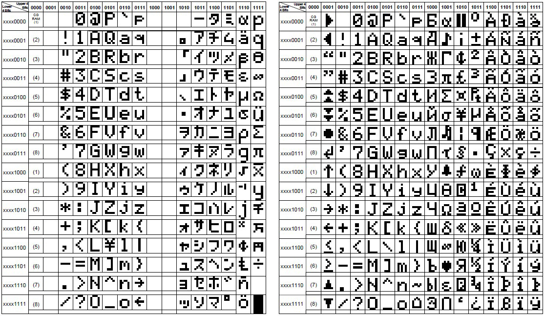
One final thing to look out for is the character set. HD44780s can have one of two different character sets; European or Asian.
Arduino Libraries
A key benefit of using a library is that we do not need to care that much about the technical details or timings when using the display. The library happily does all of this for us. On the downside, when different libraries try to use the same resources it can be very difficult to find the problem.
The Arduino IDE comes with a basic LiquidCrystal library pre installed. This works with parallel interfaces only. It works fine but has some limitations.
There are various other Character LCD libraries available. The two I use and recommend are NewLiquidCrystal by Francisco Malpartida and Bill Perry’s Extensible hd44780 LCD library.
NewLiquidCrystal is a collection of libraries that can handle almost all HD44780 compatible displays. It has a number of benefits over the default library, including the ability to handle screens with an I2C adapter. NewLiquidCrystal is a replacement for the default library so the default library has to be removed from the Arduino’s libraries folder.
Extensible hd44780 LCD library is still fairly new but seems to work well.
Download the NewLiquidCrystal library.
From the main wiki page click the Download link.
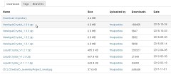
On the download page, download the latest version. Which at the time of writing this update is 1.3.4.
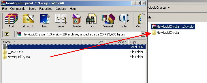
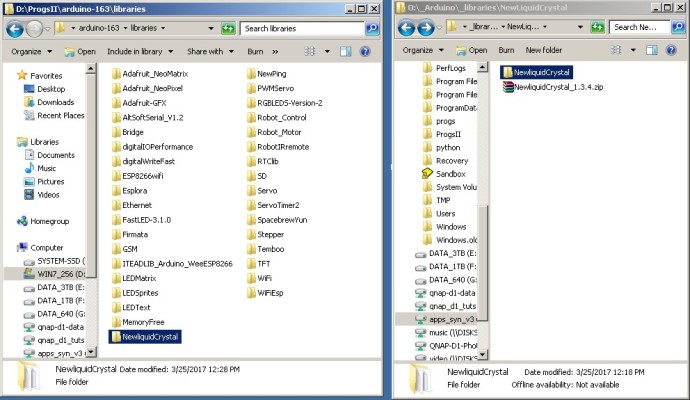
The download is a zip file. From inside the zip archive extract the NewLiquidCrystal folder
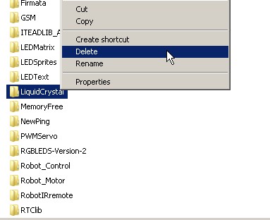
Go to your Arduino library folder and delete the default LiquidCrystal library
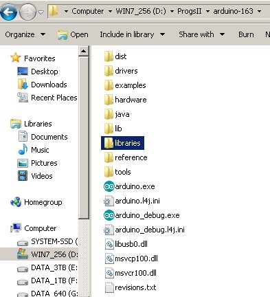
Then copy the NewLiquidCrytal library to the Arduino library folder
If the Arduino IDE is open you will need to restart it to make the new library accessible.
Commands
| Command | LiquidCrystal | NewLiquidCrystal |
| begin | YES | YES |
| clear | YES | YES |
| home | YES | YES |
| YES | YES | |
| println | NO | YES |
| write | YES | YES |
| setCursor | YES | YES |
| cursor | YES | YES |
| noCursor | YES | YES |
| blink | YES | YES |
| noBlink | YES | YES |
| display | YES | YES |
| noDisplay | YES | YES |
| scrollDisplayLeft | YES | YES |
| scrollDisplayRight | YES | YES |
| leftToRight | YES | YES |
| rightToLeft | YES | YES |
| createChar | YES | YES |
| moveCursorLeft | NO | YES |
| moveCursorRight | NO | YES |
| autoscroll | NO | YES |
| noAutoscroll | NO | YES |
| backlight | NO | YES |
| noBacklight | NO | YES |
| on | NO | YES |
| off | NO | YES |
| setBacklightPin | NO | YES |
| setBacklight | NO | YES |
| setRowOffsets | YES | NO |
The following command examples assume the lcd object has been called lcd. For example LiquidCrystal lcd(12, 11, 5, 4, 3, 2);
| LiquidCrystal |
LiquidCrystal lcd(RS, Enable, D4, D5, D6, D7) LiquidCrystal lcd(RS, Enable, D0, D1, D2, D3, D4, D5, D6, D7) Create a instance of the lcd object and tell the library what pins to use. When only 4 data pins are specified (D4 – D7) the library uses 4bit mode. When 8 pins are specified (D0 – D7) the library uses 8bit mode. As long as you have available pins, you can connect more than 1 screen. Separate LiquidCystal instances will need to be created and different pins will be to be specified for each screen. |
| LiquidCrystal_I2C |
LiquidCrystal_I2C LCD(I2C_ADDR); Used with the NewLiquidCrystal library to create an instance of an I2C LCD object. see below for more details |
| begin |
lcd.begin(width,height); Initialize the screen and specify the size. When the screen is first initialized the cursor position is set to 0,0. |
| clear |
lcd.clear(); Clear the screen and set the cursor position to 0,0 |
| home |
lcd.home(); Move the cursor to 0,0. Same as using lcd.setCursor(0, 0); |
|
lcd.print(data); lcd.print(data, BASE); Print characters or numbers to the screen. Starts printing at the current cursor position. When a character is printed, the cursor position is updated to the next position automatically (either left or right depending on the settings). For example. With the default setting of leftToRight, if the cursor is set to 0,0 and you print “HELLO”. The cursor will be set to position 5. If you then print “GOODBYE”, GOODBYE will automatically start at position 5 and you will see “HELLOGOODBYE” on the screen. data is the data to be printed and can be char, byte, int, longs or string. lcd.print(data) returns the number of characters just printed. This is optional. Something to note. When printing numbers the string “1000” prints exactly the same as the value 1000. This is due to the library converting the number 1000 to the string “1000” before displaying on the screen. If you want to use a numeric value to print an alphanumeric character (for example 65 for “A”) use lcd.write(); |
|
| println |
lcd.println(); lcd.println() is part of the print class and inherited in the library by default. Although it works in that the characters are displayed, the command appends the nl and cr characters to the end of the string. The LCD will try to display these normally non-printable characters. Some screens may just show empty spaces, other may show characters from the extended character set. There is no reason to use this command with LCDs |
| write |
lcd.write(data); Writes or prints a single character to the screen at the current cursor position. data is a byte. lcd.write(65); writes the letter “A” to the screen. |
| setCursor |
lcd.setCursor(x, y); Move the cursor to position x,y. Coordinates start at 0 so for a 16×2 screen X goes from 0 to 15 (16 places in total). Y goes from 0 to 1 (2 rows). The screens are top down, left to right. This means position 0,0 is at the top left and position 15,1 is bottom right. If you try to print characters outside of the screen boundary the characters may not display or they may appear at random positions. |
| cursor |
lcd.cursor(); Turn on/display the cursor at the current cursor position. The cursor is an underscore character. |
| noCursor |
lcd.noCursor(); Turn off the cursor. |
| blink |
lcd.blink(); Blink the cursor. Only visible if the cursor is turned on. Usually a blinking cursor displays as a block filling the current position rather than a blinking underscore character. |
| noBlink |
lcd.noBlink(); Turn of a blinking cursor. |
| noDisplay |
lcd.noDisplay(); Hides the on screen text but does not erase it from the screens memory. Does not turn off the back light. Does not clear the data from the screen so when display() is used to turn the screen back on the text is still there. |
| display |
lcd.display(); Re-display text. Used after the lcd.noDisplay(); command. lcd.noDisplay(); and lcd.display(); can be used as an easy way to flash the text displayed on the screen. For example:
Void loop()
{
  lcd.noDisplay();
  delay(500);
  lcd.display();
  delay(500);
}
|
| autoscroll |
lcd.autoscroll(); Scrolls the text over as new characters are printed. Each new character is displayed at the same cursor position and existing text is moved across. The direction of scroll can be set using scrollDisplayLeft or scrollDisplayRight. While autoScroll is active the cursor position in not increased or decreased as new characters are printed. |
| noAutoscroll |
lcd.noAutoscroll(); Turn off auto scrolling. |
| scrollDisplayLeft |
lcd.scrollDisplayLeft(); Set the direction of scroll used in autoscroll to left. |
| scrollDisplayRight |
lcd.scrollDisplayRight(); Set the direction of scroll used in autoscroll to right. |
| leftToRight |
lcd.rightToLeft(); Sets the direction that characters are printed right-to-left. The cursor position is reduced rather than increased when printing. |
| rightToLeft |
lcd.rightToLeft(); Sets the direction that characters are printed to left-to-right. This is the default setting. |
| createChar |
createChar(character reference, byteArray[]); Most HD44780 compatible LCDs have 8 memory locations that can store user defined characters. To create a character place the character definition data in a byte array and then pass the array to the library. lcd.createChar(1, smiley); creates character 1 using the data in the array named smileyFace. |
| setRowOffsets |
setRowOffsets(int row1, int row2, int row3, int row4) Allows support for non standard LCD displays. Sets the address offset of DDRAM. |
| moveCursorLeft | |
| moveCursorRight | |
| autoscroll | |
| noAutoscroll | |
| setRowOffsets | |
| on | |
| off | |
| setBacklightPin |
setBacklightPin(int pin); Sets the pin to use to power the back light of the LCD. The pin should be one capable of PWM output |
| backlight |
backlight(); Turns on the back light. The pin used to control the back light must have been set with setBacklightPin(int pin); before this can be used. |
| noBacklight |
noBacklight(); Turns off the back light. The pin used to control the back light must have been set with setBacklightPin(int pin); before this can be used. |
| setBacklight |
setBacklight(int); If one of the Arduino pins is being used to drive the back light LED, setBacklight can be used to turn the back light on and off and also fade it. 0 = off 255 – on 1-255 dimmer control. |
Parallel Interface: Getting Started with a JHD162A 16×2 display
To get started we will use a 16×2 JHD162A display in 4bit mode with the HelloWorld example from the Arduino IDE. The JHD162A is a very popular, cheap and easy to source 16×2 display.
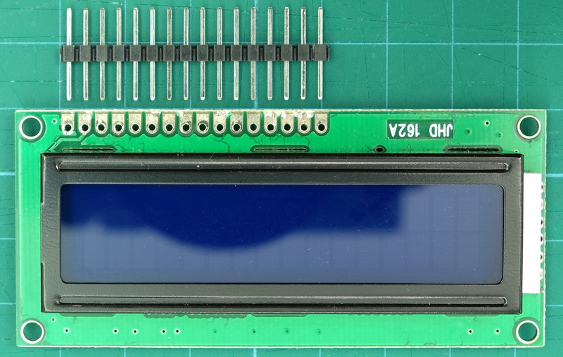
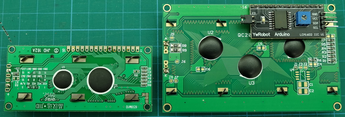
JHD162A Pins
HD44780 compatible displays like the JHD162A display have 16 pins (14 plus 2 for a backlight).
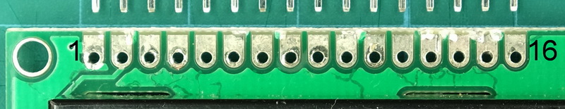
| 1 | 2 | 3 | 4 | 5 | 6 | 7 | 8 | 9 | 10 | 11 | 12 | 13 | 14 | 15 | 16 |
| VSS | VCC | VEE | RS | R/W | E | DB0 | DB1 | DB2 | DB3 | DB4 | DB5 | DB6 | DB7 | LED+ | LED- |
- VSS is GND
- VCC is voltage in.
- VEE is the display contrast pin.
- The RS pin is the Register Select pin. The HD44780 can accept 2 kinds of data; text and commands. The RS pin tells the HD44780 which type data the current value is. Set the pin LOW for command data and HIGH for ascii character data. The pin actually controls where in the LCDs memory data is written to. There are 2 options.
- 1 – The data register. This holds values intended for the screen.
- 2 – An instruction register. This is used to pass instructions to the screen. IE the current data is a command.
- The R/W pin is a Read/Write pin. Apart from writing to the screen you can also read from it and the R/W pin controls which one you are doing. Set R/W LOW for write and HIGH for read. Note: the default Arduino LCD library only allows you to write and why most getting started circuits show this pin connected directly to GND (mine included).
- E is the Enable pin, this enables writing to the registers. It tells the LCD there is data available on the data pins
- BD0 to BD7 are data pins. These are used to pass the value you wish to write to a register. Or to read when you are checking the value of a register.
- LED+ and LED- are used to power the back light LED if one is available
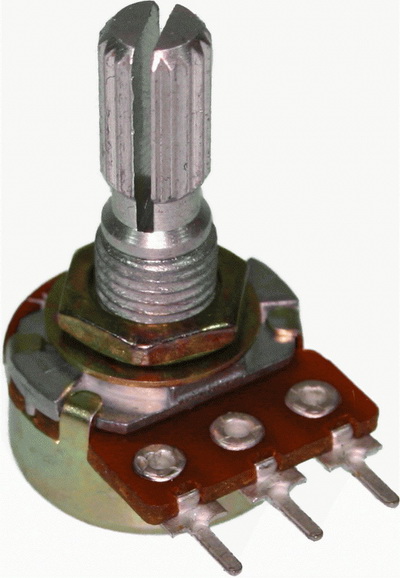
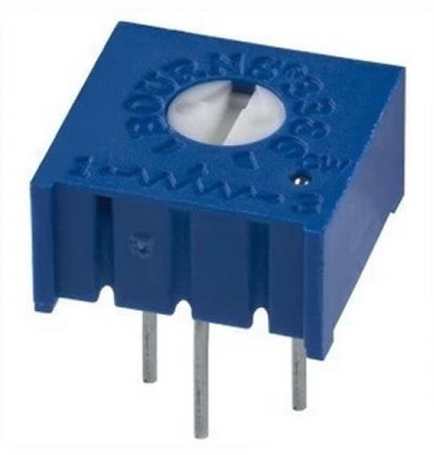
VEE controls the screens contrast and is generally connected to a potentiometer allowing the contrast to be adjusted. In these examples I am using a fairly large 10K pot but small trimmers can also be used.
4bit and 8Bit
HD44780 compatible displays can use 4bit mode or 8bit mode. In 4bit mode 4 pins are used for the data and in 8bit mode 8 pins are used. In 4bit mode the 8bits are split in to 2 4bit values and sent to the lCD separately. This takes extra time. Of course, we are talking milliseconds so you are unlikely to notice any difference.
Update: There does not appear to be any speed difference between 4bit mode and 8bit mode when using the default LiquidDisplay library. This may be due to the library not using the R/W pin correctly or it may be due to how the Arduino maps pins. Have now found further reference over at PRJC. The page also lists the LiquidDisplayFast library. So if you really need the screen to update quickly the LiquidDisplayFast library or the NewLiquidCrystal library (5 times faster) may be the way to go. There is also a difference when using the NewLiquidCrystal library which appears to use the RW flag correctly and can be up to 5 times faster than the default library.
It all comes down to pins, if you want to have an LCD but need the pins for other things go 4bit. If speed is important and you don’t need the pins, go 8bit. If pins are really important and you can’t spare even the ones required for 4bit then you should consider using a I2C adapter. This is slower still but uses far fewer pins (just 2). See below for more.
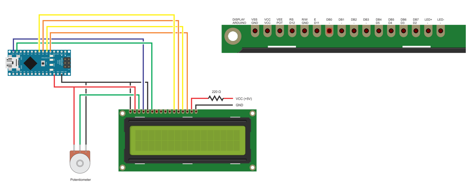
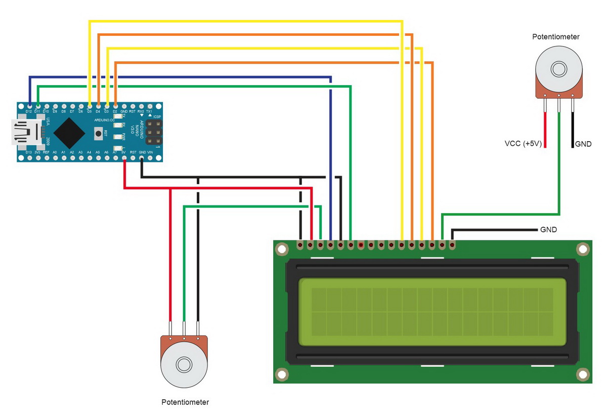
Connecting to an Arduino
| Display | VSS | VCC | VEE | RS | R/W | E | DB0 | DB1 | DB2 | DB3 | DB4 | DB5 | DB6 | DB7 | LED+ | LED- |
| Arduino | GND | VCC | POT | D12 | GND | D11 | – | – | – | – | D5 | D4 | D3 | D2 | VCC+RES | GND |
The chances are you will need to solder header pins to the display, after this create the following circuit.
Because we are using 4bit mode, the R/W pin is pulled LOW by connecting it to GND.
Sketch
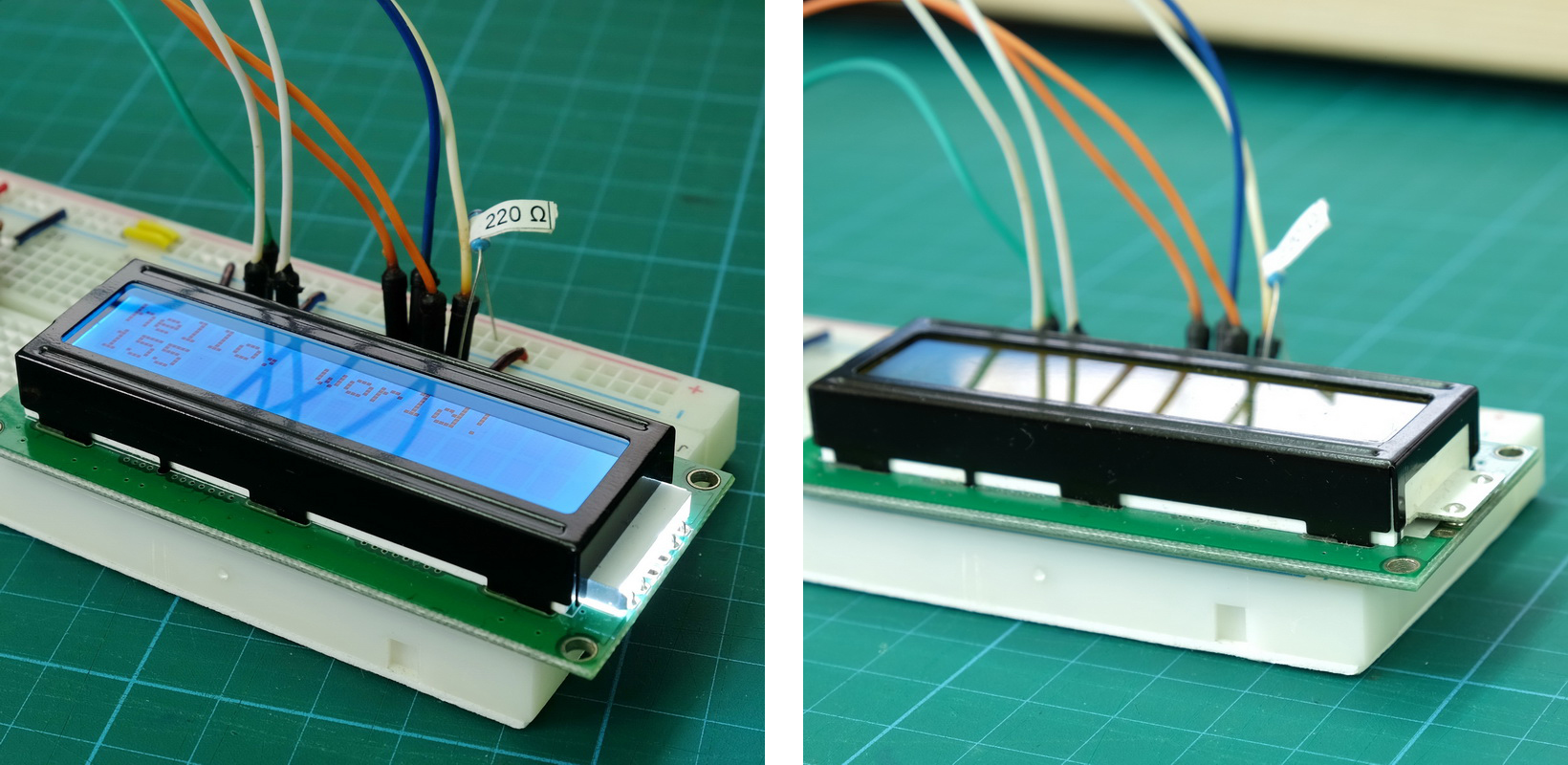
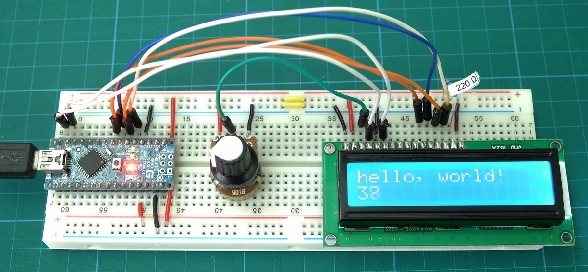
The sketch we are starting with is the Hello World example found on the Arduino website.
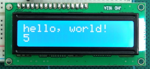
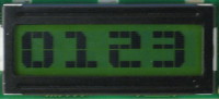
Open the IDE, copy the below sketch and paste in to the IDE and upload. If everything is OK you should see the LCD come to life and display “hello, world!” on the top line. On the bottom line you should see a count slowly count up in seconds.
If you are using an older IDE you may get a “No such file or directory” compile error:
D:\ProgsII\arduino-163\libraries\NewliquidCrystal\I2CIO.cpp:36:21: fatal error: Wire.h: No such file or directory
    #include <Wire.h>
                     ^
compilation terminated.
Error compiling.
If you do, either download the latest IDE or edit the library file.
To edit the library file, go to the NewLiquidCrystal library folder, find the I2CIO.cpp file,

open in a text editor, find the following (will be near the top of the file)
#if (ARDUINO < 10000)
   #include <../Wire/Wire.h>
#else
   #include <Wire.h>
#endif
and change it to
#include <Wire.h>
The sketch should now compile.
/* LiquidCrystal Library - Hello World Demonstrates the use a 16x2 LCD display. The LiquidCrystal library works with all LCD displays that are compatible with the Hitachi HD44780 driver. There are many of them out there, and you can usually tell them by the 16-pin interface. This sketch prints "Hello World!" to the LCD and shows the time. The circuit: * LCD RS pin to digital pin 12 * LCD Enable pin to digital pin 11 * LCD D4 pin to digital pin 5 * LCD D5 pin to digital pin 4 * LCD D6 pin to digital pin 3 * LCD D7 pin to digital pin 2 * LCD R/W pin to ground * LCD VSS pin to ground * LCD VCC pin to 5V * 10K resistor: * ends to +5V and ground * wiper to LCD VO pin (pin 3) Library originally added 18 Apr 2008 by David A. Mellis library modified 5 Jul 2009 by Limor Fried (http://www.ladyada.net) example added 9 Jul 2009 by Tom Igoe modified 22 Nov 2010 by Tom Igoe This example code is in the public domain. http://www.arduino.cc/en/Tutorial/LiquidCrystal */ // include the library code: #include <LiquidCrystal.h> // initialize the library with the numbers of the interface pins LiquidCrystal lcd(12, 11, 5, 4, 3, 2); void setup() { // set up the LCD's number of columns and rows: lcd.begin(16, 2); // Print a message to the LCD. lcd.print("hello, world!"); } void loop() { // set the cursor to column 0, line 1 // (note: line 1 is the second row, since counting begins with 0): lcd.setCursor(0, 1); // print the number of seconds since reset: lcd.print(millis() / 1000); } |

Sketch Main Parts
This is a fairly simply sketch so there are not too many key parts.
#include <LiquidCrystal.h> |
Tell the compiler you want to add the LiquidDisplay library
LiquidCrystal lcd(12, 11, 5, 4, 3, 2); |
Create a instance of the lcd object using 4bit mode by only specifying 4 data pins (5,4,3,and 2).
lcd.begin(16, 2); |
Initialize the LCD and specify the size.
lcd.print("hello, world!"); |
Display “hello, world!” at the current cursor position. Since this is the first thing printed the cursor is at the default 0,0 position.
lcd.setCursor(0, 1); |
Move the cursor to position 0,1. This is the first place on the second line (x,y).
lcd.print(millis() / 1000); |
Display the number of seconds since the Arduino started or was reset (millis() divided by 1000 equals seconds). numeric values are automatically converted to ascii before displaying. This means the number 1 is played as “1”.
Parallel interface back light
When using a LCD with a parallel interface you have full control over the back light. This not only includes turning it on and off but also dimming it. Turning on and off is simply a case of connecting to power or not. To make back light appear dimmer we can use another potentiometer or PWM.
A potentiometer offers manual control. PWM offers automated control.
The back light of the JHD162A is a LED matrix, this means we can make them dimmer by increasing the resistance, either by using different resistor values or by using a potentiometer.
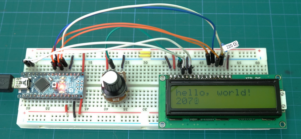
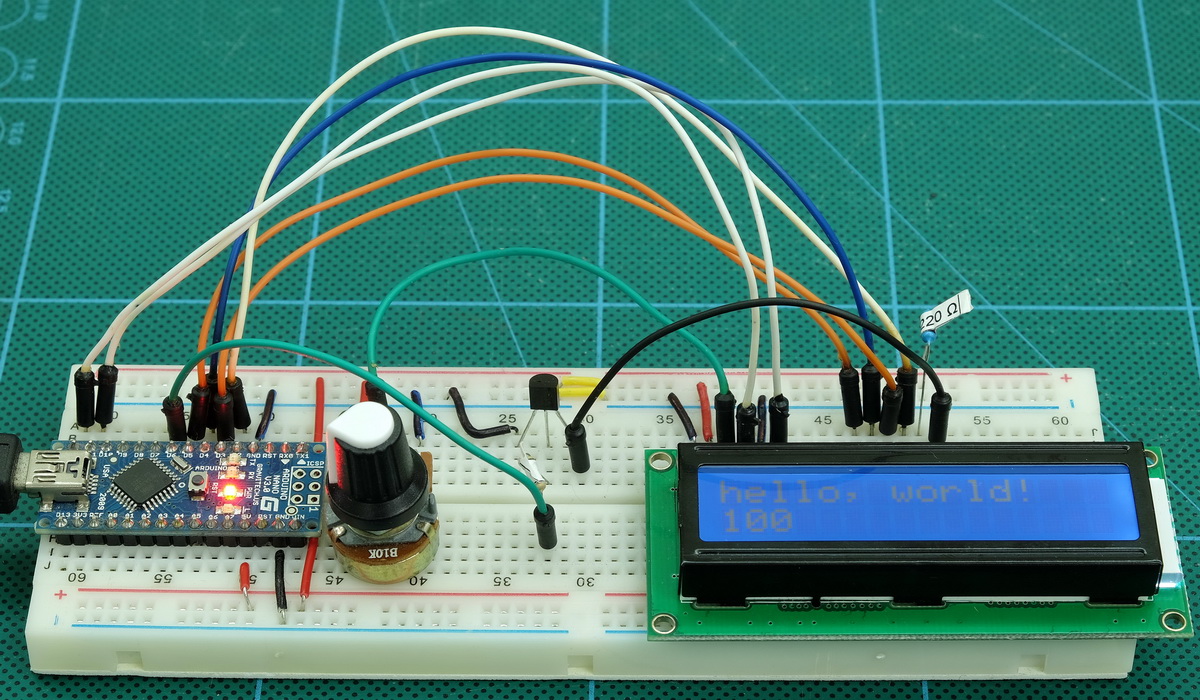
Here is the bread board example with an added potentiometer connected to LCD pin 15. This is the back light power + pin.
![]()
Turning the potentiometer increases or decreases the back light brightness.
To allow the Arduino to control the back light we use a PWM signal. The PWN signal turns the LED back light on and off very quickly which, to the human eye, makes it look dimmer.
It is tempting to connect the back light power connector directly to an Arduino pin and this may work. But we don’t know how much current the back light draws and the data sheet does not always say. So you shouldn’t do it. Although Arduino pins can supply a maximum of 40mA, 40mA is the maximum for very short periods of time. Arduino pins cannot provide the full 40mA for any length of time. A better way is to use a transistor as a switch. In this example I am using a 2N222 NPN transistor on the LOW side (GND side). You could also use a PNP transistor on the HIGH side (+5V side).
Connect the back light plus pin to 5V via a 220 ohm resistor (or similar).
Connect the back light minus pin to the collector (C) pin of the 2N222.
Connect transistors emitter pin (E) to GND.
Connect the transistors base pin (B) to a 1K ohm resistor and then the resistor to Arduino pin 6. I chose pin 6 because it can be used for PWM.
I modified the Hello World sketch to add PWM control. The following sketch increases the PWM value by 10 every loop. This increases the back light brightness (0 is off, 255 is full on). You may notice that the value of brightness never gets to 255!
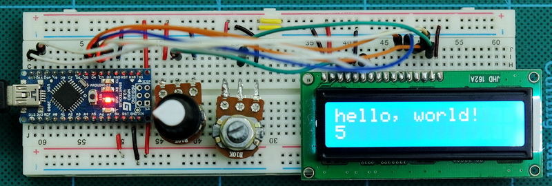
After you have added the 2N2222 transistor to the circuit upload the sketch.
// include the library code: #include <LiquidCrystal.h> // initialize the library with the numbers of the interface pins LiquidCrystal lcd(12, 11, 5, 4, 3, 2); int backLightPWMpin = 6; int brightness = 0; void setup() { // set the back light pin to output pinMode(backLightPWMpin, OUTPUT); // set up the LCD's number of columns and rows: lcd.begin(16, 2); // Print a message to the LCD. lcd.print("hello, world!"); } void loop() { // increase the brightness brightness = brightness + 10; // the maximum value for analogeWrite is 255 if (brightness >255) { brightness = 0; } // set the PWM speed to the brightness value analogWrite(backLightPWMpin, brightness); // display the brightness value on screen. The spaces clear the old value. Required when we go from 250 to 0. lcd.setCursor(0, 1); lcd.print( " " ); lcd.setCursor(0, 1); lcd.print( brightness ); delay(1000); } |
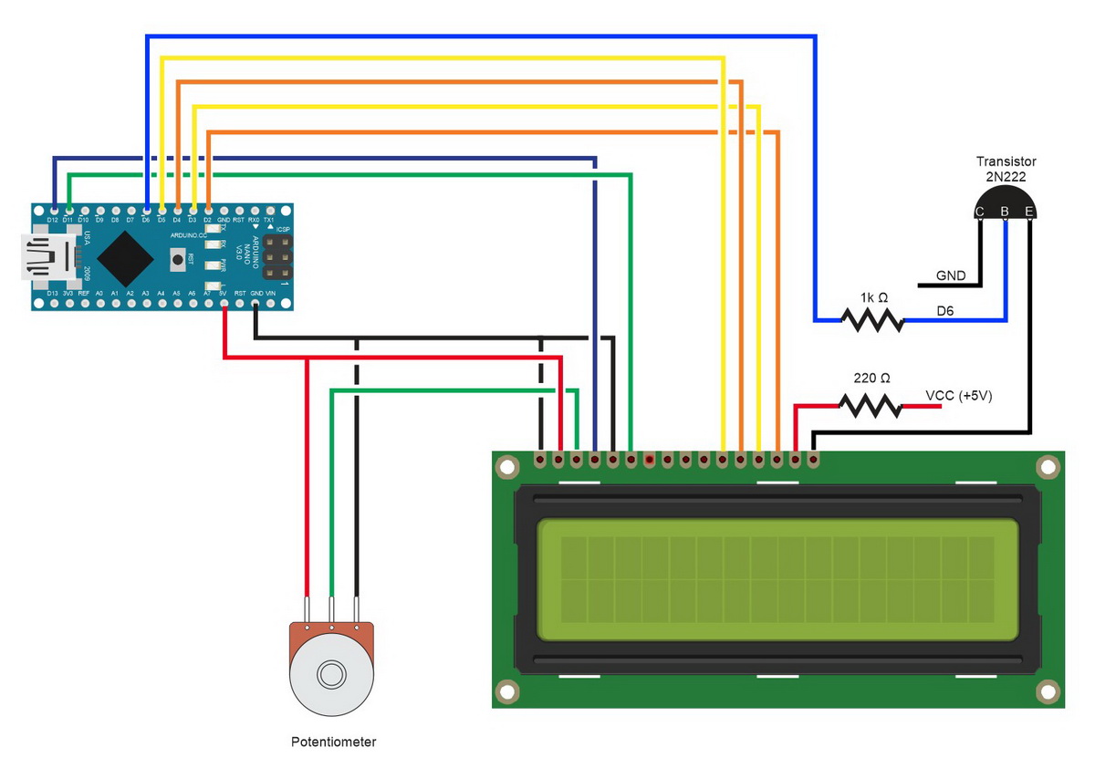
Here we are using D6 to control the back light brightness and changing the value of brightness in analogWrite(backLightPWMpin, brightness) changes the back light intensity.
![]()
Automatic dimmer control using PWM.
If you have read through the commands in the above table you may have noticed that the NewLiquidCrystal library has this function built in. The setBacklight() command does exactly the same thing in the same way.
First let the library know what pin you are using with setBacklightPin() then set the brightness using setBacklight(). As with analogeWrite 0=off and 255 = full on.
I2C Interface: Getting Started with a 20×4 display with I2C daughter board
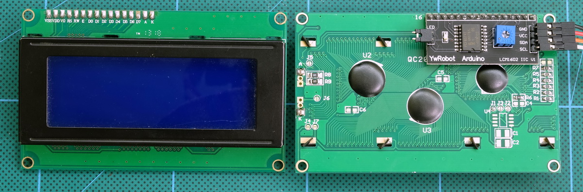
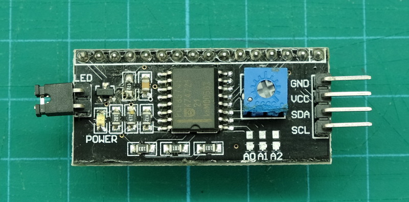
The I2C daughter board is a small add on that converts I2C communication to parallel communication. Among the various different I2C adapters there are two common ones. One with a fixed address and one with jumpers/solder pads that allow you to change the address.
The small trimmer/pot is connected to VEE on the LCD and is used to adjust the contrast.
Modules with fixed addresses usually have an address of HEX 27 (0x27) but can also have 0x20 or 0x3F (one of the first adapters I bought was set to 0x3F but I haven’t come across any since).
Modules with jumpers/pads normally have 3 jumpers, A0, A1 and A2.
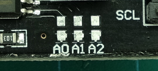
If none of the jumper are closed the address is 0x27 (normal status when purchased).
| A0 | A1 | A2 | Address | |
| OPEN | OPEN | OPEN | 0x27 | |
| CLOSED | OPEN | OPEN | 0x26 | |
| OPEN | CLOSED | OPEN | 0x25 | |
| CLOSED | CLOSED | OPEN | 0x24 | |
| OPEN | OPEN | CLOSED | 0x23 | |
| CLOSED | OPEN | CLOSED | 0x22 | |
| OPEN | CLOSED | CLOSED | 0x21 | |
| CLOSED | CLOSED | CLOSED | 0x20 |
If you cannot get the screen to work and you think you have the wrong address use an I2C scanner to find the screen’s address or use the diagnostic tool within the Extensible hd44780 LCD library (see below).
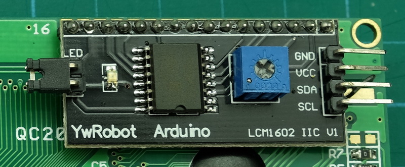
The adapters have 6 pins. 2 for power, 2 for communication, and 2 for the back light.
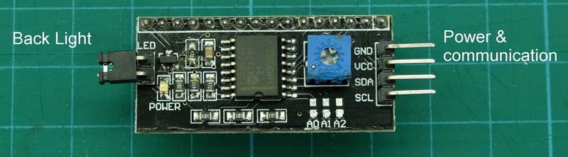
Power and communication pins
GND goes to GND
VCC goes to +5V
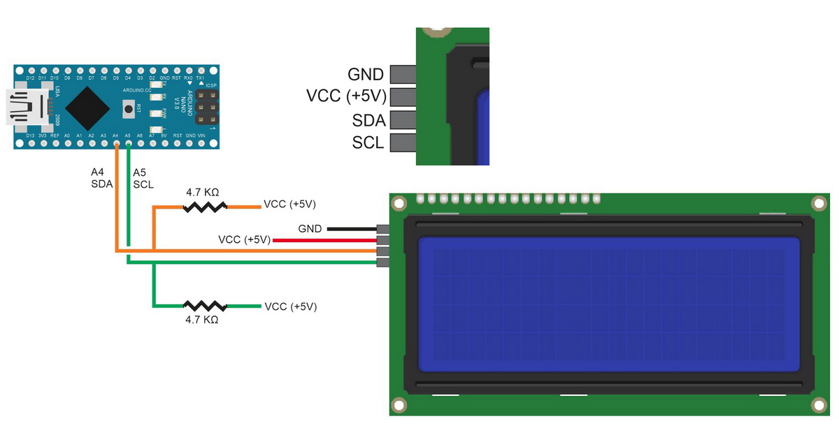
SDA goes to Arduino pin A4
SCL goes to Arduino pin A5
I2C works best with pull up resistors, therefore A4 and A5 should be pulled HIGH to 5V with 4.7k ohm resistors.
Back light pins
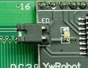
On the I2C adaptor, the back light is controlled by two pins. Short the pins with a jumper to enable the back light. Remove the jumper to disable the back light. On some adapters the positive pin connects directly to the controller chip and on others it goes to a transistor.
On LCDs with the I2C adapter, the back light cannot be dimmed. It can be on or off only. To enable the Arduino to control the back light, connect the back pins on the I2C board to a transistor and then the transistors base pin to the Arduino (via a 1K ohm resistor).
All the I2C boards I have use the PCF8754 chip, either the Philips PCF8754T or the NXP PCF8574/PCF8574A. The devices without an ‘A’ in the suffix have a base address of 0x20 and a range from 0x20 to 0x27. The devices with an ‘A’ in the suffix have a base address of 0x38 and a range from 0x38 to 0x3F.
Philips PCF8754T data sheet.
NXP PCF8574/PCF8574A data sheet.
Once you have everything connected, LCDs with a I2C adaptor act pretty much like those without. Using the library is the same and the commands are the same.
Circuit diagram
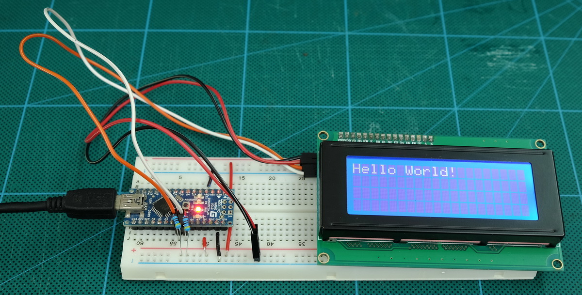
Hello World
Here is a very quick hello world sketch. It simply displays “Hello World!” on the screen.
#include <Wire.h> #include <LiquidCrystal_I2C.h> // ADDR, EN,RW,RS,D4,D5,D6,D7,BL,POLARITY LiquidCrystal_I2C lcd(0x27, 2, 1, 0, 4, 5, 6, 7, 3, POSITIVE); void setup() { lcd.begin(20, 4); lcd.setCursor(0, 0); lcd.print("Hello World!"); } void loop() { ; } |
If you look at the library wiki you may notice that the example they give shows the constructor with just the address, no pin data.
LiquidCrystal_I2C lcd(0x38); // Set the LCD I2C address |
When the pin data is not given, the library will add the default pin mapping for the LCDXIO LCD/expander backpack sold by Francisco Malpartida’s ElectroFun company and unfortunately this is not the same as other I2C adapters and so we need to specify the pins.
If your LCD shows faint solid blocks with one of the blocks flashing (and usually no back light) it means you have the wrong pin definitions.
Back light Control
When using an I2C adaptor, we can turn the back light on and off with the lcd.backlight() and lcd.noBacklight() commands. No extra connections are required.
The following sketch displays Hello World on the LCD and then flashes the back light on and off every second. This uses the same circuit as above. Just SDA and SCL on pins A4 and A5.
Dimming the back light is not possible when using a I2C adapter unless you modify the hardware.
// Simple 20x4 LCD with I2C adapter test // // Displays Hello World on the LCD and then flashes the back light on and off #include <Wire.h> #include <LiquidCrystal_I2C.h> // ADDR, EN,RW,RS,D4,D5,D6,D7,BL,POLARITY LiquidCrystal_I2C lcd(0x27, 2, 1, 0, 4, 5, 6, 7, 3, POSITIVE); void setup() { lcd.begin(20, 4); lcd.setCursor(0, 0); lcd.print("Hello World!"); delay(2000); } void loop() { lcd.noBacklight(); delay(1000); lcd.backlight(); delay(1000); } |
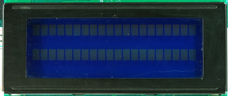
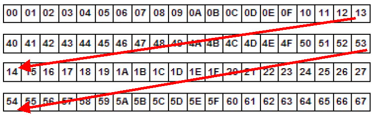
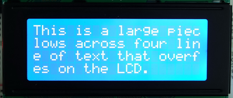
20×4 LCD memory map and line overflow
Due to how the memory is allocated inside the LCD device, characters may not over flow as you expect. When characters over flow from line 1 they continue on line 3. When line 2 over flows the text continues on line 4.
// Demonstration of overflow on a 20x4 LCD #include <Wire.h> #include <LiquidCrystal_I2C.h> // ADDR, EN,RW,RS,D4,D5,D6,D7,BL,POLARITY LiquidCrystal_I2C lcd(0x27, 2, 1, 0, 4, 5, 6, 7, 3, POSITIVE); void setup() { lcd.begin(20, 4); lcd.setCursor(0, 0); lcd.print("This is a large piece of text that overflows across four lines on the LCD."); } void loop() { ; } |
Custom Characters
Most HD44780 compatible LCDs have 8 memory locations that can be used for creating user defined characters. You create a custom character by putting the character data in to a byte array then passing the array to the library using createChar() command. Each character occupies a 5×8 grid
If you use binary when defining the array you can see the character you are creating. For example, a smily face :) and a sad face :(
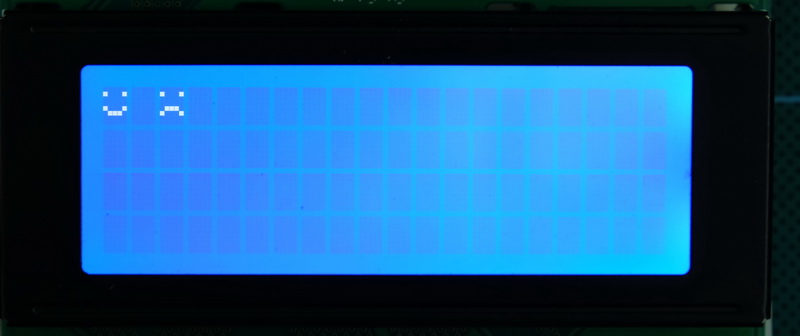
// Custom characters #include <Wire.h> #include <LiquidCrystal_I2C.h> // ADDR, EN,RW,RS,D4,D5,D6,D7,BL,POLARITY LiquidCrystal_I2C lcd(0x27, 2, 1, 0, 4, 5, 6, 7, 3, POSITIVE); void setup() { lcd.begin(20, 4); byte chr1[8] = { B00000, B10001, B00000, B00000, B10001, B01110, B00000, B00000 }; byte chr2[8] = { B00000, B10001, B00000, B00000, B01110, B10001, B00000, B00000 }; lcd.createChar(1, chr1); lcd.createChar(2, chr2); lcd.setCursor(0, 0); lcd.write(1); lcd.setCursor(2, 0); lcd.write(2); } void loop() { ; } |
lcd.createChar(1, chr1); creates character 1 using the data in the array named chr1.
To display this character simply use lcd.write(1);
Although only 8 characters can be created at any one time, the characters can be redefined at anytime and creating new characters on the fly can give the appearance that more than 8 exist, although only 8 can be displayed at any one time.
If you redefine a character while it is being displayed on screen then the character will change to the newly created character.
Online Custom Character Generator
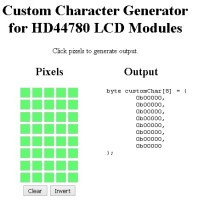 Omer Kilic has created a nice custom character generator that automatically produces the Arduino code.
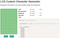 maxpromer has another, similar, generator here.
Large Fonts
 Using custom characters it is possible to create large fonts. These were created by digimike on the Arduino forum
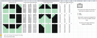 Over at AVR Freaks, china92 posted an Excel based design guide.
There are many many more and googling “Arduino LCD large font” will give you a lot of places to look.
Custom Character Demos
Arduino demo: www.youtube.com/watch?v=ZarVHGqWNkk
Non Arduino : www.youtube.com/watch?v=4wjj0Xcu2F8
Extensible hd44780 LCD library
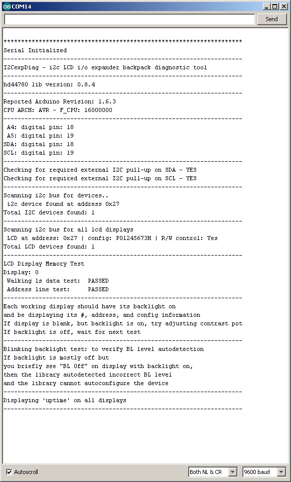
Bill Perry’s Extensible hd44780 LCD library looks very promising. Extensible hd44780 LCD library can be downloaded from github. The library covers all the regular commands and includes a diagnostic sketch in the examples. Have an HD44780 LCD but can’t get it working or not sure how to initialise the library, run the diag sketch and it will tell you.
Install the library in the usual way. Load the “I2CexpDiag” sketch from the library examples
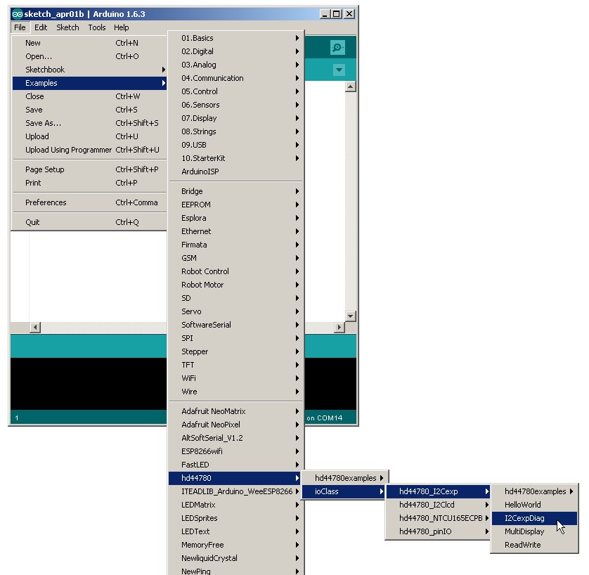
Compile, run and open the serial monitor.
Notes
Resetting the Arduino does not reset the LCD
Using clear() is very slow. In many cases filling the screen with spaces is quicker. If speed is important, only update the parts of the screen that need updating and don’t write data if it has not changed.
Using home() is also slow.
There is an issue with the back light on some LCD shields. See this post in the Arduino forum. The Extensible hd44780 library works around the problem in software.
Further information & links
Francisco Malpartida’s New LiquidCrystal wiki and download.
Good information about LCDs with I2C adapters at Arduino Info. The I2C LCD page also has information about other types of adapters. It is worth while checking out the whole site. Lots of good information about Arduino and Arduino compatible modules.
Reducing Arduino Pins: If you don’t have a I2C adaptor but have a 74HC595 and want to use less pins have a look at Juan Hernandez’s library that uses SPI and a 74HC595.
A new HD44780 LCD library by Bill Perry looks very promising. Extensible hd44780 LCD library can be downloaded from github. The library covers all the regular commands and includes a dianostic sketch in the examples. Have a HD44780 LCD but not sure how to initialise the library, run the diag sketch and it will tell you.
Programming Electronics Academy has a good beginner guide to LCD character displays that covers character positions.
Arduino forum post about back light brightness.
 Want to really get to understand how these screens work? The 8-Bit Guy has an excellent video showing how to build a non microprocessor control box for an HD44780 LCD. I remember programming 6800 based boards like this many many years ago.
Very nice page and writeup.
A couple of things worth noting.
With fm’s library setBackLightPin() is obsolete. It was left in for backward compatibility but the intent is that the pin and polarity are now set in the constructor. My reasoning for doing this (yes I did lots of work on that library) was to ensure that the only differences between i/o interfaces is handled in the constructors and the main line sketch code would work across all h/w without modifications.
One of the big advantages of hd44780 is that it can be installed from the IDE library manager.
Another advantage for the LCDs that use i2c backpacks is that auto configuration.
So unlike with fm’s library the sketch does not have to specify the i2c address, pin mappings, or backlight control information.
The backpack class also supports backpacks that use MCP23008 chips like the adafruit #292 board.
In terms of 8 bit vs 4 bit speed. Yes 8 bit is faster. In terms of using the r/w line, in reality it will typically be slower since it requires flipping all the i/o pins around from output to input mode and then back again. If not using direct port i/o that will definitely make things slower, particularly on the AVR platforms since the AVR core library functions like digitalWrite()/digitalRead() use poor semantics and are using very simplistic code that is quite slow.
hd44780 does very smart command execution processing. It allows the Arduino to run in parallel with the LCD commands. i.e there are no blind/dumb fixed period delays. hd44780 only delays if the processor attempts to talk to the LCD before the command execution for the previous has not passed. And even then it will only delay the remaining portion of time vs the entire amount of time like other libraries. This allows it to hide the overhead of many things like the i2c byte transfer times, and the the overhead of operations like digitalWrite().
It also allows the sketch to configure command execution times for LCDs that might be slower than the default reference design or for displays that are faster for those that want a bit more performance.
hd44780 has been tested on many different platforms, pic32, ARM, AVR, ESP8266 and the intent is that it “just works’ on all platforms.
I’ve got a bunch of stuff planned for hd44780, including handling line endings and display scrolling.
But as of right now since it isn’t, hd44780 will crash the compiler with an error if println() is every used in a sketch for the lcd object.
Excellent tutorial. Got me going in a few minutes. I really appreciate the detailed information on the library commands as well.
Great job!
Thanks so much for the comprehensive tutorial. I’d like to note that it is certainly possible to dim the backlight on LCDs that come with an I2C adaptor. It’s as simple as wiring the upper pin (the one labeled LED) of the I2C board to a PWM pin in the Arduino. Using analogWrite() will vary the LED brightness from 0 (LED off) to 255.
Here’s a simple sketch to demonstrate this:
#include
#define BRIGHTNESS_PIN 6 // Must be a PWM pin
LiquidCrystal_I2C lcd(0x27, 2, 1, 0, 4, 5, 6, 7, 3, POSITIVE);
byte brightness = 0;
bool sense = 1;
void setup()
{
lcd.begin(16, 2);
lcd.setCursor(0, 0);
lcd.print(“Here’s some text”);
}
void loop()
{
analogWrite(BRIGHTNESS_PIN, brightness);
delay(10);
if(sense) {
if(brightness 0) {
brightness–;
} else {
sense = 1;
}
}
}
Is it possible , for i2c equipped display, to be connected to pins other than A4 and A5 on the Arduino?
yes but you need to use a software i2c library such as SoftI2CMaster. Have a look at https://github.com/felias-fogg/SoftI2CMaster
Many thanks, your tutorial is great, it’s been very helpful to my understanding of this device.
Great tutorial.
Just one question: it’s okay to do the exact same same thing to control contrast by code, isn’t it? Same resistors, same transistor ?