A comprehensive look at the HM-10 BLE 4.0 modules.
Using.
Connecting.
Updating.
This page is out-of-date and no longer being updated. For the newer guides jump to the quick links page
Introduction
The HM-10 is a small 3.3v SMD Bluetooth 4.0 BLE module based on the TI CC2540 or CC2541 Bluetooth SOC (System On Chip). The HM-10 is made by Jinan Huamao Technology and is one of many Bluetooth devices they produce.
There are 4 versions of the HM-10. The differences are usb pads and a crystal.
1 – with usb pads and the additional crystal
2 – with usb pads without the extra crystal
3 – no usb pads but with the additional crystal
4 – no usb pads, no extra crystal.
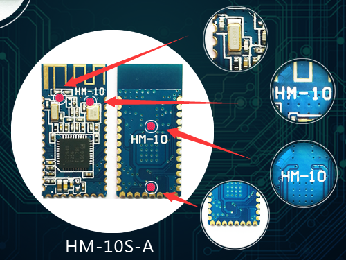
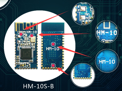
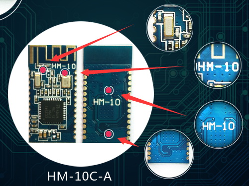
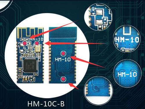
The HM-10C-A and HM-10C-B models do not have the pads along the bottom (the USB connections) and therefore, have 26 pads instead of 34 which makes it a little cheaper to produce. The B variant boards lack the external crystal, again making them a little bit cheaper. Operationally they are all the same.
HM-10 Basic specs
- Based on the CC2540 or the CC2541 chip
- +2.5v to +3.3v
- Requires up to 50mA
- Uses around 9mA when in an active state
- Use 50-200uA when asleep
- RF power: -23dbm, -6dbm, 0dbm, 6dbm
- Bluetooth version 4.0 BLE
- Default baud rate firmware before V700 is 9600
- Default baud rate firmware V700 and up is 115200
- Default PIN is 000000
- Default name is HMSoft
The latest HM-10s all appear to the the CC2541 chip. This is the same as the CC2540 except it is lower power and has a shorter range. The CC254x is based on the 8051 and runs at 32MHz.
The HM-10 is has become a very popular Bluetooth 4 BLE module for use with the Arduino. In part due to the standard UART serial connection that makes it fairly straight forward to connect to an Arduino. The UART layer is a good thing and a bad thing, it allows ease of use but it hides the BLE layer so you have no control over the actual BLE side of things. The HM-10 is Bluetooth version 4.0 only. This means it cannot connect to Bluetooth 2/2.1 modules such as the HC-06 and HC-05.
The HM-10 is controlled via AT commands which are sent over the serial UART connection. There are a host of commands, some simple, some more complex, and these are covered later.
HM-10 on a breakout board
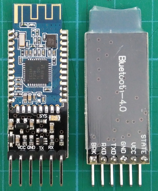
The HM-10 is available as a small SMD module and also available mounted to a breakout board that exposes the power and UART connections to breadboard friendly male pins. The breakout board includes a 3.3v power regulator that makes them 5V compatible. This makes them ideal for hobbyists like me. You should note that the RX pin is is still 3.3v and when using a 5v Arduino you should covert the Arduino’s 5v TX to 3.3v for the HM-10 RX.
| Pin | Description |
| STATE | Connection status LOW when not connected. HIGH when connected |
| VCC | Power in. 3.6v to 6v |
| GND | Common ground |
| TXD | Serial UART transmit |
| RXD | Serial UART receive |
| BRK | Break pin. When there is an active connection, bringing the BRK pin LOW breaks the connection |
On board LED
The on board LED blinks when waiting for connection. It blinks half a second on, half a second off.
The LED becomes solid on when a connection is made and returns to blinking when the connection is broken.
The LED changes to solid on when pairing. After pairing it returns to flashing. It basically makes a connection to pair and so turns on the LED to show the connection status. After pairing is completed the connection is closed and the LED is turned off.
The behavior of the LED can be changed using the PIO1 command.
“AT+PIO10” – Default setting. When not connected the LED blinks 500ms on, 500ms off. When connected the LED is solid on.
“AT+PIO11” – When not connected the LED is off. When connected the LED is solid on.
STATE Pin
The STATE pin is LOW when there is no connection and goes HIGH when a connections is established.
BRK Pin
The BRK pin allows you to cancel a connection. When there is an active connection, bringing the BRK pin momentarily LOW breaks the connection. When there is no connection making the BRK HIGH or LOW has no effect. Although not strictly required, pulling the BRK pin HIGH for normal use will stop the pin floating.
Fakes
There are lots of comments on the internet about fake HM-10s and even Jinan Huamao includes information in the data sheets. I do not see the non-HM-10s as fakes, I see them as similar devices with different firmware. To me if they were fakes they would copy the firmware.
I think a lot of the problem comes from how the non-HM-10s are sold, especially on places like ebay and aliexpress. You will often see modules sold as HM-10s when they are in fact not. One of the easiest ways to spot the non-HM-10s was the lack of a crystal, unfortunately you can now buy actual HM-10s without the crystal so the confusion is likely to get worse.
Jinan Huamao Technology Website
Website: http://www.jnhuamao.cn/index.asp
Main products page: http://www.jnhuamao.cn/bluetooth.asp
Firmware downloads: http://www.jnhuamao.cn/download_rom_en.asp?id=1#
Firmware release notes: http://www.jnhuamao.cn/index_en.asp?ID=1
Bluetooth 4 information pack
As well as firmware files, there are quite a few resources available on the Huamao website:
The information pack is available by clicking on one the HM-10 images on the Huamao website Bluetooth page. Jump to the website, click on one of the HM-10 images and download the zip archive.
You can also download from here.
The zip file contains the data sheet, instructions for the self leaning mode, and other useful notes. The datasheet in the dlownload is V610/V707 2020-02.
The data sheet in the download shows V610/V707 and is not fully up-to-date; it does not include the new AT+READOF command and has the old AT+CO command. It does include AT+PACK which was introduced in v702 though. Huamao version control looks to be as good as mine…..
The readme in the archive is not up-to-date either (goes up to V605). The readme that comes with the firmware download is better and includes V709 which is the latest. The link for the firmware shows V710 though :-(
Firmware
The latest firmware is v709 (even though it say V710) and can be downloaded from the firmware download page.
If you are updating from a V700 or later, remember the baud rate changed to 115200.
Here are the updates/changes since V700
V709
-Add AT+Z1 AT+Z2 AT+Z3 AT+Z4 AT+Z5 AT+Z6 command.
Those commands is used to change full advertisiment package and ScanResponse package
Please use HM_Config_Assistant.exe to get AT commands list.
V708
-Add deep sleep mode
AT+IMME1 and AT+SLEEP (or AT+PWRM0), let module into 0.1uA deep sleep mode.
V707
-Modify AT+ADDR command
AT+ADDR command used to change module MAC.
Query command AT+ADDR?
Setup command AT+ADDR
P1: 12 Bytes, MAC string.
V706
-Add AT+UART command
AT+UART command used to switch UART wake function when module in sleep mode.
P1: 1 Byte, possible value ?, 0, 1
?: Query
0: Open UART wake function (default value)
1: Close UART wake function.
V705
-Add AT+READOF command
AT+READOF?, used to read long char value
P1: 2 Bytes, Start Index.
P2: 4 Bytes, Char Handle.
V704
-Modify AT+CO command
AT+CO[P3][P4][P5], used to make connection.
P1: 1 Byte, Devie type.
P2: 12 Bytes, Device MAC
P3: 4 Bytes, Notify Handle
P4: 4 Bytes, Write Handle
P5: 2 Bytes, Write property.
P1 and P2 must be input;
V703
-Add AT+INDICA_ON command
V702
-Made wakeup function better
-Add AT+PACK command used to modify data in Advertisement package.
AT+PACK[P1][P2][P3][P4][P5][P6]
P1, P2, P3, P4, P5, P6 length all is 2.
P1, P2, P3, P4, P5, P6 value 00~FF
V701
-Add AT+SET_WAY command
V700
-Default baud rate change to 115200
-Removed AT+ANCS command
-Removed AT+COMP command
-Removed AT+128B command
-Added new function used to support different brand BLE device
-Added AT+FINDSERVICES? command
-Added AT+FINDALLCHARS? command
-Added AT+NOTIFY_ON command
-Added AT+NTOIFYOFF command
-Added AT+READCHAR command
-Added AT+CHAR command
-Added AT+READDATA command
-Added AT+READDESC command
-Added AT+SEND_DATA command
I always had issues using the HM-10 with other modules. I never got them to fully work with modules like the BT05 and the AT09. The BT05 & AT09 could receive data from the HM-10 but not the other way round.
I emailed Huamao a few times about this and didn’t get any replies but it looks like they at least addressed the problem and since firmware V700 there has been better compatibility with other BLE modules.
Other changes include
– the default baud rate changed to 115200
– At Mode now accepts commands with and without line endings.
There were many reports of Android 8.1 not connecting to cheap BLE modules (inluding fake HM-10s), Jinan Huamao support say that the HM-10 (original ones, not copies) are compatible with Android 8. I do not have Android 8 so have not tried and cannot confirm. For a while there was a message on their website stating HM-10s were compatibly with Android 8 but it appears the News section no longer exists.
Firmware version 5.49 is available in two versions; regular and long name. The regular firmware does not have an updated read me so I don’t know what changes, if any, have been made. The long name firmware adds, you guessed it, long names. Device names can now be up to 29 characters. At the same time the iBeacon function and the ANCS function have been removed. This looks to be a one off (later firmware do not have a long name version and unless you desperately need long names I suggest you stay with the regular firmwares.
Bluetooth 4 BLE
BLE is not an upgrade to Bluetooth Classic, it is a different system with different intended uses. BLE works in a very different way to the earlier Bluetooth.
BLE is designed for low energy applications and achieves this by using infrequent small packets of data. It is not really designed for continuous connections and large amounts of data. For this, Bluetooth Classic is a better choice. In essence, BLE achieves its low power consumption by not being connected very often, unlike Bluetooth Classic which maintains a constant connection.
While you can create a classic style connection using 2 HM-10s, and I give an example below, they were not designed for this and if this is all you need then you would be better suited with Bluetooth Classic modules like the HC-05s or a HC-05 and a HC-06.
There are 2 ways BLE devices can talk to each other; Broadcaster + Observer, and, Central + Peripheral. The HM-10 can use both methods.
- With Broadcaster + Observer there isn’t a standard connection, the Broadcaster, usually some kind of sensor, sends out periodic signals (advertising packets) which the Observer listens for. The Broadcaster does not normally know if anything is listening or not.
- The Central + Peripheral scenario is more like (but not exactly the same) as the classic connection. When the Central (master) device finds a Peripheral (slave) device it wants to connect to it initiates a connection and takes on the master role managing the connection and timings.
HM-10 Services and Characteristics
BLE is all about services and characteristics and like all BLE devices, the HM-10 has a set of services and each service has a set of related characteristics. Characteristics are where the values are, some are READ, some are WRITE, and some are READ and WRITE.
All the services on the HM-10 are predefined except one. This is a custom service that has one custom characteristic. Predefined services and characteristics are ones where the UUID and the name are set by the Bluetooth governing body. For example, the characteristic 0x2A00 is the device name and when a device has this characteristic it should always be the device name.
A full list of the predefined services can be found here and a list of the characteristics is here.
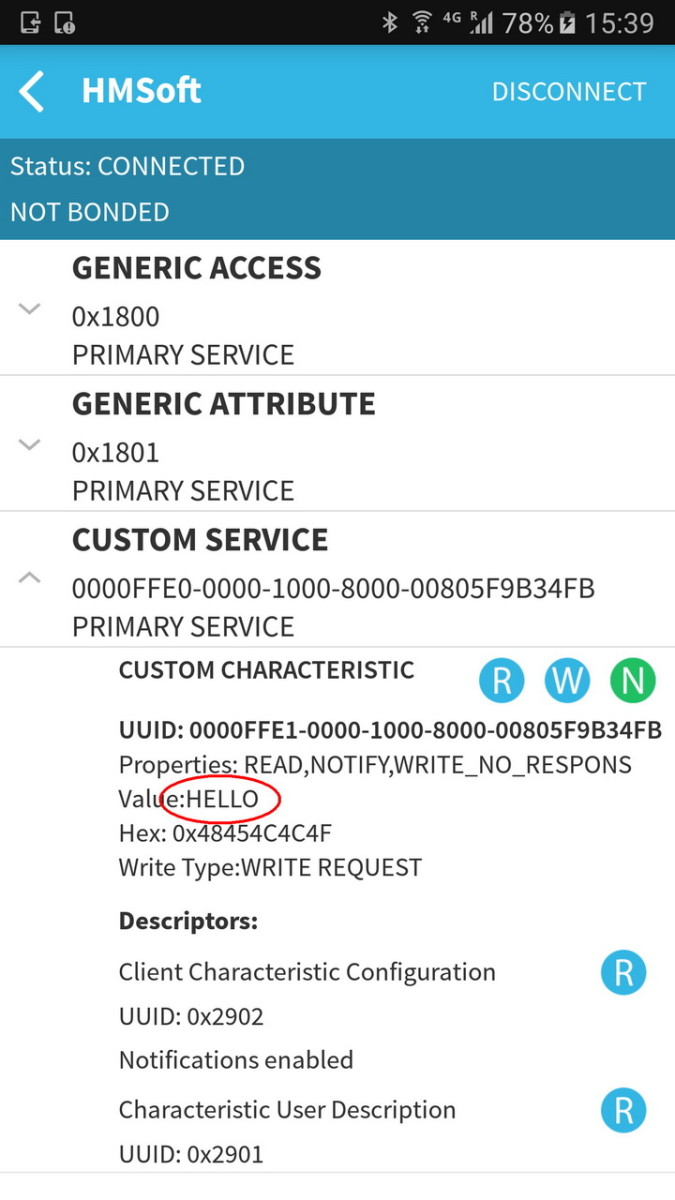
The HM-10 uses the custom characteristic to send and receive the data it receives over the serial UART interface. It works by setting the value of the custom characteristic to the value of the data to be transmitted. It then sends out a notification to the remote device to say there is new data available.
When you tell the the HM-10 to transmit “HELLO”, it first sets the value of the custom characteristic to “HELLO” and then it sends out a notification telling the remote device “Hey, I have new data, come and get it.” The remote device is scanning for the notifications and when it receives one it knows there is a new value, so it reads the data and then sends back a message saying “Thanks, I have it”.
The custom characteristic can hold up to 20 characters, this means to send a string longer than 20 characters the HM-10 splits the data in to 20 character segments and sends each one in turn until none are left.
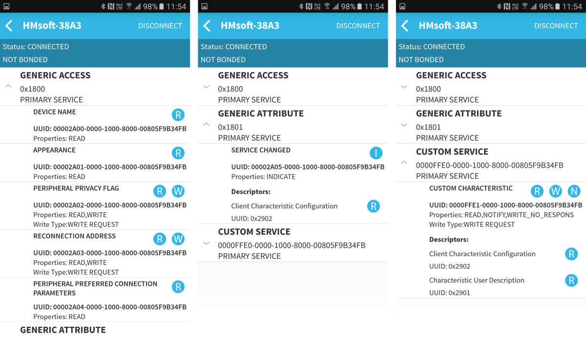
SERVICE 1
UUID: 00001800-0000-1000-8000-00805F9B34FB
GENERIC ACCESS
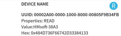
- UUID: 00002A00-0000-1000-8000-00805F9B34FB
- DEVICE NAME
- READ
- UUID: 00002A01-0000-1000-8000-00805F9B34FB
- APPEARANCE
- READ
- UUID: 00002A02-0000-1000-8000-00805F9B34FB
- PERIPHERAL PRIVACY FLAG
- READ/WRITE
- UUID: 00002A03-0000-1000-8000-00805F9B34FB
- RECONNECTION ADDRESS
- READ/WRITE
- UUID: 00002A04-0000-1000-8000-00805F9B34FB
- PERIPHERAL PREFERRED CONNECTION PARAMETERS
- READ
SERVICE 2
UUID: 00001801-0000-1000-8000-00805F9B34FB
GENERIC ATTRIBUTE
- UUID: 00002A05-0000-1000-8000-00805F9B34FB
- SERVICE CHANGED
- INDICATE
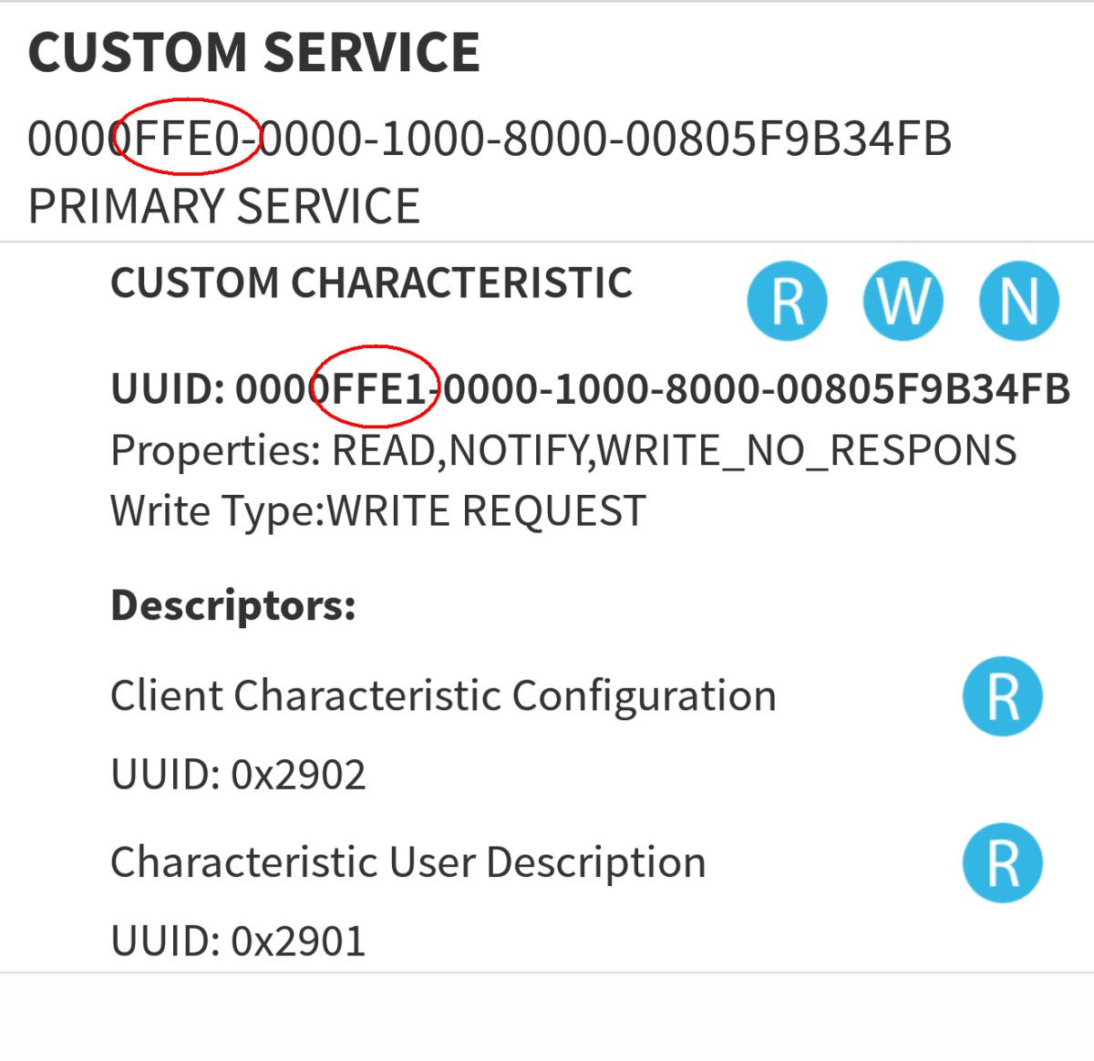
SERVICE 3
UUID: 0000FFE0-0000-1000-8000-00805F9B34FB
CUSTOM SERVICE
- UUID: 0000FFE1-0000-1000-8000-00805F9B34FB
- CUSTOM CHARACTERISTIC
- READ/WRITE/NOTIFY
The main part of the custom service UUID (FFE0) the main part of the custom characteristic UUID (FFE1) can be changed via AT commands. A second characteristic can also be added.
Get Started With the HM-10
First, lets use an Android device to read the services and characteristics from the HM-10.
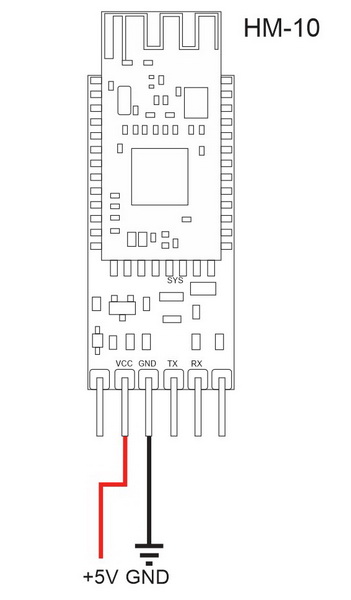
Power on the HM-10, you can use an Arduino for this but all you need is to connect 5V to HM-10 VCC and GND to HM-10 GND.
If done correctly, the LED on the HM-10 should be flashing. When a connection is established the LED will be become solid on.
Checking the HM-10 with an Android Device
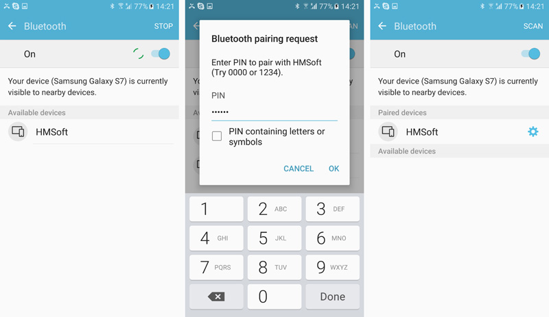
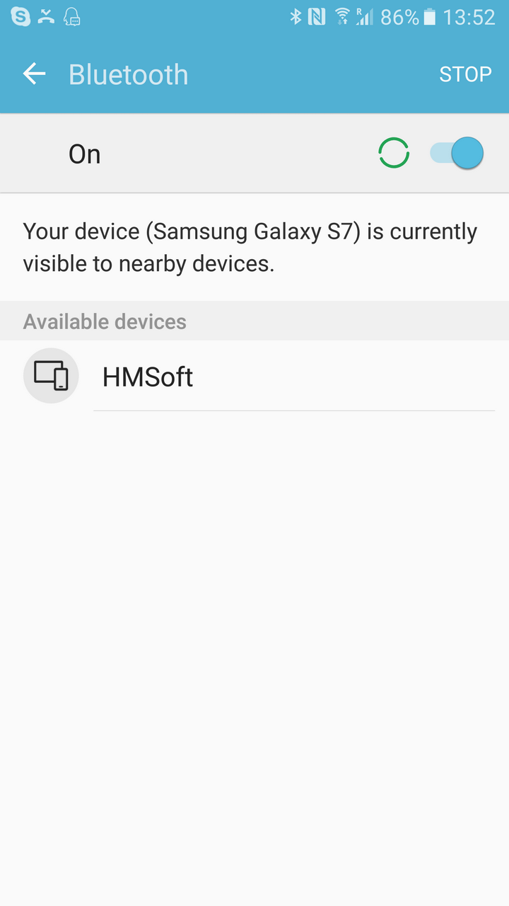
Depending on your Android device and the version of Android you are running the HM-10 may or may not show up when searching for Bluetooth devices under the Android Settings.
Samsung S7 with Android 6.0.1 – Finds the HM-10 and allows pairing.
Sony Z3 Compact running Android 4.4.4 – Finds the HM-10 and allows pairing.
Huawei honor pro 4 running Android 4.4.4 – Does not find the HM-10
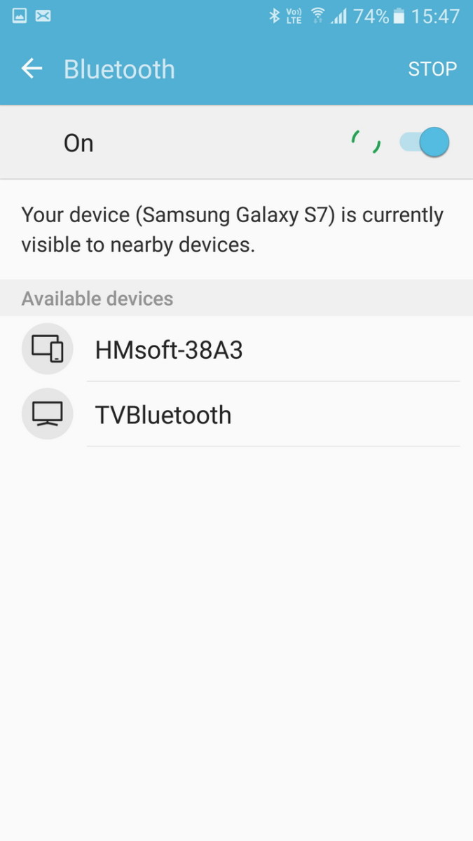
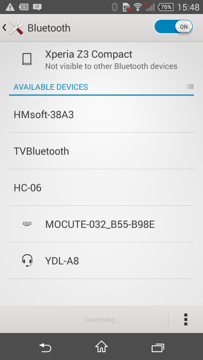
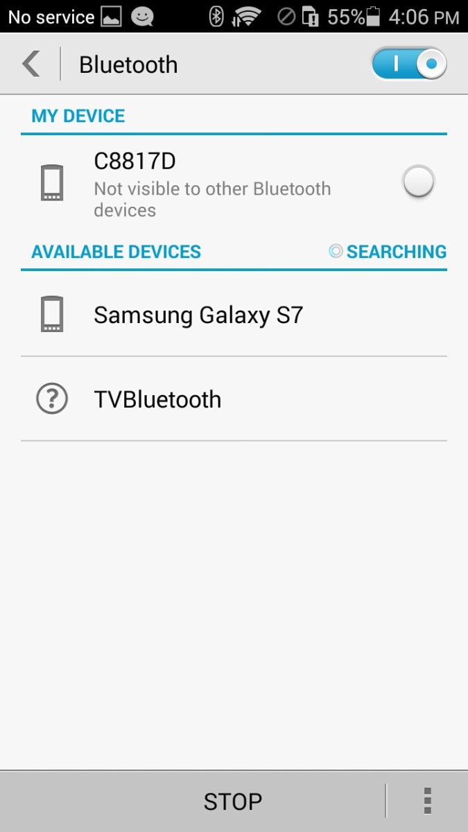
Using the system Bluetooth scan function, the Samsung S7 and the Sony Z3 Compact find the HM-10 but the honor Pro 4 does not. When using a BLE app all phones can find the HM-10.
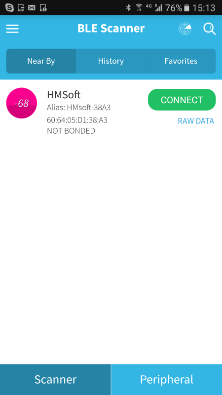
If you device does not find the HM-10 under Bluetooth settings, try using the BLE Scanner app.
To connect to the HM-10 and to read the services and characteristics we need to use a BLE app. Here I am using BLE Scanner. There are many other similar apps available such as B-BLE.
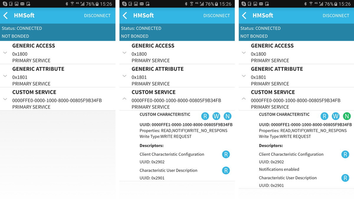
Reading the characteristics of the HM-10 using using BLE Scanner
Open the BLE Scanner app and find the HM-10. Tap the CONNECT button to get the app to connect to the HM-10 and start reading its properties.
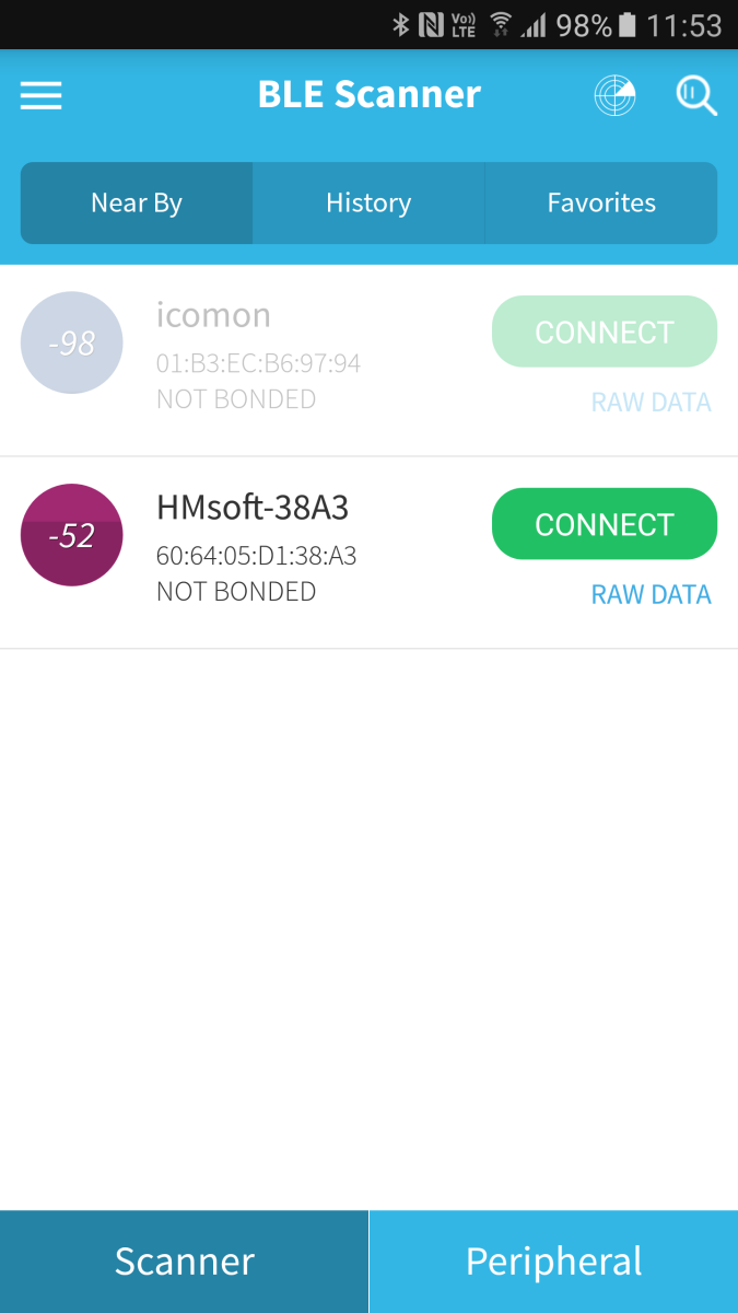
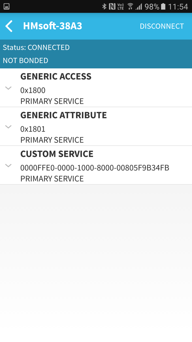
Clicking the small down arrows will expand the services and display the characteristics.
R = Read value
W = Write Value
I = Toggle indications on and off
N = Toggle notifications on and off
Tapping one of the ![]() labels will read the characteristic value. For example, under Device Name, tapping the
labels will read the characteristic value. For example, under Device Name, tapping the ![]() reads and then shows the device name value.
reads and then shows the device name value.
Under Custom Service you can see the HM-10s default service and characteristic values. You can also see that the HM-10s custom characteristic has Read, Write, and Notify attributes.
I mentioned earlier that BLE is all about services and characteristics and the HM-10 works by setting the value of a custom characteristic to match the value of the data to be transmitted (the data received via the serial connection). This can be seen when using the BLE Scanner app.
Send And Receive Data Using A BLE Scanner App
You can use an Arduino and the Aruino IDE to send and receive data to a BLE Scanner app that is connected to a HM-10.
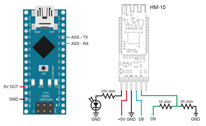
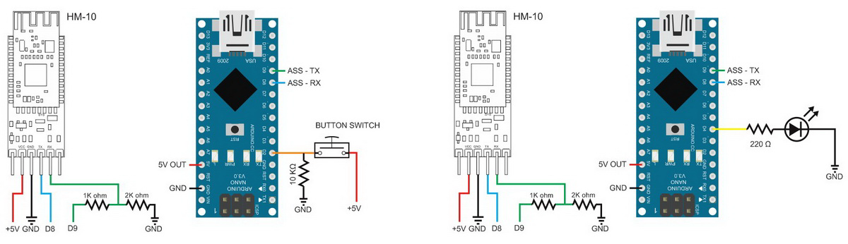
First connect the HM-10 to an Arduino and power on.
Circuit
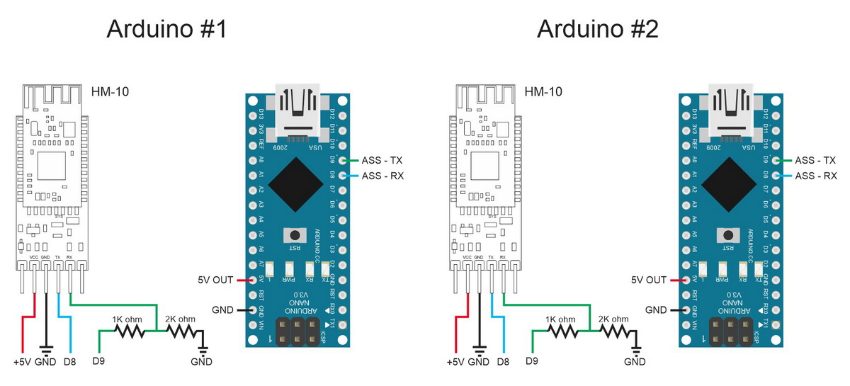
Connect the modules as per the following:
– HM-10 TX pin to Arduino D8
– HM-10 RX pin to a voltage divider and then to Arduino D9*
– HM-10 GND to GND
– HM-10 VCC to +5V
*The pins on the actual HM-10 (the small daughter board) are 3.3v only. They are not officially 5v tolerant so use a voltage divider or something else to bring the voltage down to 3.3v.
I am using AltSoftSerial to talk to the modules. AltSoftSerial uses pin D9 for transmit and pin D8 to receive. You will need add the AltSoftSerial library to the Arduino IDE before you can compile the below sketches.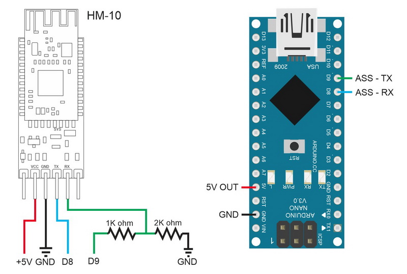

The HM-10 is a 3.3v device. The breakout board converts the +5v vcc to 3.3v to power the HM-10 but the RX pin is still 3.3v. Therefore, we need to bring down the Arduinos 5V TX pin to 3.3V. A simple way to do this is by using a voltage divider made from 2 resistors. I use a 1k ohm resistor and a 2k ohm resistor. 1K+2K = 3K. 2K is 2 thirds of 3K and 2 thirds of 5V is 3.3v.
The Arduino will see the 3.3v signal from the HM-10 TX pin as HIGH so we can connect the HM-10 TX pin directly to the Arduino RX pin (D8).
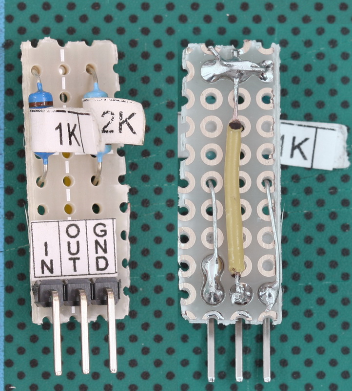
I am using a premade voltage divider.
I make a lot of this kind of breadboard circuits and I made many small breadboard modules. One of these is a voltage divider.
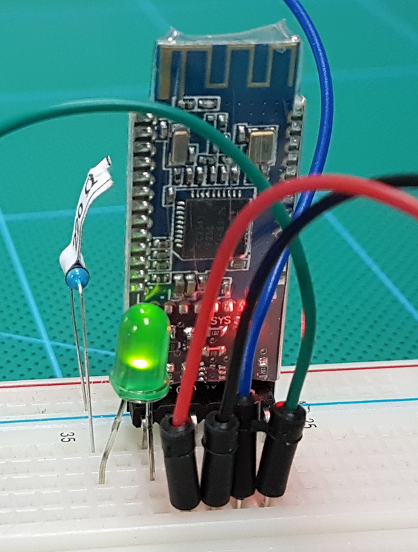
If you want to be special, you can place a LED on the STATE pin. Remember to add a resistor. The STATE pin is 3.3v when HIGH so using Ohm’s law we find that a 100ohm resistor would be OK. I didn’t have one on hand so I used a 220ohm one that I did have. Using larger resistors is OK but you shouldn’t use smaller ones.
The LED will blink in sync with the on board LED.
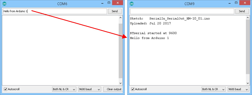
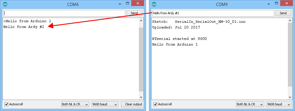
Serial Sketch
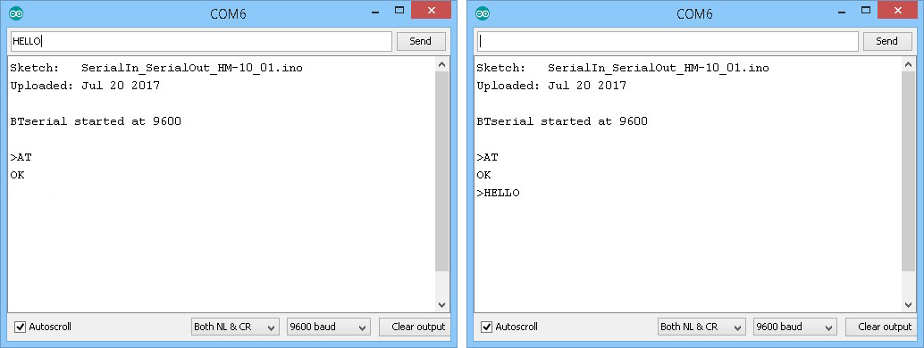
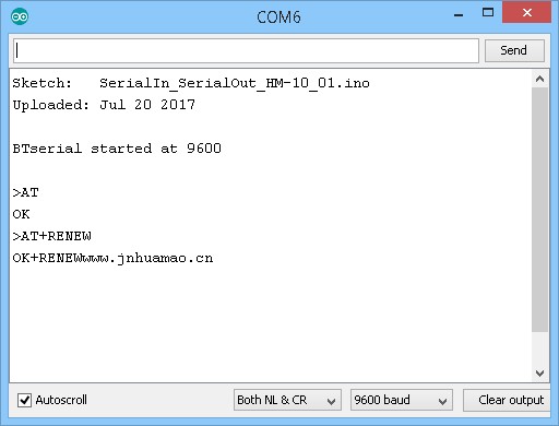
After building the circuit upload the following sketch. This is a simple serial in, serial out program. Whatever the Arduino receives from the serial monitor it relays to the HM-10. What ever it receives from the HM-10 it copies to the serial monitor.
I am using a HM-10 with an older firmware that likes 9600 but does not like end of line characters* (newline and carriage return (/n/r)) and normally you would not add them to commands. Here I am using them but noted that although the sketch prints the characters in the serial monitor it does not send them to the HM-10. This help make the examples easier to read.
*Later firmwares add free style line endings (add or not add /n/r). V700 onward uses a default baud rate of 115200.
The sketch uses AltSoftSerial which will need to be added to the Arduino IDE or copied to the library folder before you can compile.
// SerialIn_SerialOut_HM-10_01
//
// Uses hardware serial to talk to the host computer and AltSoftSerial for communication with the bluetooth module
//
// What ever is entered in the serial monitor is sent to the connected device
// Anything received from the connected device is copied to the serial monitor
// Does not send line endings to the HM-10
//
// Pins
// BT VCC to Arduino 5V out.
// BT GND to GND
// Arduino D8 (SS RX) - BT TX no need voltage divider
// Arduino D9 (SS TX) - BT RX through a voltage divider (5v to 3.3v)
//
#include
AltSoftSerial BTserial;
// https://www.pjrc.com/teensy/td_libs_AltSoftSerial.html
char c=' ';
boolean NL = true;
void setup()
{
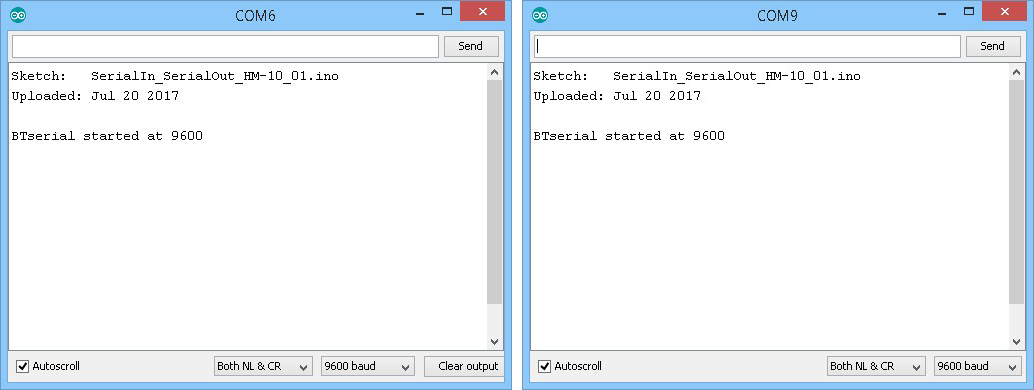
Serial.begin(9600);
Serial.print("Sketch: "); Serial.println(__FILE__);
Serial.print("Uploaded: "); Serial.println(__DATE__);
Serial.println(" ");
BTserial.begin(9600);
Serial.println("BTserial started at 9600");
}
void loop()
{
// Read from the Bluetooth module and send to the Arduino Serial Monitor
if (BTserial.available())
{
c = BTserial.read();
Serial.write(c);
}
// Read from the Serial Monitor and send to the Bluetooth module
if (Serial.available())
{
c = Serial.read();
// do not send line end characters to the HM-10
if (c!=10 & c!=13 )
{
BTserial.write(c);
}
// Echo the user input to the main window.
// If there is a new line print the ">" character.
if (NL) { Serial.print("\r\n>"); NL = false; }
Serial.write(c);
if (c==10) { NL = true; }
}
}
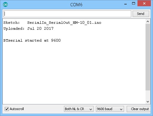
Upload the sketch and open the serial monitor.
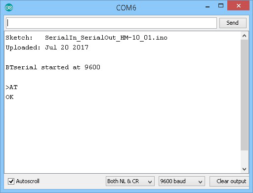
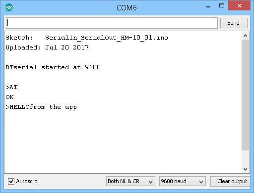
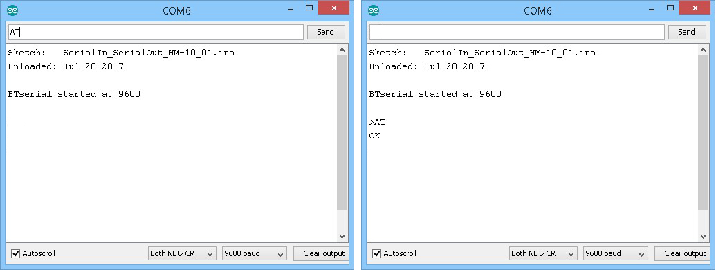
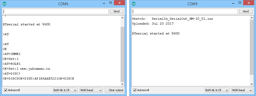
Use the “AT” command to confirm communication is working. If it is the HM-10 will reply with an “OK”
Now, in the BLE Scanner app, connect to the HM-10 by tapping the CONNECT button.
Open up the “CUSTOM SERVICE” section and turn notifications on by tapping the ![]() icon.
icon.
Now, what ever you type in the serial monitor should appear as the value of the custom characteristic within the BLE Scanner app
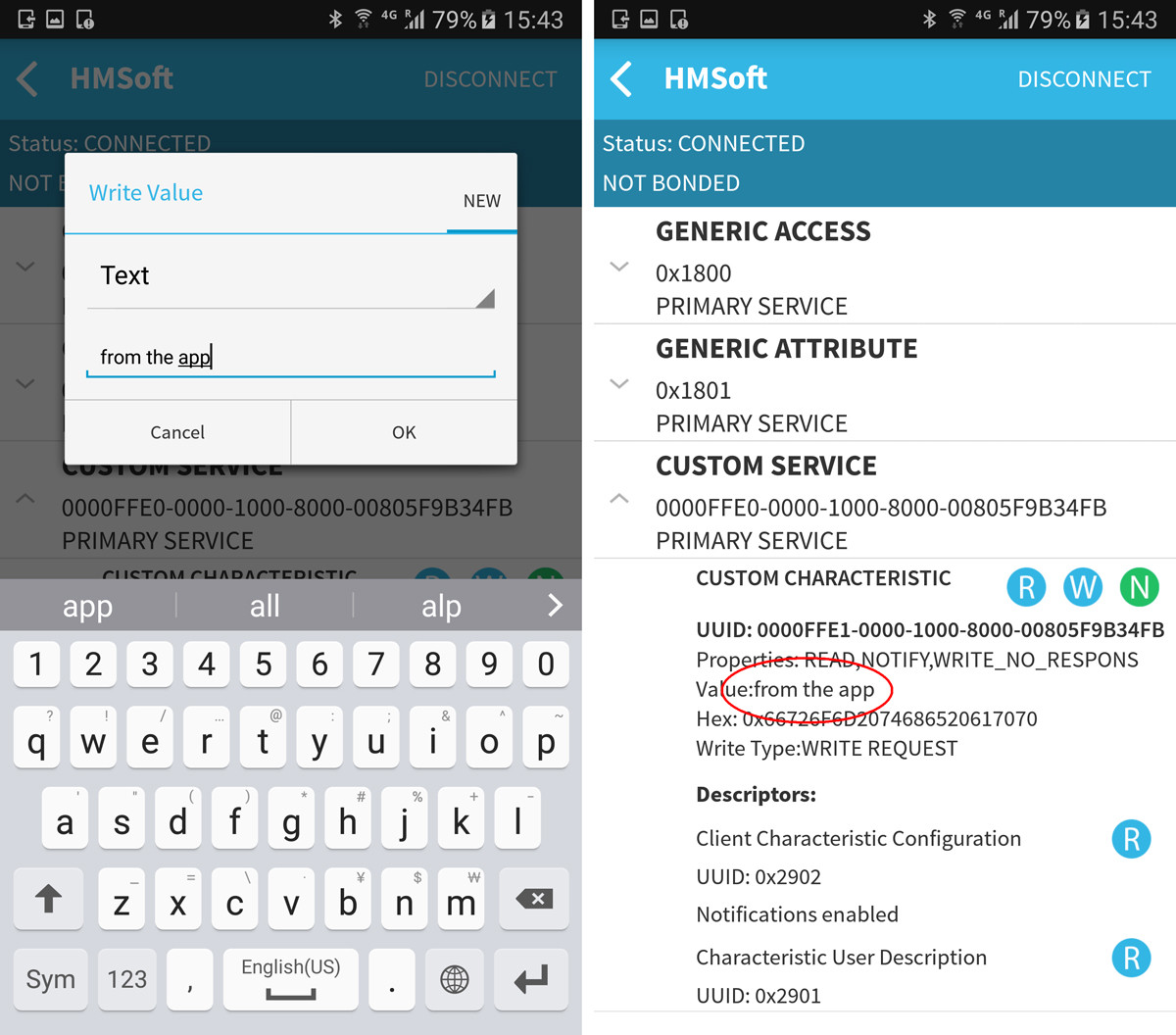
To send text from the app to the serial monitor, tap the ![]() Write icon and enter something in the popup text box. You will notice that the value of the custom characteristic changes to whatever you typed. The text should also appear in the serial monitor.
Write icon and enter something in the popup text box. You will notice that the value of the custom characteristic changes to whatever you typed. The text should also appear in the serial monitor.
Arduino Talking To A HM-10
Next we try using AT commands.
Note: AT commands only work when the HM-10 is not connected. After a connection is made the commands are treated as data. “AT” is the exception, the “AT” command breaks the connection.
Circuit
Same circuit as before,
– HM-10 TX pin to Arduino D8
– HM-10 RX pin to a voltage divider and then to Arduino D9*
– HM-10 GND to GND
– HM-10 VCC to +5V
HM-10 AT Commands: Using the Arduino’s serial monitor to talk to the HM-10
Open the serial monitor and you should see something similar to:
The HM-10 requires commands to be in upper case and, depending on the firmware version, normally without line end characters added. Here the sketch takes care of the line end characters for us. It does not send them to the Bluetooth module but will print them when echoing the command to the serial monitor main window. This is not really required but it means the commands will be on individual lines and be easier to read in the following examples. Normally, when working with the HM-10, everything is printed on one line.
Remember when using other sketches or a USB to serial UART adapter to set line endings to “No line ending” at the bottom of the serial monitor.
At the bottom of the serial monitor, set the baud rate to 9600 and using the above sketch means we can have line end characters selected:![]()
To see if the connections are correct we use the “AT” command. The “AT” command is used to confirm communication is working and all it does is return an “OK”. “AT” can also be used to break an active connection.
Enter “AT” (no quotes) in the text box and click Send. If everything is working you should see “OK”.
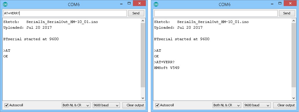
To check what firmware the HM-10 has, use AT+VERR?
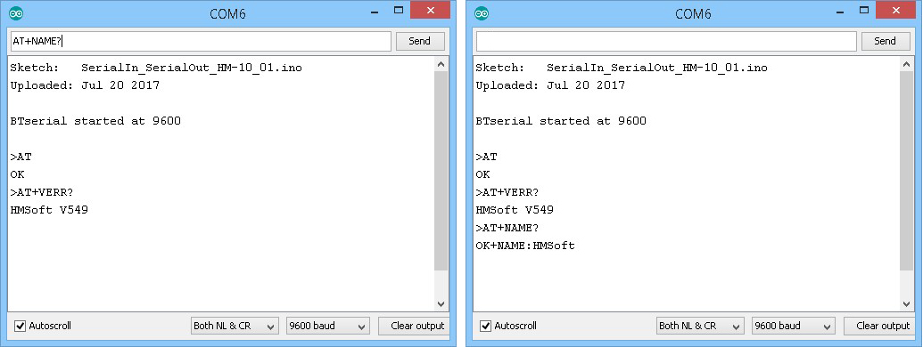
To check the modules name use AT+NAME?, or use an Android device and search for Bluetooth devices. The default name is HMsoft.
This only works when the HM-10 is in Salve/Peripheral mode.
When in Master/Central mode it does not broadcast its name.
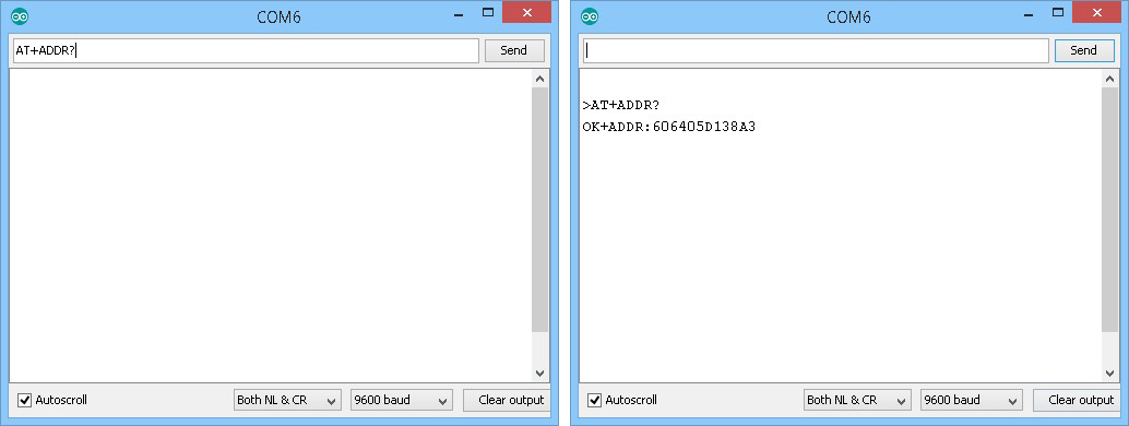
To get the modules address, use AT+ADDR?
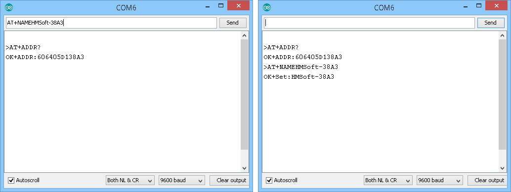
Change the name using AT+NAME.
Later I will be using 2 HM-10s and changing the names will help identify which is which. As you can see from the below I have changed the name to HMsoft-38A3. The “38A3” are the last 4 digits of the mac address.
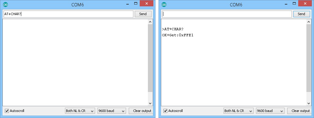
To get the modules Bluetooth characteristic, either use AT+CHAR?
You can also use a BLE scanner app.
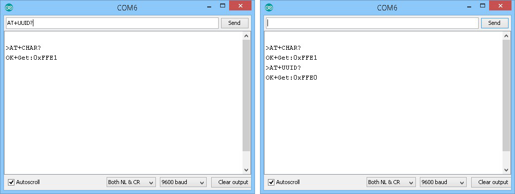
To find the UUID use AT+UUID? This returns OK+Get:0xFFE0.
Common AT commands
Here is a list of the main AT commands. Remember that commands should be in uppercase and not include line ending characters (\r\n) unless you are using the above sketch in which case it does not matter if you include line end characters or not.
| AT | Test Command or Disconnect Command | If the module is not connected to a remote device it will reply: “OK” If the module has a connection then the connection will be closed. If the notification setting is active, the module will reply with “OK+LOST” |
| AT+NAME? | Query the name | Returns the name the module broadcasts such as HMsoft. |
| AT+NAMEnewname | Change the name of the module | Changes the name broadcast by the module. For example AT+NAMEmyBTmodule changes the name to myBTmodule. The maximum length for a new name is 12 characters. |
| AT+ADDR? | Queries the HM-10s mac address | Returns the address as a 12 digit hexidecimal number. For example, OK+ADDR:606405D138A3 |
| AT+VERS? AT+VERR? | Queries the firmware version number | For example: HMSoft V540 |
| AT+RESET | Restarts the module. | Returns OK+RESET Will close an active connection while restarting. |
| AT+RENEW | Restores the default factory settings. | A quick and easy way to reset all settings. |
| AT+BAUD? | Query the baud rate used for UART serial communication. This is the speed a host device like an Arduino uses to talk to the BT module. It is not the the speed used to send wireless signals between different modules. | Returns the value 0-8, for example, OK+Get:0 0 – 9600 1 – 19200 2 – 38400 3 – 57600 4 – 115200 5 – 4800 6 – 2400 7 – 1200 8 – 230400 The default setting is 0 – 9600. Remember that both devices, the Arduino and the HM-10 need to use the same baud rate. Garbage characters are usually a sign of mismatched baud rates. |
| AT+BAUDx | Set the baud rate used for UART serial communication. | x is a value from 0 to 8. See the above for wwhat value represents which baud rate. Take care when using with an Arduino. The maximum baud rate the Arduino serial monitor allows is 115200. If you set the baud rate to 230400 with AT+BAUD8 you wont be able to talk to the module. |
| AT+NOTI | Set the notification status | If notifications are turned on, the HM-10 will reply to commands with a confirmation message or send out a message when certain events take place, like “OK” for the AT command and “OK+LOST” when a connection is broken. |
AT+NOTI0 – turn off notifications
AT+NOTI1 – turn on notificationsAT+NOTI?Query the notification statusReturns either 0 or 1:
0 – notifications are off
1 – notifications are onAT+PASS?Query the password used for pairing.Replies with a 6 digit number like “OK+Get:123456” or whatever the current password is.AT+PASSSet a new password.The password must be 6 characters long..
AT+PASS123456 sets the new password to 123456AT+ROLE?Query the current Role; Master or SlaveAT+ROLE? returns either 0 or 1.
0 = Slave or Peripheral
1 = Master or Central.
The default setting is 0 (Slave).AT+ROLExSet the device role. x is 0 or 1.To change to Slave/Peripheral mode use AT+ROLE0. This will return OK+Set:0
To change to Master/Central mode use AT+ROLE1. This will return OK+Set:1
AT+ROLEx mat require a reset before the changes take place.AT+IMME?Query the start modeAT+IMME? returns either 0 or 1.
0 = Connect immediately (assuming a previous connection has been applied
1 = Wait for a connection command before connecting (AT+START, AT+CONN, AT+CONL
The default setting is 0 (connect on start).AT+IMMExSet the start up modeAT+IMME0 sets auto connect on start*
AT+IMME1 sets manual connection mode
AT+IMMEx is often used together with AT+ROLEx
AT+IMMEx mat require a reset before the changes take place.AT+RESETRestarts the module
AT+RENEWResets the module to the factory settings
*If there are no previous connections, HM-10s will auto-connect to any other HM-10 available (normally the one with the strongest signal). The HM-10 (by default) remembers the address of the last module it was connected to and if there is stored a previous connection this will take priority when the HM-10 is retrying to auto-connect.
For a full list of AT commands see the official data sheets:
Scanning for other HM-10s
For this example I am using 2 HM-10s; one connected to an Arduino as before, and a second simply powered.
To ensure I am using the default factory settings I have used AT+RENEW:
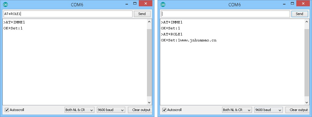
By default the HM-10 is in Slave or Peripheral mode and to scan for other devices we need to put it in to Central or Master mode. We do this using the AT+ROLE command.
AT+ROLE? queries what mode the device is in.
AT+ROLE0 sets the module to Peripheral mode.
AT+ROLE1 sets the module to Central mode.
In older versions of the firmware, AT+ROLE required the HM-10 to be reset either by cycling the power or by using the “AT+RESET” command. In the newer firmwares it auto resets itself (evident by the “www.jnhuamao.cn” welcome message).
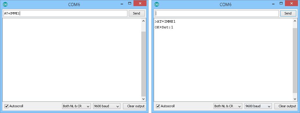
Before we switch to Master/Central mode we need to turn off auto connect with AT+IMME. AT+IMME has 2 options; AT+IMME0 and AT+IMME1.
AT+IMME0 sets the module to auto connect on start up. This is the default mode.
AT+IMME1 sets the module to wait until it receives one of the connection AT commands (AT+START, AT+CON, and AT+CONNL) before attempting to make a connection.
If the modules are set to auto-connect, when we enter AT+ROLE1 the modules will auto connect before we get chance to enter the AT+IMME1 command (they auto-connect fairly quickly).
Use AT+IMME1 to stop the HM-10 auto-connecting.
Use AT+ROLE1 to put the HM-10 in to Central mode.
If you are using an older firmware you will now need to reset the module by either cycling the power or by using the AT+RESET command. If you forget to reset the AT+DISC command will not work.
To scan for other HM-10 modules use the Discover command AT+DISC?
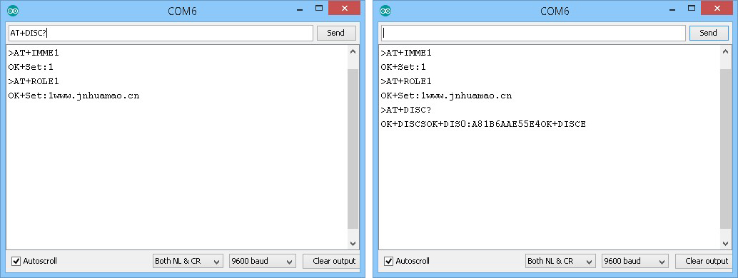
If the scan finds other HM-10s it will return the addresses of the modules found.
The “OK+DISCE” statement shows that the scan has Ended.
OK+DISCSOK+DIS0:A81B6AAE55E4OK+DISCE
The results are stored in a list, the list starts at position 0, and can be used to make a connection using the “AT+CONNx” command rather than having to use the full address. The x is the index number or list position value.
If the HM-10 only finds one module the result will be stored at index 0 and “AT+CONN0” can be used to connect to it. When more than one module is found the addresses will be stored in the order they are discovered.
After a connection is made the list is cleared. This means if you break the connection you need to use the “AT+DISC?” command again. For experimenting with AT commands using “AT+CONNx” is fine, but I suggest using the full address to make sketches more robust and easier to write.
Note: AT+DISC? will only find HM-10s that are set to Peripheral mode. You cannot scan for modules set to Central mode.
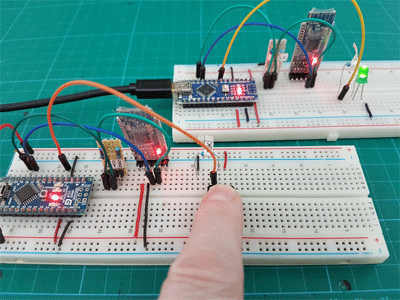
Arduino to Arduino Communication Using HM-10s
Connecting 2 Arduinos using 2 HM-10s is fairly easy. It is straight forward to make a connection and once the connection is established the HM-10s UART layer does all the work for you. The UART layer does mean you have no control over the actual BLE details though. To make a connection, all we need to do is set the main module to manual connection, set to Central mode, and then use the connection command AT+CON. Once connected the HM-10 transfers data by setting the value of a custom characteristic to the data you are sending. The receiving device then reads the value.
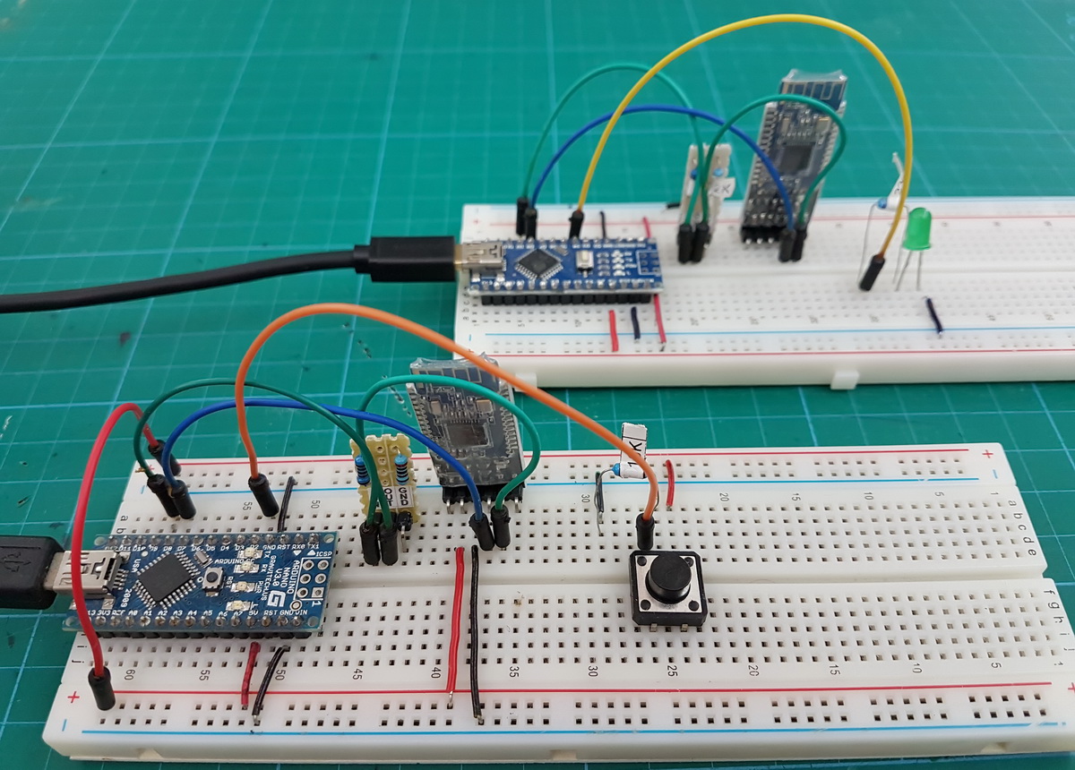
For this example I have 2 Arduinos and each Arduino is connected to a HM-10. Both are wired up exactly the same.
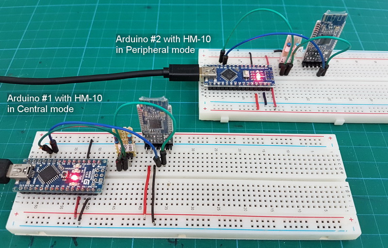
and if you are wondering where the second HM-10 is getting power from; the connections are round the back.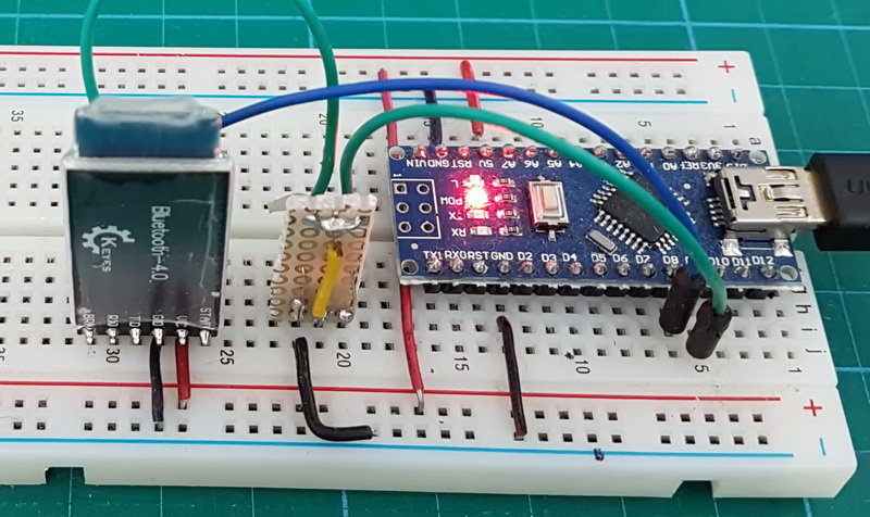
I am using 2 different Arduino IDEs. Version 1.82 as the main IDE and version 1.63 as the secondary IDE. This gives me 2 serial monitors. The Arduino on COM6 is #1 and the Arduino on COM9 is #2.
HM-10 to HM-10 manual connection
To make a connection we:
Set the second module to Peripheral mode (the default setting),
Set the main module to manual start mode using “AT+IMME1”.
Then set the main module to Central mode with “AT+ROLE1”.
Then use “AT+CON” to connect. Of course you need to know the address of the second module which can be found using “AT+DISC?”.
Now we have the address of the second HM-10 we can connect using the address or the list index. Here I am using the address and so the command is “AT+CONA81B6AAE5221”. You would need to change the address to suit the modules you are using.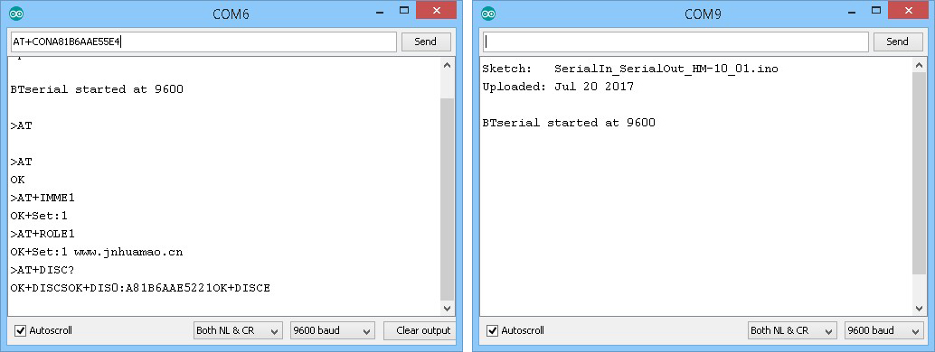
If the connection is successful we get “OK+CONNA” and the LEDs on the HM-10s stop flashing and become steady on.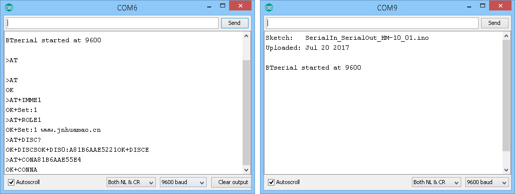
Now, everything entered in one serial monitor is transmitted to the other.
HM-10 to HM-10 automatic connection
The HM-10 can automatically connect on start up without using a connection command. When there are 2 or more modules and one is in Central mode it will search and connect to another HM-10. This is fully automatic and you have no control over which module it connects to although it would normally pick the one with the strongest signal. Of course, if there are only 2 modules it does not matter. When you have only 2 modules, set one to Peripheral mode and the other to Central mode. They should now connect automatically. Nothing else is required.
If there has been a previous connection, the device last connected to will take priority over other modules. After you have made a manual connection, break the connection (cycle the power) and when ready enter “AT+IMME0” (this turns on auto connect). Then reset the module by either cycling the power or using the “AT+RESET” command. The modules should now auto connect even when there are addition HM-10s in range.
The “AT+IMME1” command stops the auto connect happening. Remember that you cannot use AT commands while there is an active connection (the commands are treated as data) (except “AT” which breaks a connection) so to enter AT commands you need to turn of the remote module and reset the Central one.
HM-10 to HM-10: Turning an LED on and off
We now try LED remote control. This is a very simply example, when a button switch is pressed a remote LED comes on. When the button switch is released the LED goes out.
On Arduino #1 we add a button switch to D2 and on Arduino #2 we add a LED to D4.
The switch on Arduino #1 is pulled down with a 10K resistor. This means pressing the button switch makes the Arduino pin go LOW to HIGH.
The LED on Arduino #2 is connected inline with a 220 ohm resistor (330 ohm is also OK).
The sketch on the master Arduino uses 3 AT commands to set up the Central HM-10 and start the connection. These are the same commands we used in the manual connection example above.
BTserial.print("AT+IMME1" );
delay(1000);
BTserial.print("AT+ROLE1" );
delay(1000);
BTserial.print("AT+CONA81B6AAE5221" );
delay(1000);
This is not really the best solution but it works and it keeps the example easy to understand. Of course, if the HM-10 is already in Central mode and in manual start mode the first 2 commands are not required. The delays allow time for the replies. You could, if you wished, check for the correct reply before moving to the next command. Change the address to suit the modules you are using.
If you are using an older firmware you will need to add a “AT+RESET” command after the “AT+ROLE1”.
You could do away with these commands by using the auto-connect mode.
After this, the sketch checks the status of the pin connected to the button switch and if it has changed sends out 1 of 2 commands.
- LOW to HIGH. The button switch has been pressed so we want to turn on the LED. This is done by sending a “1” to the remote module.
- HIGH to LOW. The button switch has been released so we want to turn off the LED. This is done by sending a “0” to the remote module.
Note that we are sending ascii “1” and ascii “0” not the value 1 and the value 0.
// Very simple debouce.
boolean state1 = digitalRead(switchPin); delay(1);
boolean state2 = digitalRead(switchPin); delay(1);
boolean state3 = digitalRead(switchPin); delay(1);

if ((state1 == state2) && (state1==state3))
{
    switch_State = state1;

    if (switch_State != oldswitch_State)
    {
          if ( switch_State == HIGH) { BTserial.print("1" );  Serial.println("1"); }
          else                       { BTserial.print("0" );  Serial.println("0"); }

          oldswitch_State = switch_State;
    }
}
The secondary Arduino simply checks for a “1” or a “0” and if it finds one of them it either turns the LED on or turns the LED off.
void loop()
{
    // Read from the Bluetooth module and check if it is a command
    if (BTSerial.available())
    {
        c = BTSerial.read();

        // 49 is the ascii code for "1"
        // 48 is the ascii code for "0"
        if (c==49)   { digitalWrite(LEDpin,HIGH);   }
        if (c==48)   { digitalWrite(LEDpin,LOW);    }
        Serial.println(c);
    }

}
Here are the full sketches.
On the first Arduino we have HM-10_Example_01_simpleLED_Central.
// HM-10_Example_01_simpleLED_Central
//
//  Simple remote control using HM-10s: LED on. LED off
//
//
//  Pins
//  BT VCC to Arduino 5V out.
//  BT GND to GND
//  Arduino D8 (ASS RX) - BT TX no need voltage divider
//  Arduino D9 (ASS TX) - BT RX through a voltage divider
//

#include
AltSoftSerial BTserial;

byte switchPin = 2;
boolean switch_State = LOW;
boolean oldswitch_State = LOW;

void setup()
{
    Serial.begin(9600);
    Serial.print("Sketch:   ");   Serial.println(__FILE__);
    Serial.print("Uploaded: ");   Serial.println(__DATE__);
    Serial.println(" ");

    BTserial.begin(9600);
    Serial.println("BTserial started at 9600");
    Serial.println(" ");

    pinMode(switchPin, INPUT);

    // connect to the remote Bluetooth module
    BTserial.print("AT+IMME1" );
    delay(1000);
    BTserial.print("AT+ROLE1" );
    delay(1000);
    BTserial.print("AT+CONA81B6AAE5221" );
    delay(1000);

}

void loop()
{
    // Very simple debouce.
    boolean state1 = digitalRead(switchPin); delay(1);
    boolean state2 = digitalRead(switchPin); delay(1);
    boolean state3 = digitalRead(switchPin); delay(1);
    if ((state1 == state2) && (state1==state3))
    {
        switch_State = state1;

        if (switch_State != oldswitch_State)
        {
              if ( switch_State == HIGH) { BTserial.print("1" );  Serial.println("1"); }
              else                       { BTserial.print("0" );  Serial.println("0"); }

              oldswitch_State = switch_State;
        }
    }
}
On the second Arduino we have HM-10_Example_01_simpleLED_Peripheral.
// HM-10_Example_01_simpleLED_Peripheral
//
//  Pins
//  BT VCC to Arduino 5V out.
//  BT GND to GND
//  Arduino D8 (ASS RX) - BT TX no need voltage divider
//  Arduino D9 (ASS TX) - BT RX through a voltage divider
//

#include
AltSoftSerial BTSerial;

char c=' ';
byte LEDpin = 4;

void setup()
{
    Serial.begin(9600);
    Serial.print("Sketch:   ");   Serial.println(__FILE__);
    Serial.print("Uploaded: ");   Serial.println(__DATE__);
    Serial.println(" ");

    BTSerial.begin(9600);
    Serial.println("BTserial started at 9600");
    Serial.println(" ");

    pinMode(LEDpin, OUTPUT);
    digitalWrite(LEDpin,LOW);
}

void loop()
{
    // Read from the Bluetooth module and check if it is a command
    if (BTSerial.available())
    {
        c = BTSerial.read();

        // 49 is the ascii code for "1"
        // 48 is the ascii code for "0"
        if (c==49)   { digitalWrite(LEDpin,HIGH);   }
        if (c==48)   { digitalWrite(LEDpin,LOW);    }
        Serial.println(c);
    }

}
The above works well but what happens when you reset Arduino #1 when there is an Active connection? The LED comes on.
When you reset the Arduinos but not the HM-10s the connection remains active and the AT commands in the setup() function get sent as data and any “1”s in the data get recognised as LED Commands. There is a few things you can do to stop this happening.
- Before sending the AT commands, send a welcome message to see if there is an active connection. The remote device would reply to the message.
- Check the HM-10 STATE pin before sending the AT commands. The STATE pin is HIGH when there is a connection.
- Set the modules to auto connect and get rid of the AT commands. In my opinion this is the best option.
I leave this to you to implement.
Using The HM-10 With non-HM-10 Modules
Starting with firmware 5.42, Jinan Huamao changed how the HM-10 interacted with non Jinan Huamao modules. Prior the 5.42 the HM-10 connected and communicated with other modules just fine.
Using the later firmwares, I have so far had limited success with connecting HM-10s to the other UART BLE modules like the AT09 and BT05. The HM-10 will connect to the other module and data can be sent from the HM-10 to the remote device but I cannot receive data from the remote device. I had thought that using the self study function (AT+COMP1) meant that the HM-10 read the remote device characteristic’s properties and so meant that notifications would work. This does not seem to be the case though. I get the same results using the self learn mode and not using it. I think there is an issue with the HM-10 reading the other devices notifications.
Update: Additional commands were added in firmare v700 to help with using the HM-10 with other types of modules. I haven’t had chance to try them yet. See the readme that comes with the firmware download for details.
-Added new function used to support different brand BLE device
-Added AT+FINDSERVICES? command
-Added AT+FINDALLCHARS? command
-Added AT+NOTIFY_ON command
-Added AT+NTOIFYOFF command
-Added AT+READCHAR command
-Added AT+CHAR command
-Added AT+READDATA command
-Added AT+READDESC command
-Added AT+SEND_DATA command
HM-10 Downloads
HM-10 data sheet V5.50
HM-10 data sheet V5.45
Official update firmware guide
HM-10 Self-learning guide. Requires fw v5.42 or later.
HM-10 Sketches
Sketch: SerialIn_SerialOut_HM-10_01.ino
Sketch: HM-10_Example_01_simpleLED
Sketch: HM-10_Example_03_MODE2_LED
Sketch: HM-10_Example_04A_RemoteLightSensor
For what its worth, I’d like to add a few observations which others may appreciate.
I’ve been working with a couple of Chinese clones (I’d like to call imitations).
They are sold as HM-10’s but we all know the story about this by now.
In the terminal, I extracted the firmware versions to be Bolutek- VER 3.0.6
Both my LG G5 and an older Samsung G4 would see the BLE, but were refused connections via bluetooth on the phones.
And so I upgraded the firmware to ver. 540, and bingo!…both phones can now connect.
Going further, I tried upgrading the firmware as Martyn suggests…
The upgrades went well, however EVERY other version of firmware beyond 5.4 would not allow my phones to connect.
And so, I went back to pins 7,8,and 11 via the arduino nano on the cmd prompt to downgrade back to 5.4
All AT commands work and a connection can be made by both phones.
Kudo’s to Martyn for an outstanding site and such well documented info on these little wonders..
I’m anxiously waiting for the control panel app to be BLE compliant…
That will indeed be the cats miou!
Cheers,
Perry
After 5.40 Jinan Huamao changed how the HM-10 interacts with non- Jinan Huamao modules and introduced Self Learning Mode. I haven’t done anything with this (been meaning to just never got round to it) and as far as I can tell you need to match the UUIDs with the remote module and the the HM-10 will find out what properties the characteristic has (such as read/write/notify).
With fw 5.40 and before this appears to be the default behavior.
Thanks for this incredible post!
My laptop is running Windows 7 64 bits, and supports bluetooth 2.0 instead of 4.0 BLE. Therefore, I will need a USB dongle with bluetooth 4.0 BLE. Do you think any dongle with bluetooth 4.0 will work? I’ve found this one:
https://produto.mercadolivre.com.br/MLB-773422776-mini-adaptador-bluetooth-csr-verso-40-dongle-ps3-ps4-xbox-_JM?flash=f3be7f8559e3a69b014438df8f265d89ffcc37ce&noIndex=true
Thanks again!
Fernando
I cannot guarantee but….
I think any will do and the one you linked to looks to be the same as the one I use on my desktop.
Hi Martyn, thank you for your helpful tutorial on HM-10 Module. I have a module with the TI CC2541 chip but without the external 32kHz crystal connected to an Arduino UNO that reads a sensor. When arduino reads a data, sends it to the bluetooth module but what the reads on my BLE Scanner is often different from what arduino sent. Sometimes BLE Scanner receives a part of the initial string sometimes data are wrongs. Can it be due to the different firmware?
Thanks
Frank
Hi Martyn!
What about your “HM-10 as an iBeacon” chapter???? 1 year waiting…. and counting!
Regards!
Yeah, sorry for the delay. After creating a couple of beacons I realized I had no use for them and didn’t do a write up…
Have a look at the Blue Luminance guide at
http://www.blueluminance.com/HM-10-as-iBeacon.pdf
and instructables at http://www.instructables.com/id/make-iBeacon/ although it looks like the instructables is following the Blue Luminance guide.
Hey Martyn!
Thanks a lot for all the information on this post. Really helped!
One quick question:
Is there any advantage on having the second write-only characteristic activated? For example, can you achieve a higher-speed or more robust data transfer?
I’m sending packets of 100 bytes from my phone and some times it looks like HM-10 cannot keep pace (does not send the ACK message, [at least I don’t see it from the app]), so I was wondering if splitting the write and read in different services would help mitigate that.
Thanks in advance!
Cheers,
Eric
I haven’t really done a lot with the second characteristic and for the few projects where speed and data integrity were critical I used a different system.
I do suspect that the problem is likely to be with the UART interface though. I presume you are using UART, if so, what baud rate are you using? If it is fairly slow try increasing it. If using an Arduino, be wary of software serial. It does not like high speeds. If possible use hardware serial or at the very least AltSoftSerial.
Hi Martyn! Thank you very much for creating such a helpful resource!
I’ve looked through all the sections on your site and can’t find a clear answer to a question I have… I’d like to recreate the remote light sensor project above, but with a standalone HM11 module and using an android or iOS app to read the voltage value on the HM11 input pin (PIO3 it seems). Is this possible to do?
Regards,
Richard
I’m not at home so can’t check but…
The HM-11 can be used exactly the same as the HM-10 except it has less pins so the remote example above should work the same.
For the battery, check the data sheet. The HM-10/11 has the facility to put the voltage level in to a characteristic. Can’t remember which or how though.
It may also be worth while checking out the HM-sensor firmware. Again, I can’t remember the details but the docs are available on the Jinan Huamao website.
Thanks Martyn! It had occurred to me that using the HMsensor configuration might make it easier… I will flash the HMsensor firmware to the HM11 to see the difference. It is not the battery level that I want to transmit, simply a variable voltage on the input pin (it seems only PIO3 can be set up for this on the HM11). Perhaps it is my lack of knowledge of how to read the sensed pin data from the transmitted characteristic, but I can’t seem to read a varying voltage input to the HM11 using any of the iOS apps (HM10Control, Bluetooth Serial Pro, Liteblue, BLE Scanner etc.)
Update: Putting HM11 into Mode1 and using the AT+COL?? or AT+PIO?? command returns state changes on PIO3 pin (the only input enabled pin on HM11) at a rate set using AT+CYC[t], but does not recognise AT+ADC command. Suspect ADC function on HM11 is disabled – have emailed JNHuamao to confirm
Hi Martyl, I have been reading the comments here and think this comment best suited my question. I am wanting to advertise the Battery level in the response data. So that I can run AT+DISA? and then view MAC, RSSI, UUID and Battery level. I can’t seem to get this working.
I have set AT+BATC1, to allow BATT advertising in the response data, but yet it is not visiable via AT+DISA?
Could you maybe point me in the right direction so that I can advertise the BATT info in the response data of AT+DISA?
Any help would be appreciated
DISA doesn’t add the battery information. DISA is used to scan (or discover) other BLE devices) only.
It has been a while since I used the HM-10 but if I remember correctly the battery information is transmitted only in the advertising data. It should be covered in the data sheet.
Hey,
I am trying to create a device that has HM10 to connect serially with my laptop via its built in Bluetooth.
My HM10 can pair with my laptop. However, I cannot send any data serially because I do not know how to setup my built in Bluetooth to act like a serial port.
I tried to create a new COMM port but it won’t find my HM10.
Any help please?
I presume you are using Windows. If not please ignore the below.
BLE on Windows requires additional software. It does not act the same as Bluetooth Classic which mimics a serial connection as so uses COM ports.
Try one of the BLE scanner apps such as LE Explorer at https://www.microsoft.com/en-us/store/p/bluetooth-le-explorer/9n0ztkf1qd98 or google “Windows BLE scanner”.
hi, i have a very simular problem. i used the app you mentioned, and i can get a connection on my windows 10 laptop. i also found out my build in bluetooth drivers are LE compatible. now the problem, when there is a connection, it doesnt show as a COM port in device manager. how can i get my hm10 (i have a real one, not a fake) to be recognized as a COM port?
Has anyone had any luck connecting to these things on Android 8.1?
I have a CC41-A clone, and my Pixel 2 nor my wife’s Pixel 1 (both on 8.1) won’t even find them in BLE scanning apps. I have been able to issue AT commands over the serial interface successfully via an Arduino, but no matter what I just can’t see it in Android. I’ve tried AT reset, changing the name, etc, but with no luck.
I thought I may have a dud unit with a bad aerial or something, but I fired up my RPi 3 and can actually see it when I scan with hcitool there. So it seems to be late version Android specific perhaps?
There seems to be a tiny bit of discussion around this online, but I can’t find anything particularly useful – eg http://www.electric-skateboard.builders/t/bluetooth-hm-10-not-discoverable-on-android-8-0-8-1-oreo
At this point I’m thinking I’ll just use an HC-05 or something and ditch BLE for my application, but it’s a bit of a pain as I’ll need to wait for more parts to arrive. Cheers!
It an issue with Android 8. There are still many problems reported with Android 8 in general and a quick google “android 8 ble not good” will return quite a few results. Google say they are working on a fix but the BLE issues were reported last year and the problems still persist.
In Android 8, you need to add the permission for Bluetooth scanning into your Android studio file.
For me, adding this to the original Bluetooth LE GATT example solved the problem:
https://github.com/schollp/BLEGattAndroid8
This is a great writeup, thanks a lot. I have one question left though. Is there a way for the bluetooth module to scan for smartphones it has been paired to before and auto connect to them the same way a bluetooth headset does? Somehow nobody was able to achieve it as far as my research shows.
I do not need to communicate with the smartphone, just connect to them automatically as an authentication process for a switch I want to trigger afterwards. Is there a way without using an android app for that?
This is not something I have done with 2 modules but not with a smartphone but I have some thoughts.
The phone, by default, is the master device. This means it is the phone that scans for the BT modules and connects when it finds a BT module it has previously been paired with. For the BT module to be the master device would require additional software on the phone.
Headsets use the HID profile which has different connection methods (such as auto connect) and I am not sure auto connect works with the HM-10. I haven’t tried though.
Great tutorial. I am using the HM-11 for a project and having terrible luck getting it working. The firmware on the HM-11 is V546.
I am trying to scan for BLE peripherals and iBeacons nearby but I am only able to find my devices if they are within about 1 foot. Once I move the device farther from that the HM-11 is unable to find it. I am using other HM-11’s and some nRF51822 boards for the peripherals/iBeacons.
To scan for peripherals:
AT+ROLE1 //set as master
AT+IMME1 //wait for commands after reset
AT+RESET //reset
AT+DISC? //start discovering
To scan for iBeacons:
AT+ROLE1 //set as master
AT+IMME1 //wait for commands after reset
AT+RESET //reset
AT+DISI? //start discovering
I have my power set at 6dbm (AT+POWE3) on the HM-11 central. I am using a 100ms advertising interval for the peripherals/iBeacons. I am still unable to find my peripheral/iBeacons further than about 1 foot away which is quite a problem. I am pretty sure that my hardware is good because I have tried it on multiple HM-11’s which I bought from Digikey.
Has anyone experienced this? Any help would be greatly appreciated.
Comment from Alex:
Thank you for your most informative posts, I have found them really useful and clear in my Arduino dabbling !
I am interested in trying to connect a DS18b 20 to pin 34 (?) of the HM10 and henceforth being able to include the temperature information in the advertising data, to be read by another HM10, connected to an Arduino (Mega).
Looking at your posts, it seems you know how this could be made to work, yet I haven’t seen exactly how to do this. Please could you point me in the right direction?
I was sort of assuming that one would use AT commands to instruct the HM10 to read the one wire data from the DS18b 20 on pin 34, then attach that data to the advertising data, but can this be done once, or does this AT command have to be sent to the remote HM10 every time you want the temp data?
I would be most grateful for any assistance you could provide.
Kind Regards
Alex
Look up AT+SENS? and AT+TEMP?
Hi, thanks very much for this page as it has been incredibly useful, although i have managed to get a few knock-off ‘HM-10s’ and have got two working and connecting. I have also managed to unknowingly purchase two MLT-BT05 chips, which look very similar to the HM-10s. I have ran your code and can get the serial monitor to display text i send through my phone to the MLT-BT05 however i can’t get the AT commands to work.
Using the normal AT commands there is no response though after playing about with it I’ve noticed it will respond to “ATAT” with OK (this will not break an active connection) and other doubled up commands such as “AT+HELP?AT+HELP?” wit ERR.
As far as i’m aware i have it set up correctly with 9600 BAUD and Both NL & CR (as the MLT-BT05 requires). Have you seen anything like this before or can you offer any advice. any help is much appreciated.
Cheers Ciaran
BT05’s generally have a Bolutek firmware. I don’t have separate posts for these but there is basic information in https://www.martyncurrey.com/bluetooth-modules/#BT05-A
After update Android OS from 7.0.x(Nougat) to 8.0.x(Oreo)
HM-10 is no longer discoverable on the phone at all.
Have anyone facing this problem?
I’m not sure is this Android OS bug or HM-10’s problem.
It’s a problem with Android 8
Hi i did what you describe but module don’t receive signal from phone and “AT” commands don’t work could you please help me?
more details there:
https://forum.arduino.cc/index.php?topic=535762.0
Hello! Would you like to tell me, what i need change? I used first scatch(simple serial) and ble scanner. I wrote in terminal and i saw value in ble scanner. I have a problem, when i wrote command AT, then i saw it in value without response.
are you trying to send AT commands over the BT connection?
I need to disconnect ble Scanner, and i will be happy?
I wrote AT without BT connection, but did’t get response
:-(
Hi, I don’t see the AT+PWRM on my AT-09, is there something I can do to fix it?
Very useful document!! Thanks for sharing !!!
how to scan the other hm-10 more than 2 devices in one time?
Hi. Tell me how to send the command 0x02 to the itag label https://al.aliexpress.com/popular/itag-bluetooth-tracer.html
given labels FC:58:FA:29:5C:8A, UUID 00002A06-0000-1000-8000-00805f9b34fb, immediate Alert 0x1802, Data 0x02 (high alert)?
Hi, thank you for your article. I have a problem that when I enter commands such as “AT+CON” OR “At+disc?” They output nothing
AT + VERS? working? you may need to flash hm-10.
Very helpful doc.Thank you.
Occasionally, I get a null character back at the end of the response to AT+RESET or AT+RENEW. It’s easy enough to add some code to throw it away, but do you know what’s causing it?
Thanks.
For the older firmware’s I haven’t come across this or I simply haven’t noticed.
If you are using a new module with the latest firmware (6.05 ) then it may be line end characters.
Would it possible to configure master device to switch among multiple Peripheral modules?
This is may be scenario if you need to read samples from multiple sensors from a central devices via bluetooth.
Thanks.
Using the HM-10 to would need to connect to each remote device in turn.
1 – connect to remote #1
2 – read data
3 – disconnect
4 – connect to remote #2
5 – read data
6 – disconnect
etc.
With other modules, like the RN4870, you could use advertisements. This would allow you to read data without making a connection.
Hi Martyn. Great post, Thanks.
I have been using hm-10 modules with firmware v540 for a long time with no problem. Recently I bought some modules with firmware v604 and all seem not to be able to wake through uart. Meaning, when I send a long text the module used to respond ok+wake and then I was able to send other at commands. Now the long text does not seem to return anything and the module stays in sleep mode. I downgraded to firmware v540 successfully but then the module was not discoverable in role0 and did not discover any other devices in role1.
Have you noticed this behaviour? Do you have any idea how to resolve this? I saw in a comment above that there is a 605 firmware. Where can I find this? I did not see it in Jinan Huamao website.
Thanks a lot!
I haven’t but I haven’t really used the HM-10s for a while. Contact Jinan Huamao support. I have found them quite helpful. Bare in mind that English is not their first language so keep the questions as clear and short as possible.
Hi Martin, It’s a very helpful post.
Is it possible to connect an hm10 as master to multiple hm10 slaves like a star or mesh network?
Not at the same time.
You need to connect to each node one at a time.
Connect, read data, disconnect.
Hi, Martin I am using arduino uno as USB to TTL Converter (by grounding RESET Pin of Arduino) for entering AT Commands. So, how to implement this (connect read and disconnect)
Hi, thanks for this very detailed and useful tutorial.
I can’t get READ property working in BLE Scanner APP. Garbage characters are always read: “_@9”.
How can I set the value of a READ property in HM10?
I tried sending chars on UART and then pressing R in Ble scanner, but the same “_@9” always appears.
Thanks a lot,
Dario
Hi all,
I tried AT+SLEEP in HM10. Led is switched OFF, but the module is still visible by BLE Scanner and connection can be established.
Is this the right behaviour? I expected the module to be switched off on Bluetooth.
After more tests.
– The value 0x7c010a5f4a39 is always reported to the APP when a read is attempted.
– If Notification is enabled in the APP, bytes sent by the device are correctly reported by the APP.
As reported in the “Product Parameters”, READ characteristic is not mentioned:
“Characteristic: Notify and Write (Modifiable use AT+UUID command)”
Is READ characteristic really supported?
Bye
Bye
i need one clarification…ls tz bluetooth will detect 100 beacons if i kpt
I am trying to connect HM-10 with VNA2-BT Adapter (BLE to CAN).I am unable to discover and connect VNA-BT.
i am issuing commands:
1.AT+IMME1
2.AT+ROLE1
3.AT+CONX
Can someone tell me how to establish the connection?
Hi martym
I m trying to connect my HM-10 module to smartphone via Bluetooth …….and I m also trying to get the RSSI value …… can you help me how to do it???
none of the command given below is working :
AT+RSSI?
AT+DISA?
AT+DISC?
I think there are a couple of ways to get the RSSI value.
1. use AT+SHOW2 or AT+SHOW3 before the AT+DISC command
If AT+SHOW1 is setup, you will receive then Name information as follow
Recv: OK+NAME: xxx
After send Name value, will send two extra “\r\n” value ASCII byte
If AT+SHOW2 is setup, you will receive then RSSI information as follow
Recv: OK+RSSI: xxx\r\n
If AT+SHOW3 is setup, you will receive then RSSI information and Name information
Recv: OK+DIS[P0]:234567890123
Recv: OK+NAME: xxx
2. Use OK+DISC[P0:P1:P2:P3:P4]
P0: Device MAC (6Byte)
P1: Device Type(1Byte)
P2: Device RSSI(1Byte)
P3: Rest Data Length
(1Byte)
P4: Rest Data
3. use AT+RSSI
This only works when there is a connection.
Hi.
I am trying to connect my HM-10 module to a BLE device. My hope is to connect the two devices and the check the RSSI value of the BLE device when they are connected. The BLE device is the peripheral device.
My problem occurs because I am unable to send AT commands when the connection is established. So if I try AT+RSSI when the devices are connected nothing will occur.
I cannot do option two because my BLE devices goes to sleep when not connected so it isn’t picked up with the Scans (AT+DISC?)
I have run AT+ROLE1 and AT+IMME1 follwed by AT+RESET so that it is in the central role.
Do you have any tips to make the AT commands work during the connection (Override default behaviour where anything entered is precieved as data)? Or another way to find RSSI when connected?
Hi Martym,
is this HM-10 able to achieve Piconet and Scatternet?
I am looking for a bluetooth module that, can connect and communicate to multiple slave (up to 7) in a round robin manner. Could you advice? Thanks in advance
Unfortunately no and I am not sure if any of the cheap BLE modules can. The only ones I know of at the moment are the Microchip BTLC1000 and SAMB11.
To form a network with HM-10s you need to connect and disconnect to each node in turn. This is cumbersome but possible.
Hi Martyn,
I am using BLE 112 dongle with PC. Using the Bluegiga GUI tool, dongle is successfully read the data from HM-10. However, I unable to write data to the HM-10 with Service = FFE0; Character = FFE1.
Could you advice? what i need to do in order to send data to the HM-10? or what need to be done on HM-10 in order to receive data
i had fix the write issue by using two char id with AT+FFE21
then write to UUID:CHAR = FFE2.
For the read, UUID:CHAR =FFE1 is always give me the HM-10 address. My labview software is not able to catch the data except the default data (HM-10 Address).
Please advice. is there any way to make the HM-10 stop overwriting the data in FFE1?
I am also having this problem. It would be nice to get the last sent data with a “read” instead of a notification.
Hi
Did you manage to make a piconet?
Can you help me.
Thank you
Have you located the schematic for the breakout board for the module you shown above ?
I am trying to connect to an FTDI Basic adapter from Sparkfun.
I was under the wrong impression that the Rx/Tx lines were also 5V as the documentation did not say they were 3.3V.
Have I destroyed my modules ?
I don’t have a schematic but the RX pin on the CC2540 is 3.3v and there is no conversion on the breakout board.
I think I bought one as shown above from the link below.
https://goo.gl/XGhsGG
I believe this is exactly what you have and the product title says “Bluetooth 4.0 module with logic level translator” but you stated “You should note that the RX pin is is still 3.3v and when using a 5v”
If I use it without a voltage divider, it’s going to die eventually. right?
TBH I am no longer sure…..
If you have a voltage meter measure the voltage on the RX pin on the CC2540.
Are there any recommended vendors for the HM-10? There’s some on Amazon but I’m concerned about getting fakes so I’m avoiding eBay + ali express.
I don’t have recommanded suppliers. All I can suggest is to check and then double check with the vendor. It is likely that the genuine HM-10s are a little bit more expensive.
Hey man!
First off, thanks for writing up such a detailed article! It really helped me out connecting my two HM-10 modules to the uno and nano that I’m currently using.
But I am having a slight problem with using one that has a button and sending a “1” to the other to light up an LED
So far on both serial monitors are reading correctly, from the Master is sending a “1” and the slave is receiving the appropriate value. But for whatever reason, the LED isn’t lighting up when it gets the “1”
For sanity sake, I double checked everything with the “Button” basic sketch that’s on the IDE and it works.
Got any idea of what could be wrong?
Hello!
Nice work on the tutorial.
Do you know how to get the exact time of arrival of the signal of each nearby device using the AT commands? Thanks!
Best regards,
Emiliyan
Martyn,
Thank you for such a wonderful introduction to HM-10 hardware.
One question regarding the suitability of the HM-10 for my first project:
I have an old salvaged instrument which collects data (temperature) and transmits via 1wire (Tx) and ground. The instrument is “dumb” and just spits out all of the collected data whenever a button is pressed. The output rate is fixed at 19,200. It does not accept any commands via an Rx signal.
I’ve read that the default factory baud rate is set at 9600, but it can be changed via AT+ commands via the serial port. QUESTION: Once the HM-10 baud rate has been changed – will it “remember” the new baud rate after the power is removed from the HW-10?
Thank you for your efforts.
The baud rate is changes with AT+Baud. See above. Once set the baud rate is remembered and does not change when the module is reset.
.
Martyn,
This is very encouraging! Thank you for the reply.
Can you recommend a supplier for known good (non-fake) modules? Preferably modules with the breakout board already attached?
Hello.
Thank you for your detailed article.
I want to send at+disc? command in order to scan for nearby BLE beacons.
However, it takes up to 3 seconds to respond with the at+disce.
I want to discover the ble beacons instantaneously or less than a second.
Am i missing something here ?
Is there any at command i can send to keep the HM-10 in scanning mode without waiting for the at+disce to end my scanning process?
Thanks a million for everything!
Unfortunately it can take a few seconds for a full scan on the HM-10. If fast scans is something you need it may be better to look at more high end modules, especially ones that can scan in the background.
Hello,
Thank you for this document, it is of a great help for the understanding of Bluetooth LE.
I need to connect a heart rate sensor (Polar OH1) to a Windows 10 PC. I tried the Universal Windows Platform (UWP) without success (problem of version, difficult connection, ..). On the other hand, the OH1 sensor works very well with an Android Smartphone (BLE scanner application).
I am wondering about the possible operation of the OH1 sensor with an HM-10 module in master mode.
In order for the OH1 sensor to send the heart rate value it must first be connected, then send 0x01 to the “Client Characteristic Configuration descriptor” according to the developer documentation:
https://developer.polar.com/wiki/H6,_H7,_H10_and_OH1_Heart_rate_sensors
How to do with the OH1 module?
Thank you for your reply.
I think it is unlikely the HM-10 will work for this. It is designed for transparent serial bridges rather than connecting to other devices and has a limited range of UUIDs.
You need a BT modules that allows you to created you own profiles and UUIDs or one that has the heart rate profile already set up.
Hello,
Thank you for your reply.
As I understand it, the HM-10 module does not have a GATT service.
I will try other Bluetooth LE modules, which has GATT service and central role (eg Microchip RN4870).
Hello,
Thank you for the article, it’s an invaluable reference guide.
I’m trying to read sensor data from a Wiced Sense2 Kit as the slave device, using the HM-10 in master mode.
Here’s the description of the custom service (customized UUIDs and writable custom characteristic, to match HM-10 internal GATT) using BLE Search:
Wiced Sense 2 internal GATT:
Custom Service:
00007392-0000-1000-8000-00805F9B34FB
PRIMARY SERVICE
CUSTOM CHARACTERISTIC (R, W, N):
000033EF-0000-1000-8000-00805F9B34FB
Properties: READ, WRITE, NOTIFY
Hex: 0x00000000…
Descriptors:
Client Characteristic Configuration (R): 0x9202 (Notifications or indications disabled)
I found, in Jinan Huamao’s website, an information about the upgrade of the AT+CO command (in V603, mine is in V605) to accept also Device Write Property UUID and Device Notify Property UUID, after the original Device Type and Device MAC parameters.
I managed to get the AT+CO working without the additional UUID parameters, but I get a blank reply when I send both additional parameters as 33EF.
Have you had experience with notifications using HM-10 in master mode?
Best regards,
Andre
I had some issues getting the HM-10 fully working with other modules. It was fairly straight forward for the other module to read data from the HM-10 but not the other way around. Admittedly I didn’t put a lot of effort in to this. I believe (not sure) that is was an issue with notifications. At the time I was playing with other modules so it was easier for me to simply not use the HM-10.
I have found Jinan responsive to emails so it would be worth while contacting them. If you do, please let me know how yo get on.
Martyn- I can successfully SCAN my HM-10 board and communicate with it (explore UUID VALUES) using LightBlue in iOS.
QUESTION-The HM-10 does not appear in the “My Devices” list screen in iOS (Settings:Bluetooth:MyDevices). I expected it to show in the list along with my various devices -including my car! Shouldn’t the HM-10 show up there? Regards, and thanks for your efforts.
Não estou conseguindo conectar o modulo com meu celular POSITIVO SELFI. O que pode está errado? Sempre aparece uma mensagem de erro “PIN OU SENHA INCORRETOS” já mudei a senha e nome do modulo mas nada adiantou. desde já agradeço sua ajuda.
Use a BLE app not the device settings.
This is a great tutorial, thank you !
A word of advice to people who can not follow instructions :) : I tried to use 12k and 22k resistors to create the voltage divider. This does not work (although it worked with an HC05 and an AT09). On a genuine HM10, using 12k and 22k results in the RX pin staying at a higher voltage (3.35V) than what the divider provides (2.9V). I am guessing there is a pull up resistor, and with 10k+ resistors when the arduino TX pin goes LOW, the voltage on the HM10’s RX pin does not go low enough to reister as LOW.
After switching to 1.2k and 2.2k (trying my best to follow instruction with what I have at hand ;) ) the module works as expected.
Man, I’m so glad I saw this post after tearing my hair out and spending a whole day on this. I got my multimeter out and checked the resistors as I cannot read colour codes on them anymore, ahh for my youth. Any the 1k was not 1k but 10k. Hence no OK. I got the right ones and then inadvertently put them the wrong way round, still no OK. Did what Antoine and you said and rechecked and yay now getting OK. What a battle. Thanks for such great articles, really appreciate it. Gordon
Hello,
I think there is a mistake in the section explaining the ‘remote control pin’ features: in the table, MODE 2 column lists all the pins as OUTPUT.
However the following text says :
‘AT+MODE2
Set the PIO pin control mode.
PIO2 to PIOB as input.’
Antoine
Hello,
I need some help with AT+CYCxx command.
The manual says:
Required AT+MODE1, when PIO state is change, module will send OK+Col:[xx] to UART or remote side. This command is set send interval.
What I experiment is:
when all (8) inputs are LOW nothing is transmited and when one or more are HIGH transmision is at the speed fixed with CYC command.
Is this correct? I really need the other behaviour.
Thank for help
Fantastic article. Thanks for writing this up. I will be reading it again more closely since I’m trying to write a iOS app to use BLE. Do you have any articles that show simple example code Swift 4.x in Xcode 10.1 for how to connect and read / write bytes in iphone app?
sorry, I am Android only but google has a lot to offer.
Hi,
I have some questions,
1. Can we change descriptors on some services.
2. Can we change all code of HM10 to make special device for commercial product
Hi Martyn, I had purchased ten HM-10 BLE modules which all have the same MAC address. I thought the MAC address had to be unique. Is there anyway to change the MAC address? Have you had any experience with modules having the same MAC, being on at the same time with multiple phones trying to connect and communicate at the same time? I had two modules with two Lenovo tablets running BT Serial Terminal and each connected to a module but when one disconnected, there was a GATT error when trying to connect. Then both tablets would not see the modules anymore when scanning. It killed both tablets and they needed to be rebooted.
Hi,
The latest firmware version 7 has some new commands that allow to send data to non HM-10 devices.
AT+SEND_DATA[P1][P2][P3]
P1: Send method 2 Bytes, “WR”, “WN”
P2: Chars Handle 2 Bytes // This is the handle of the characteristic I want to send data.
P3: data what you want to send
The problem is that I need to send data in hex format, but I don’t know how to do it.
Any suggestions?
Never mind, I found a solution.
AT+SEND_DATA[P1][P2][P3] does not work. some example of use?
AT+READDATA it work.
or I have something wrong set up HM-10 V700 …
any suggestions??
AT+SEND_DATA[P1][P2][P3] not work … bug?
AT+SET_WAY[P1][P2] work – HM10 V701
Hi Ivan. I also have the similar problem. trying to send AT+SEND_DATAWN exactly after AT+CON but no respond from the module. how you solve this issue?
Incredible to say “I found the solution” and nothing else. Very frustrating for other people.
Hey Martyn,
regarding the chicken-egg problem that you mention in section „Set up the Peripheral mode device“: Would it work to cross-wire the RX/TXs of TWO mode-0 units, then connect the smartphone with ONE unit an configure the OTHER unit through the one?
Regards,
Arno
It might do. Wouldn’t hurt to try.
Hey Martyn.
Thanks for all information about HM10. Can I ask question, I have Final Project with bluetooth HM10 and the promblem is, what is indicators of bluetooth connect or not (I mean in HM10, not led blink or not indicator)?. I will make a algorithm if hm10 connected with other hm10 will turn On the LED but if disconnceted will turn off the LED
Hi Martyn, I have many HM-10 BLE modules (non genuine single crystal) which all have the same MAC address. I thought the MAC address had to be unique. Is there anyway to change the MAC address?
late reply. All the modules should have different addresses. Have you contacted Jinan Huamao?
AT+PASS?
instead of
AT+PIN?
please update page
Hey dear,
i have tried all the way but it is not working. whatever command im typing exactly same is showing in the serial monitor, it is not replying with OK or with any reply.
Also confused whether ZS-040 is MH10 or HC-05. I have already tried every thing assuming it as HC05, nothing worked.
kindly help ..
You probably have a HC-05 or HC-06
Hey Martyn,
thanks for reply but i have confirmed about module it is HM10. today again i tried a lot. i am able to send text through BLE scanner to serial monitor but serial monitor AT commands are not being replied by module as OK.
see
Sketch: C:\Users\dell\Downloads\
Uploaded: Feb 9 2019
BTserial started at 9600
>at
>AT
>AT
>AT+ADDR
>AT
whatever i write the same only comes in serial monitor window.
please help it would be great pleasure.
regards,
Johnson
Also my BT module LED is blinking every 1or2 sec it is showing in android mobile but when connecting it showing connection rejected as it is already paired but no detail could be accessed.
some things that come to mind.
1 – check your connections.
2 – check the baud rate.
3 – Do you have a genuine HM-10 or one of the other similar;ar BLE modules.
Hi Martyn,
Thanks for your fantastic article.
I have been using the HC05 to communicate with the Arduino Mega from an Android phone, but now have swapped over to the HM10.
Currently I have HM10 TX to Ard RX and vice versa, but no voltage divider and I find that the BLE scanner I am using ‘LightBlue’ can see all the data that the Arduino is generating. However, I would also like to be able to load new sketches to the Arduino over the air, using my PC’s bluetooth dongle. At the moment I don’t seem to be able to see any output to the serial monitor using the bluetooth COM port ! When I successfully managed this with the HC06, I had to use the state pin with a 1uF capacitor to the reset pin on the Arduino to force a reset so that I could load a sketch over the air – could I use the state pin on the HM10 the same way? Or perhaps I have to use the programmeable pins? If you have any pointers on any of these issues, I would be most grateful, many thanks. Al
Hi Al, could you finally figure out how to upload sketches over the air using HM-10? I need to implement this function in one of my projects and I would really appreciate some help.
Contact: master@abelreig.com
Hello everyone, thank you for so detailed information about this module, which let me make it up & running even with attiny. I have small question which I hope someone could cover. I need when the HM-10 is near the Raspberry pi, to run the script once. Now i did this in a nasty way using own program that is parsing hcidump output for the HM-10 MAC.
Maybe there is a more nice way to do that?
Martyn,
Amazing article, thanks a lot for the effort!
Maybe you or other readers can help, I couldn’t find a description of HM-10 as Central reading iBeacon devices such as the NRF52810 ABSensor.
I am trying to read the accelerator values. I can see the device listing after AT+DISI? but it fails on AT+CONaddress and return OK+CONNF after 10 seconds.
Any idea about that?
Does the sensor accept connections?
I have the same problem,
My version is V609,
I get “OK+CONNA”
then after 5 sec I get “OK+CONNF”
Hello.
Thank you for your detailed article.
I want to send at+disc? command in order to scan for nearby BLE. Can AT+DISC? command put in the void loop on Arduino?
I will make automatically discovery every 8 second, I try in arduino but no respond
You can put the command in the void loop but you need to give it time to scan.
After calling AT+DISC? keep checking for incoming serial data and check the received data for the “OK+DISCE” reply. Once you have this you know the scan has finished.
Hi Martyn
You pages have been invaluable to me, but I have a problem I am unable to resolve. I have two CC2541 modules. I have flashed them with genuine HM-10 firmware and then updated the firmware to the latest version, V701.
I have one as a Master and one as a peripheral. A discovery from the Master finds the peripheral. When connecting, using, for example, AT+CONN0, works fine.
Using the mac address, for example, AT+CON1234567890AB fails.
I get OK+CONNA, and then OK+CONNF. I have confirmed that the address in the discovery matches the address reported by the peripheral. Any ideas?
Thanks, Tony
I have the same problem,
My version is V609,
I get “OK+CONNA”
then after 5 sec I get “OK+CONNF”
If you found any solution please share it.
Thanks
Hi Martin,
My thanks too for your tutorial. This is what makes internet such a great place!
I have a ‘fake’ HM-10 as the middle module in this picture: http://blog.blecentral.com/2015/05/05/hm-10-peripheral/
I successfully flashed the HM-10 firmware CC2541hm10v540.bin and it now advertises as HMSoft V540. Attached it to an Arduno Uno with voltage divider and most AT commands work. My smartphone (Wileyfox 2+ with LineageOS 14) detects the module and pairs with it.
However, I can’t make the module detect my smartphone or other bluetooth devices. I faithfully executed
AT+ROLE1
AT+IMME1
AT+RESET
AT+ DISC?
which returns
OK+DISCSOK+DISCE
(same goes for variants as AT+INQ etc…)
and now I am stuck…
I redid this with official HM-10s and everything worked. The only that comes to mind is if the modules do not have crystals their frequencies could be off. I have a couple of AT05 boards that will only connect to each other for this reason.
Hey guys
Thank you Martyn for such an amazing resource you have here :)
I just found out a potential valuable information in case you want to use the ADC in the HM-10. I tried to read voltage values coming from a potentiometer powered at 3.3v and it was all fine.
But then I tried to read voltage values coming from a capacitive moisture sensor, such as the DFRobot one, and all that AT+ADCB? read was a big 0.
It turns out that you NEED to condition the signal, with a proper opAmp configured as a voltage follower, for instance. Otherwise, you would always read 0v. Why? It seems that HM-10 does not have its ADC buffered for you to use it out-of-the-box.
You can measure the signal voltage coming from the sensor with your multimeter and the values you read will make sense. But connected to the ADC is a different story.
When connected to the HM-10 the measured voltage from the moisture sensor was between 180mV (wet) and 300mV (dry). Our beloved HM-10 reads all those voltage values as 0.
If you power your prototype with as little as 3v or 5v you will need a proper rail-to-rail opAmp. LM358 for example won’t make it. I got a TLV2462 from adafruit and bingo! Configured as a buffer, now AT+ADCB? returns meaningful values.
Cheers
Hey Martyn,
This is an excellent tutorial! I’m trying to secure the connection between peripheral (HM-10) and a central Android/iOS device. Is it possible to encrypt the connection?
Thanks,
Michael Gabay
Forgot to thank Martyn for brilliant work he’s been on hm-10 subject as whole. A year ago I had no clue of possibilites which modern technology offers. Now I’m finalizing a little project that basicly allows me to control my home appliances via my mobile phone, thaks to Martyn and Danila Loginov’s great article on software side (https://medium.com/@loginov_rocks/how-to-make-a-web-app-for-your-own-bluetooth-low-energy-device-arduino-2af8d16fdbe8).
For the Quote: I’ve been looking on this subject, since one of the main reasons for selecting the HM-10 over older HC-boards was an illusion of improved security along with new technology. What I’ve found so far, seems that it’s up to manufacturer (jnhuamao in this case) to decide if encryption is really there and how securely it has been configured. Quite much the only way for the end-user of hm-10’s to affect security is setting pin-code and bonding devices in a secure location where’s no risk off eavesdropping nor MITM-attack.
Communication with no pin-code set is quite easy to decrypt. Same thing if somebody is listening traffic during the pairing process. If these precautions have not been taken, device is as good as with no encyption at all.
My process is at this stage for now, since I haven’t yet been able to connect device with pin-code set, so I’ll have to dig on that first (update firmware & test different combinations of devices).
To make good and reliable estimate of security ble 4.0 offers, quite much only way is to think like a hacker and sniff the traffic by yourself. There’s dozens of links on the net how to do this with basic arduino electronics, so I won’t deeper on this subject – for now. After I get back to my lab I can share some data and better guess if hm-10 has any (meaningful) level of encryption applied.
Securitywise, I would assume that moving to BLE 4.2/5 -devices would be best option with less effort.
Hello Martyn.
first, than you for all this information. Great work.
i have just one question. i followed your guide and everything work fine.
My hm-10 as a slave is connected to my arduino and i use my iphone to connect to my hm-10.
Before connecting, AT command works fine on my arduino serial terminal. but when i connect my iphone, AT command dont work anymore. like your said, when a connection is established, the AT command on my arduino should disconnect the BT module. But the command is send to the terminal on my iphone as text. But AT command send by my iphone work. Why the command AT dont cut the connection send by arduino directly to the slave module attach to it? thanhs for any help.
Martin Boucher
Hello,
firstly, thanks a lot for the sheet.
I try to connect the mi flower care devices to arduino by hm-10 BLE. I update version of hm-10. Everythins seems like OK. When I write the command “AT+DISA?” , I take a huge response like bytes. There are a lot of different characters.
https://i.hizliresim.com/mMvO01.png
How can I mean the data? How should I convert them string? and lastly will I need to use esp8266?
thank you
Hey, I am still facing issue getting a responce back from my HM-10, no AT command is working! It works fine when I connect it through an andriod App but not at serial monitor? what might be the issue here.
double check the connections
double check the baud rate
double check upper or lower case
double check line end characters
and finally, double check you have a HM-10.
I too am having this problem. I type AT and get no response.
YET, I can take the BRK pin low and get OK+WAKE at terminal. I can connect to nRF Connect on my android and manually send AT commands and get a response. And when I connect or disconnect I can see OK+CONN or OK+LOST. So I assume the HM10 is fine. I know that the input to the HM10 divider is getting the AT bits as I connected it to a cheap USB logic analyser and can see the bits going into the resistor divider, though not at the actual RX pin itself??? (I don’t know if the logic analyser can work with 3.3v (or 2/3 of 5v) Guess I’ll have to put a scope on the actual pin. It’s all very weird and frustrating. I followed the advice below and even tried with another HM10 (though obtained from same place).
I haven’t used the HM-10s for a while but since you are getting communication from the HM-10 I suspect one of two things:
1 – the write/output connection from MCP to the HM-10
2 – the end of line characters.
The use and type of EOL characters has changed in newer firmwares, check the data sheet for the fw you are using.
Man, as Martin (and an Antoine) said – double check. For me it was using a 10k instead of 1k resistor, now sweet OK. :)
Oh and thanks for responding so quickly :)
Once a client has connected to my HM-10, I cannot interrupt via serial the connection, without disconnecting power from the module.
How can I switch from the data mode to the AT mode? I appreciate any hint!
Cheers,
Felix
There’s a physical BRK-pin on board. I think manipulating it with an arduino would do the trick.
Good day!
* Copyright@2013 http://www.bolutek.com. All rights reserved. *AT+VERSION +VERSION=Firmware V3.0.6,Bluetooth V4.0 LE
AT+NAME +NAME=BT05
I can’t understand how to transfer and receive data between two modules using the commands:
* AT+UUID Get/Set system SERVER_UUID . *
* AT+CHAR Get/Set system CHAR_UUID . *
Communication is established, but data is not transmitted.
Sergey955
I have discovered what causes most people to initially observe that the HM-10 does not respond to AT commands. Command characters must be sent out in rapid succession; otherwise, the command times out and is rejected without an error code. This means that typing on a terminal server into the unit’s serial port cannot be done fast enough. The Arduino terminal works because it buffers the entire command line, then sends all of those characters out with no intervening time.
Hi, I am actually using a BLE-Nano from amazon instead of an HM-10, but I think the process should be the same for setting it up. I’m running into an issue with compiling your serial sketch example. I’m getting an error saying “AltSoftSerial.h: No such file or directory” I assume it just can’t find AltSoftSerial.h, but the weird thing is, when I select a teensy under the boards tab, it compiles fine. I am using a Mac on Arduino 1.8.10. If you know what could be the issue, please let me know. Thanks!
I can’t comment about the Teensy but it looks like you haven’t added the AltSoftSerial library to the IDE or it is in the wrong place.
Hello,
I am trying to build a project with BLE (HM-10). I’ll attempt to explain what I’m trying to achieve through the project. And then write my questions.
The project includes installing BLEs in college that should send a downloadable pdf/text messages or important notifications to students (in its range of course). This file will be received by students through an Android app(that we would want to develop).
Our current idea is to use –
1 Arduino Uno and 1 primary BLE(HM-10) connected through wires.
And the primary BLE (HM-10) could wirelessly broadcast the data to a group of secondary BLEs.
And a student could receive a file through one of these secondary BLEs (HM-10) placed across the college.
1. How should I build a network of BLEs?
2. What all will I require for programming this system? (How to program the HM-10 modules for what I want to achieve?)
3. Is it possible for an HM-10 to send a file to android phone?
4. How does the HM-10 and android phone connection work for sending text or file to each other? (Will a student who is receiving data from the module have to first pair with the BLE? Will it have to do it every time it wants to receive a file?)
Thanks for a great article. I can now turn a LED on and off from my desktop and from my Android, so complete home automation can’t be far away! I am sure I could never have got it working without the detail you have provided.
FWIW I was stumped for a long time with no response from the module connected to an Ardiuno Mega. I shifted it to a UNO, exactly the same configuration and code, and it worked first time. I suspect a small difference in the Tx signal level (I used a 1k/2k divider) or perhaps the 3.3v Rx signal level from the module. Whatever, for those having trouble with communication between 5v Arduino and the module check the voltage levels for both signals as that might be a very simple fix.
Hello. If i’m not wrong, the library used in your code use the pin 8 & 9(Rx Tx) for Uno but if you have a mega 2560, pin 8 and 9 are mapped on pin 46 and 48 for the mega. I struggled a bit on this one. Hoping it will help.
Hi! I changed the baud rate to 2400 – unintentionally, it should be 38400, AT+BAUD2 but it seems that my module interpreted as 2400.
Problem is now it doesn’t accept any command, only “AT”, returning “Ok”. Any other command returns two lines with message “ERROR” and the module was rendered unusable. I tested the procedure in another module with the same result.
Any ideas on how can I recover the modules to an operational state?
Thanks!
Hey
actually i’m not working could i knew what will be the solution that i write commands in At terminal and it is not working as the module did not send me any response like am not writing at all .
i’m using HMsensor
and i paired with Bluetooth already
hello
The device shows up at HMSoft on my phone and when I try to pair with it I see nothing… I connected it ble scaneer app. but not connected with mobile phone…
This is normal behavior for BLE. They do not pair the same as Bluetooth Classic. As long as the BLE scanner connects then it is working fine.
Hello Martyn, the chip CC2541 does the CC2541 chip have an analog input ? I will know well can I connect the CC2541 (hm10) with a battery to know its state through a mobile application that I will develop it, that’s why I need an analog input.
Yes it does! In fact I designed a board for the HM-10 that breaks out the 8051 pins and accepts a wide voltage range, 4.5V to 70V. With a BLUE LED!
https://radenite.com/hm10/Breakout.jpg
I’m going to make a connected object based on the CC2541 (hm10) chip and I like to know the battery level of this object? and I will develop a mobile application for this connected object through this application I will know the battery level in % .. so I need an analog input for the battery .. does the CC2541 have an input analog?
If you are using the HM-10 then there is a AT command to get the battery level (AT+BATC?), check the data sheet for details.
If you are using a different module, check the data sheet for the specific module.
If you are programming the CC2541 directly, the chip has analogue to digital pins (the HM-10 makes use of these) but you will need to code the scan yourself.
Hi,
I have set BAUD rate to 230400, and like it’s writted i can’t talk to the module Anymore…
I have tried to flash the HM-10 to restore it but chip is not detected.
Do you have a solution to restore factory settings without use any AT command ? (or juste reset to the default BAUD rate ?)
NB : i can still see the module bluetooth with my phone
Thanks for your help :)
It’s ok, just have to press PIO0 (so connect it to the ground.. )
Thank you for this documentation !
Hi,
I have an amendment to the section on how to make the HM-10 work with non-HM-10 modules.
After plenty of testing, the command AT+SET_WAY did the trick for me. I first had to identify the necessary parameter with AT+FINDSERVICES? and AT+FINDALLCHARS?. This got an HM-10 communicating seamlessly with an ESP32 BLE server.
Great work here, by the way. Best wishes
Thanks for posting.
I haven’t used the HM-10 for a while but it does look like the newer self learning commands work well now.
What an impressive article, thanks for the extensive work! This will be such a great help for my project (replace an LCD screen controlling an ebike via UART, control some element via gpio and measure the battery voltage).
Many thanks again
Hello,
Thank you for the article.
I have been trying to find information around the internet on the sleep mode but even the datasheet couldn’t answer my question. Can a central device find the slave if the slave is in sleep mode? Could an attempt to find the sleeping device with AT+DISC find it and then connect to it?
Thank you very much for your help.
Hello. Yes, when the slave go into sleep, it still emit and the master can find it and connect to and waking the slave. But your slave must be in AT+IMME0. I used this in my project and works great. Hoping it gonna help.
Good luck
Good morning.
Works with all types of Arduino and competitors.
One question.
I made a program with the UUID system …
Is there a way to set it up?
IDK if it’s me, but I would plug the 1k into the ground and the 2k into D9, if you want 3.3 volts, correct me if I’m wrong
Is it possible to send characteristics from HM-10 BLE 4.0 to other Bluetooth device?
I want to use HM-10 to read temperature from iBBQ thermometer.
I found some info but I can’t figure out how to send it from HM-10
‘Internet search keywords “iBBQ”, “BLE 4.0”, “Bluetooth BBQ thermometer”
‘Youtube BBQ thermometer hacking
‘https://www.youtube.com/watch?v=D1OIcBVCZHw&feature=youtu.be
‘
‘
‘The iBBQ is a Bluetooth LE Gatt Device
‘@DeviceName: iBBQ
‘
‘Standard Descriptor:
‘@ClientCharacteristicConfigurationDescriptor: @uuid16{0x2902}
‘
‘Its main service at @uuid16{0xfff0} contains the following characteristics:
‘@SettingsResult: @uuid16{0xfff1} @notify returns results from control messages
‘@AccountAndVerify: @uuid16{0xfff2} @write deals with the pairing process
‘@HistoryData: @uuid16{0xfff3} @notify is not yet properly documented
‘@RealtimeData: @uuid16{0xfff4} @notify returns the results from probes
‘@SettingsData: @uuid16{0xfff5} @write is where control messages are sent
‘
‘Here are some hardcoded messages:
‘@CredentialsMessage: (:byte[]) { 0x21, 0x07, 0x06, 0x05, 0x04, 0x03, 0x02, 0x01, 0xb8, 0x22, 0x00, 0x00, 0x00, 0x00, 0x00}
‘@RealtimeDataEnableMessage: (:byte[]) { 0x0B, 0x01, 0x00, 0x00, 0x00, 0x00}
‘@UnitsFahrenheitMessage: (:byte[]) { 0x02, 0x01, 0x00, 0x00, 0x00, 0x00}
‘@UnitsCelsiusMessage: (:byte[]) { 0x02, 0x00, 0x00, 0x00, 0x00, 0x00}
‘@RequestBatteryLevelMessage: (:byte[]) { 0x08, 0x24, 0x00, 0x00, 0x00, 0x00 }
‘@SetTargetTempMessage: (:byte[]) { 0x01, , , , , }
‘
‘=========================
‘initiate-login ::
‘ write @CredentialsMessage to characteristic @AccountAndVerify
‘enable-realtime-data ::
‘ enable notifications on @ClientCharacteristicConfigurationDescriptor
‘ write @RealtimeDataEnableMessage to characteristic @SettingsData
‘=========================
‘
‘————————-
‘Q&A
‘Is there anything special to do to receive data on FFF0/FFF4 and FFF0/FFF1 ?
‘I dont receive any data on these two. All others are working fine. eg. 1800/2A00.
‘I can change from °C to °F, but i cant read any responce for e.g. Barttery on FFF0/FFF1 and probe data on FFF0/FFF4.
‘
‘Same here, sending initiate login seems to keep the connexion open, but I didn’t receive realtime data at all.
‘
‘
‘I found the solution:
‘You need to subscribe to the probe data by sending x0001 to FFF0/FFF4
‘To unsubscribe send x0000 to FFF0/FFF4
‘For Control Message e.g. Battery level subscribe by sending x0001 to FFF0/FFF1
‘To unsubscribe send x0000 to FFF0/FFF1
‘
‘
‘The device is very strict, you need to follow the procedure of sending initiate-login and then enable-realtime-data
‘
‘
‘the client caracteristics configuration descriptior has to be configured in order to read the data.
‘Writing 0x0100 in 0x2902 let me received notifications.
‘
‘
‘Yes indeed, I did not document that because I understood this as standard bluetooth le!
‘
Hey Man,
I’m working on something similar to you. I’m using the HM-10 to communicate with my Health watch.
The Health watch is a BLE watch I wear on my hand, it stores, heart rate, blood sugar, steps I’ve taken, and many more.
– Health Service UUID: 0x0AF0
– Heart rate characteristics UUID: 0x0AF1
– Blood sugar characteristics UUID: 0x0AF2.
Please help me, I’m totally lost. What AT commands are you using to read/write to the iBBQ?
I send AT+CO1F313EE410464 to my HM-10 and it successfully connects to Watch health watch and then what? What AT commands or binary commands do i send to read/write to the Health watch?
Hi, Martyn!
I am trying find an app, which could be compatible with HM-10 and my iphone 5C. Iphone 5C has its ios version before the 11.0. Then I tryed a lot to find an app for it and a didn’t find it. I saw that your expirience on HM-10 is very high and I thought perhaps you could help me indicating an app. I would like to connect with my Arduino Uno via bluetooth HM-10 and my iphone 5C. Which app could make this task?
I am very greatful in advance for any help.
Hi,
I wonder if someone can help with this problem with HM-10.
I had the working well when all of a sudden the following happened:
when I send AT+DISC? all I get back is OK+DISCOK+DISCE with absolutely no connection data. I have four modules powered up and none of them will find anything.
I have tried all other AT commands and they work as per normal.
HELP…..
use AT+RENEW it restores the factory settings and then try again later.
with manually entering the modules do connect to each other but if I go for connecting them through code they won’t connect. i’m trying to use your two arduino the one with switch and the other with LED. Please help.
Good morning,
I’m being a bit thick. I’m trying to connect a HM-11 to a Windows 10 laptop using the InTheHand library – but that only lets me connect as BLE.
How do I connect wirelessly to the HM-11 from Windows 10 so that I can use it to send commands to and receive data from an Arduino?
Thanks in advance, have a great day.
Hi,
i work with H-10 i don’t know the firmware version because I’m not get reply for the commands :
AT+VERR? or AT+VERS?.
i configure the device :
AT\r\n
AT+RENEW\r\n
AT+TYPE2\r\n
AT+NAMExxxx\r\n
AT+PASS999999\r\n
I have problem to connect, the Cellular Phone is not request PIN code.
advice
Thanks
Hello, I’m having a problem with my HM 10 module, the module reject the pairing from my android phone, thus, my software for home control using HM 10 won’t work. How overcome that problem? Thanks in advance
Hi Martyn,
I am fairly new to the HM-10 and I was reading your article to try to understand more about it. I have it configured to IMME 1 and ROLE 0, and I need to make it so that only the other device (my phone) can initiate a connection with the HM-10, rather than allowing the HM-10 to connect with any paired devices once turned on. I thought having IMME set to 1 would fix this, but my android device no longer detects the HM-10. Is there any way to achieve the desired outcome with only an Arduino nano and a HM-10? Thanks :)
Hello,
I’m using the HM-19 which is similar to the HM-10. I can successfully scan my apartment for all BLE devices using AT+DISC?
I can successfully connect to my Health Watch using AT+CO1F313EE410464.
(My Health watch is a BLE wearable watch similar to the Apple Watch)
Please, how can I READ/WRITE to/from the Health Watch?
The Health Watch has a Service UUID of 0x0FA0
The Health Watch stores my ‘Heart rate and Blood sugar’ at Characteristic UUID of 0x0AF6. Which has Read/Write properties.
Please, what are the AT commands that I have to send to the HM-10 to read my ‘Blood sugar’ from the health watch?
Thank you.
Hi, I’m new to bluetooth modules, not to arduino and other hardware. I have 2 issues :
I have 2 HC-05 modules, 1 master 1 slave, the master set to connect to 1 device and BAND to the mac address of the slave. They connect OK.
The problem : The input for the master is 916 bytes at baudrate 115200 every second (P1 meter data). It is send correctly, I can see that on my phone using BT Terminal. But at the serial output of the slave some bytes are missing or incorrect. What can be the problem ?
Second issue : to resolve above problem I tried the same with 2 HM-10 modules. The data is send by the master correctly via bluetooth according my phone. But at the serial output of the slave nothing appears. Any idea waht the problem may be ?
thanks, regards, Sjors