There are now many cheap and no brand HC-05 modules that use the 2.0-20100601 firmware and rather than keep making the same post for different modules I will have a single main post which, as I update and add to it, will become a single point of reference.
The 2.0-20100601 firmware is originally by HC/Wavesen and as the version number may suggest it is from 2010. I am not sure if other manufacturers use it under license or simply copy it since the genuine HC/Wavesen modules now use version 2.1 firmware.
HC-05
HC-05 with 2.0-20100601: AT Command Mode
HC-05 with 2.0-20100601: Connecting to an Arduino
HC-05 with 2.0-20100601: Initial Communications Test
HC-05 with 2.0-20100601: Main AT Commands
HC-05 with 2.0-20100601: AT Commands Dealing With Connections
HC-05 with 2.0-20100601: Making A Connection
Downloads
HC-05
HC-05s are Bluetooth 2 EDR devices that have a serial UART layer on top of the Bluetooth. The UART layer makes them easy to use but hides the Bluetooth functions from the user. This makes then easy to use with microprocessors like Arduinos, especially if all you want is to let 2 things talk to each other.
The HC-05 can operate as either a slave or master device.
Slave devices cannot initiate connections, they can only accept them. If you want to form a connection with a mobile device such as an Android phone, the phone will be the master device and so the HC-05 will need to be the slave.
Master devices can initiate and control connections. If you want to link two HC-05s, one will need to be a master and the other one a slave. When using with a HC-06, the HC-06 will be the slave (HC-06s are slave only).
The HC-05 has two modes of operation; AT command mode and communication mode.
When in AT command mode the device accepts commands and all data received over the serial UART connection is treated as a command.
When in communication mode, all data received over the serial UART connection is treated as data and sent to the connected device. If HC-05 is in communication mode but not connected to another device the data disappears in to some mysterious void.
HC-05 with 2.0-20100601: AT Command Mode
AT command mode allows you to control the module, check the modules settings, and change the settings; things like the name, the baud rate, whether or not it operates in slave mode or master mode, to make a connection, and whether or not it auto connects on start.
The HC/Wavesen 2.0-20100601 firmware has different AT command modes:
- A full mode at 38400 baud.
- A partial mode at 38400 baud.
- A partial mode at the user settable baud rate.
- A partial mini mode (even less commands work) at the user settable baud rate.
The majority of commands work when in any AT command mode but there are some key commands that only work in the full AT command mode. This fooled me for quite a while. I now believe the partial/mini AT command mode is a bug in the firmware and so I now only recommend using the full 38400 baud rate AT command mode.
To put the HC-05 in to AT command mode pin 34 has to be HIGH on power up. On most HC-05s there is a small button switch which connects pin 34 to 3.3v when closed, therefore, to enter AT command mode we can either:
– Directly connect pin 34 to 3.3v on start, or
– Close the push button switch and power on the module.
To enter full AT command mode, pin 34 has to be HIGH all the time.
To enter AT mode using the button switch:
– power off the module,
– press and hold the small button switch,
– re-apply power while holding the button switch closed,
– when you see the LED come on, release the button switch.
Please remember, this puts the module in to a “mini” AT command mode and not all commands work. For AT command mode to be fully operational pin 34 should be kept HIGH but this is not possible when using just the push button switch. Therefore, some commands need you to close the switch before sending.
To put the module in communication mode simply cycle the power without closing the button switch.
To enter AT command by connecting pin 34 to +3.3v:
– connect pin 34 to +3.3v
– power on the module.
This puts the HC-05 in to full AT command mode and all commands should work. To return to communication mode, remove the +3.3v from pin 34 and cycle the power. If you are doing a lot of work in AT command mode you could solder a wire directly to pin 34 and connect to +3.3v.
When in AT command mode the LED flash rate will change to 1 second on, 1 second off (or maybe a little slower).
You can also enter a mini AT command mode by pressing the button switch after the module is powered but since many commands do not work I believe this is a bug in the firmware and no longer recommend this method.
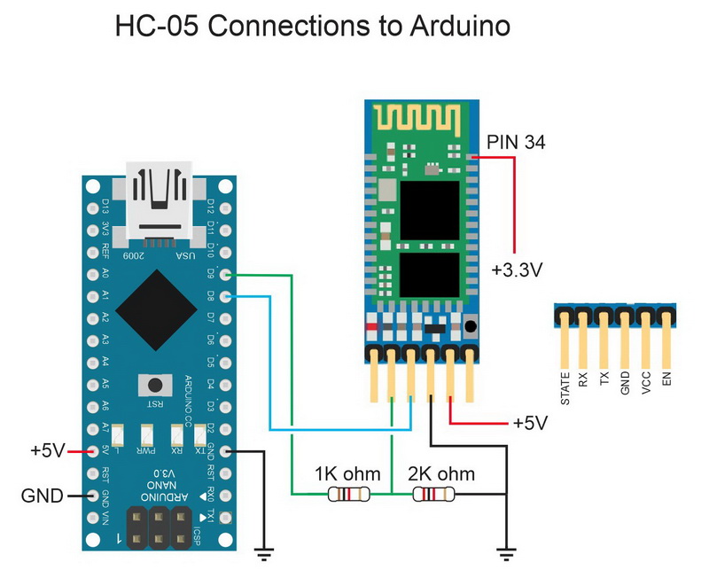
HC-05 with 2.0-20100601: Connecting to an Arduino
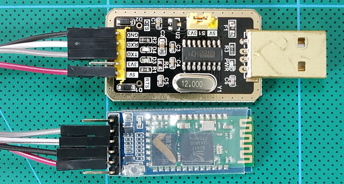
To use AT commands we need to communicate with the HC-05 over the serial UART channel. There are 2 main ways of doing this; with a USB to serial UART adapter, or an Arduino and a serial in – serial out sketch.
If using a serial UART adapter simply connect and open the Arduino serial monitor. Be aware that the main window will only display the replies from the HC-05.
The HC-05 RX pin is 3.3v not 5V. The adapter here has a jumper to select the voltage. If your adapter is 5V only you will need to bring the adapters 5v TX line down to 3.3v before connecting to the HC-05s 3.3v RX pin.
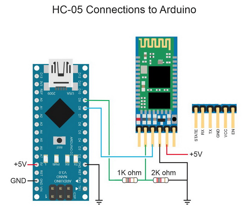
For the examples below I am using an Arduino and a serial sketch. Using this setup allows me to echo the commands to the serial monitor so we can clearly see what is happening.
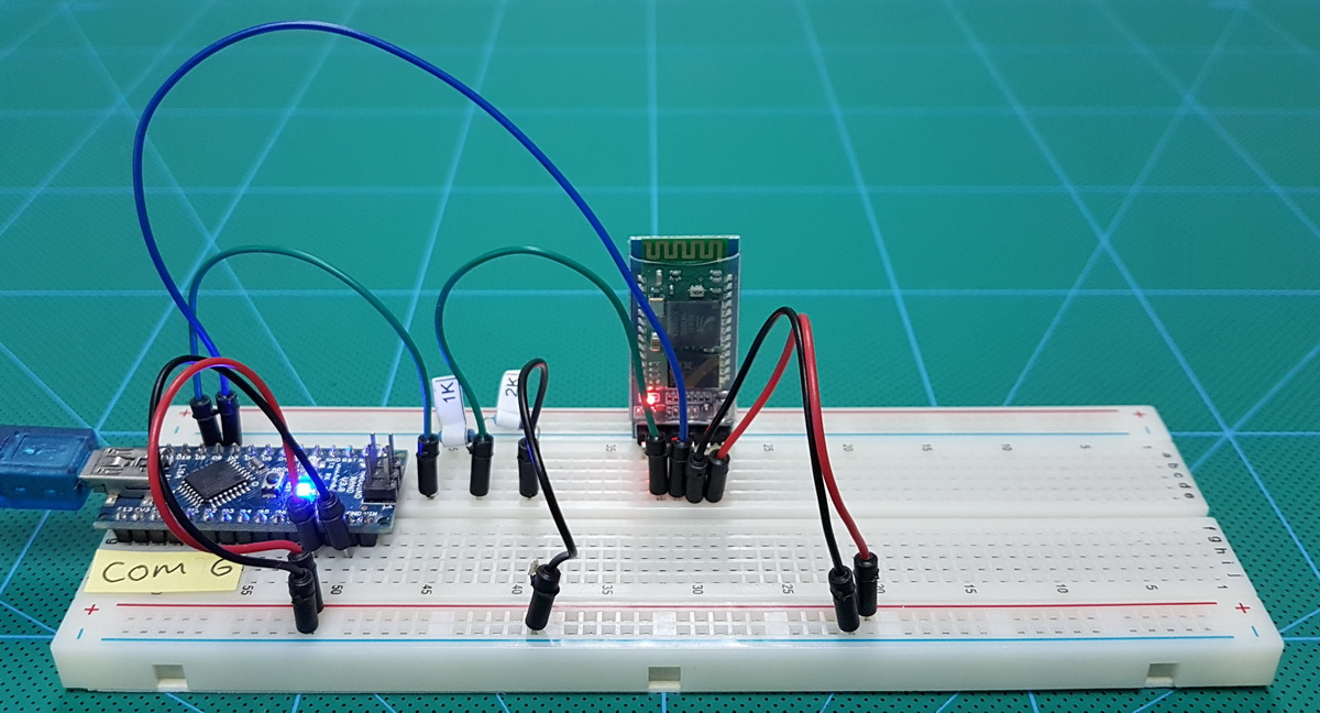
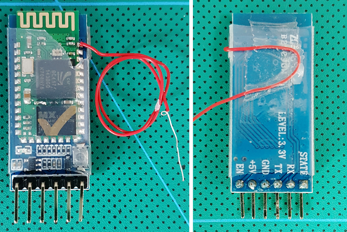
For convenience I have soldered a wire directly to pin 34. There is no need to do this unless you are using AT command mode a lot. If you just want to set up the HC-05 once or twice use the push button switch.
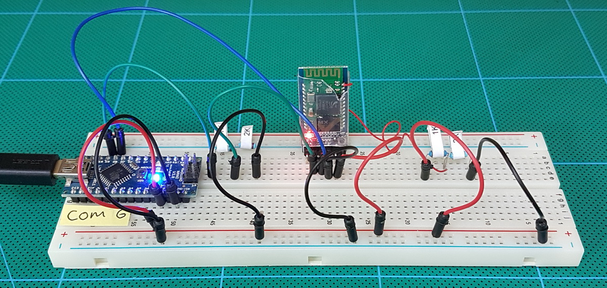
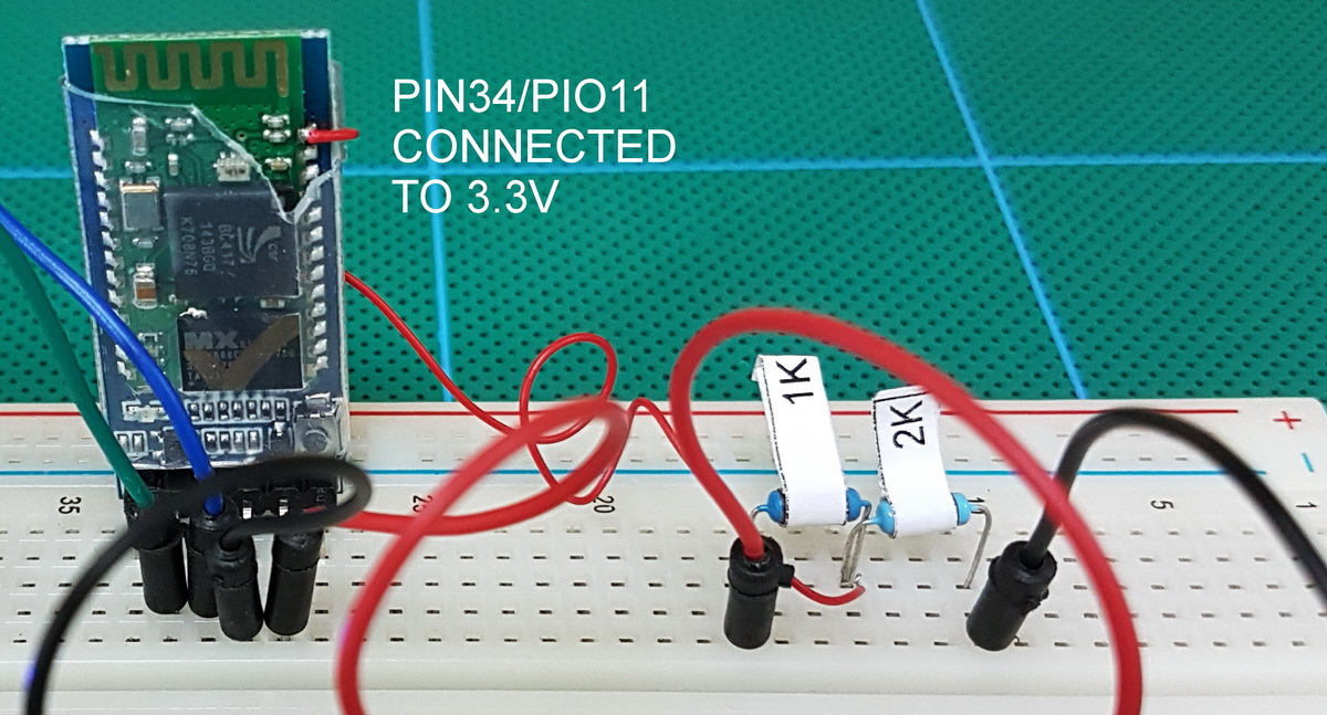 The voltage divider converts 5V to 3.3v. To control the pin status I use the main vcc lead to the voltage divider. To set pin34 to ground I simply remove the lead from 5v.
HC-05 with 2.0-20100601: Serial Sketch
// SerialIn_SerialOut_004 // // Uses hardware serial to talk to the host computer and Software Serial for communication with the bluetooth module // // What ever is entered in the serial monitor is sent to the connected device // Anything received from the connected device is copied to the serial monitor // // Pins // BT VCC to Arduino 5V out. // BT GND to GND // Arduino D8 (SS RX) - BT TX no need voltage divider // Arduino D9 (SS TX) - BT RX through a voltage divider (5v to 3.3v) // #include <SoftwareSerial.h> SoftwareSerial BTserial(8, 9); // RX, TX char c=' '; boolean NL = true; void setup() { Serial.begin(9600); Serial.print("Sketch: "); Serial.println(__FILE__); Serial.print("Uploaded: "); Serial.println(__DATE__); Serial.println(" "); BTserial.begin(38400); Serial.println("BTserial started at 38400"); Serial.println(" "); } void loop() { // Read from the Bluetooth module and send to the Arduino Serial Monitor if (BTserial.available()) { c = BTserial.read(); Serial.write(c); } // Read from the Serial Monitor and send to the Bluetooth module if (Serial.available()) { c = Serial.read(); BTserial.write(c); // Echo the user input to the main window. The ">" character indicates the user entered text. if (NL) { Serial.print(">"); NL = false; } Serial.write(c); if (c==10) { NL = true; } } } |
HC-05 with 2.0-20100601: Initial Communications Test
To check that everything is wired up correctly we can use the “AT” command. This simply returns an “OK”.
Make the circuit, connect to the Arduino. The LED on the HC-05 should be blinking quickly about 5 times a second. When the HC-05 is in AT command mode the LED will change to slow blink, 2 seconds on, 2 seconds off.
Enter AT command mode using the push button switch
– remove the power to the HC-05
– press and hold the button switch
– add power to the HC-05 (while holding the button switch)
– when you see the LED come on release the button switch.
Enter AT command mode using a direct connection to pin 34
If you had pin 34 connected to 3.3v the HC-05 should have started in AT command mode. If it did not:
– remove power
– connect pin34 to +3.3v
– add power
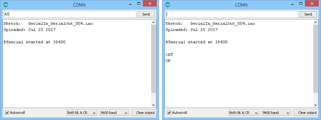
Open up the Arduino IDE and upload the above sketch. Then open the serial monitor. You see something like:
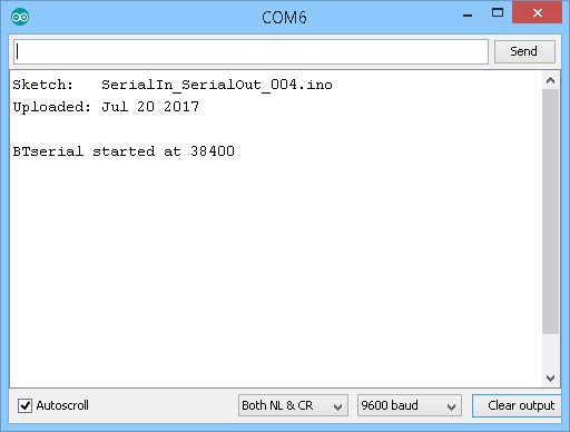
Make sure “Both NL &CR” is selected and the baud rate is set to 9600.
Note that there are 2 different baud rates being used; 9600 for the serial monitor, and 38400 for the HC-05.
To see if we have everything connected correctly, enter “AT” and you should get an “OK” reply.
HC-05 with 2.0-20100601: Main AT Commands
The 2.0-20100601 firmware has a fairly long list of commands. Some perform common functions and others you may never need. Here are some of the more useful/common commands. Remember that some commands need pin 34 to be HIGH. I have tried to highlight this but may have missed some. If you are using the button switch and do not get a reply, try closing the switch and send the command again (while keeping the switch closed).
| Command | Comment |
| AT | Serial communications test. Returns “OK”. |
| AT+VERSION? | Get the firmware ID/version number. Returns “+VERSION:2.0-20100601”. |
| AT+ORGL | Resets the module to the factory default settings. Returns “OK”. |
| AT+RESET | Restarts the module. Some times required for changes to take place. |
| AT+NAME? | Get the device name. Requires pin 34 to be HIGH. If the pin is not HIGH the HC-05 will not reply. Returns the device name such as “+NAME:H-C-2010-06-01”. |
| AT+NAME=newName | Change the modules name to newName. Returns an “OK” if successful. |
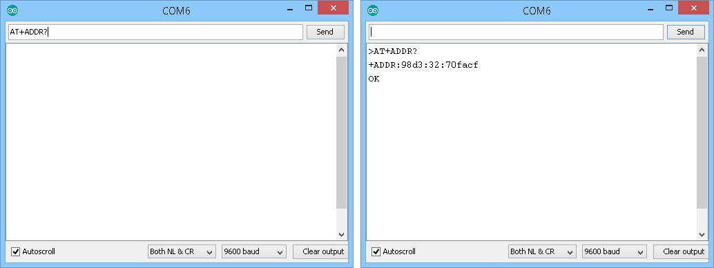
| AT+ADDR? | Query the module mac address. Returns a hex value in the form “+ADDR:1234:12:123456”. |
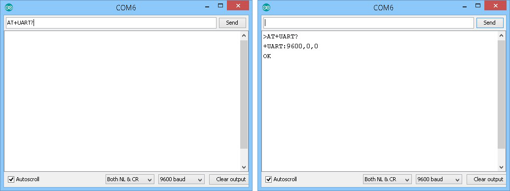
| AT+UART? | Query the baud rate used for UART serial communication. This is the speed a host device like an Arduino uses to talk to the BT module. It is not the the speed used to send wireless signals between different modules. Returns the baud rate, stop bit, parity bit in the form “+UART:38400,0,0” |
| AT+UART=baudRate,stop,parity | Set the baud rate used for serial UART commincation. baudRate is one of the following decimal values: 4800 9600 19200 38400 57600 115200 230400 460800 1382400 stop is the stop bit. Either 0 or 1 parity is the parity but. Either 0, 1, or 2. 0 = none. 1 = odd. 2 = even. i.e. “AT+UART=38400,0,0” |
| AT+STATE? |
Query the current device state. Replies with one of the following: INITIALIZED READY PAIRABLE PAIRED INQUIRING CONNECTING CONNECTED DISCONNECTED UNKNOWN |
| AT+ROLE? | Query the current role. Returns 0,1, or 2. 0 = slave mode 1 = master mode 2 = slave echo mode. |
| AT+ROLE=x |
Set the module mode. Where x = 0,1, or 2. AT+ROLE=0 puts the HC-05 in to slave mode. AT+ROLE=1 puts it in to master mode. AT+ROLE=2 puts it in to slave echo mode. Returns “OK” if successful. In Slave echo mode, the module echos back the data it receives. |
| AT+CMODE? | Query the current connection mode. Returns the connection mode value (0,1,2) in the form “+CMOD:0”. 0 = Manual connection. 1 = Auto connection on start. 2 = Slave loop mode. |
| AT+CMODE=x |
Set the connection mode. Where x can be 0,1, or 2. For CMODE to work, the module has to be in master mode (“AT+ROLE=1”). 0 = Manual connection: The remote device address must be specified to make a connection. 1 = Auto connect: Connect to any module/last connected module on start. 2 = Slave loop mode. |
| AT+PSWD? | Query the current PIN. Returns a 4 digit decimal number. |
| AT+PSWD=xxxx | Set the PIN code used for pairing xxxx = a 4 digit decimal number. |
| AT+PAIR=address,timeout | Attempt to PAIR with a remote Bluetooth device. The address must be in the form 1234,56,abcedef (notice the commas). timeout is a decimal value that sets the length of time to try. “AT+PAIR=98d3,32,70facf, 9″ attempts to PAIR with a slave module with the address 98d3:32:70facf for 9 seconds. If pairing is not successful within 9 seconds a”FAIL” error message is given. The SPP has to be initialized before using the AT+PAIR command. |
| AT+INIT | Initialize the Serial Port Profile (SPP) This is required by some of the other commands. “AT+INIT” requires pin34 to be HIGH. If the HC-05 is in AT command mode but pin34 is not HIGH the module will not reply. If AT+INIT is used and SPP has already been initialized the “ERROR(17)” error message is given. If a command requires SPP and it has not been initialized a “ERROR(16)” error message is given. |
For a full list of the available commands, download the datasheet.
AT+NAME
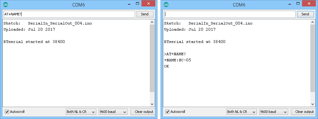
To get the modules name, use “AT+NAME?”
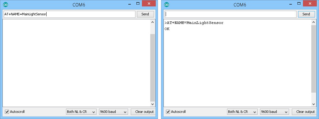
To change the name of the module use “AT+NAME=newName” where newName is any string up to 32 characters in length. To change the name to “MainLightSensor” use “AT+NAME=MainLightSensor”
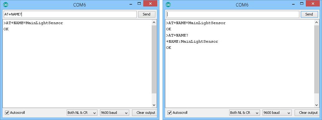
And use “AT+NAME?” again to check the change was successful.
Note:
“AT+NAME?” only works when pin 34 is HIGH, therefore, if using the button switch you need to press and hold the switch closed while you send the command. After you get a reply you can release the switch.
“AT+NAME=newName” works when pin 34 is HIGH or LOW (as long as you are in AT command mode of course).
AT+ADDR
To get the mac address of the HC-05 use “AT+ADDR?”. This is a read only command and you cannot change the mac address.
AT+UART
To get the baud rate used for serial commication when in transmission mode use “AT+UART?”.
To set the baud rate use “AT+UART=baudRate,stop,parity” where baudRate is one of the values from the list in the table above. For most occasions stop and parity should be 0. To set the baud rate to 57600 the command is “AT+UART=57600,0,0″
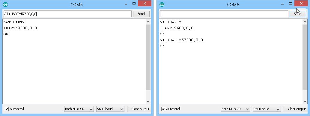
Remember, this sets the baud rate for the transmission mode only. The baud rate for AT command mode is set to 38400.
Note:
Software serial doesn’t work well at high speeds. The fastest I have good results with is 38400 and this is not 100% guaranteed. If speed is important but not critical try AltSoftSerial. If speed is critical you really need to be using the hardware serial channel.
In all the examples I use Software serial or AltSoftSerial to talk to the Bluetooth module. This leaves the hardware serial free so I can use the serial monitor.
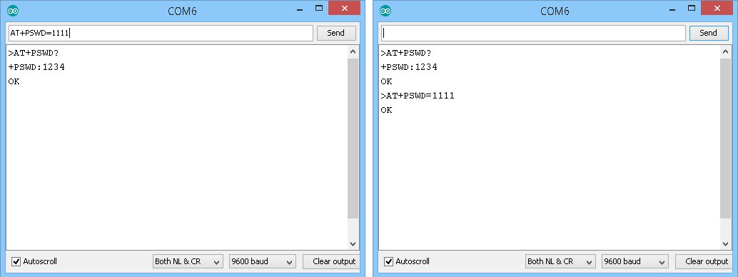
AT+PSWD
Bluetooth 2 devices often require a PIN or passcode when pairing with other devices.The HC-05 is no exception and to see what the PIN is set to use “AT+PSWD?”
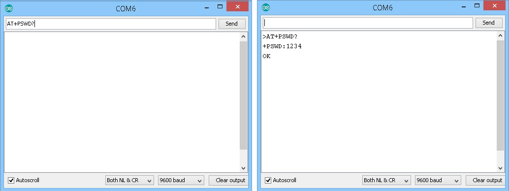
and to set a new PIN use “AT+PSWD=xxxx” where xxxx is a 4 digit number.
HC-05 with 2.0-20100601: AT Commands Dealing With Connections
Not yet available. In the meantime please see the links below.
HC-05 with 2.0-20100601: Making A Connection
Connecting 2 Arduinos by Bluetooth using a HC-05 and a HC-06: Easy Method Using CMODE
Connecting 2 Arduinos by Bluetooth using a HC-05 and a HC-06: Pair, Bind, and Link
HC-05 with 2.0-20100601: Downloads
HC-05 FW 2.0-20100601 DataSheet (English)
After trying several suggestions to configure HC-05 through arduiino, I use an USB-TTL to enter AT Mode and change the name for bluetooth. After that I realize that arduino can be configured as USB-TTL. Why suggest to use a sketch when Arduino can work as USB-TTL directly?
https://twitter.com/albfanjul/status/924570591717396480
I draw it into a fritzing schematic, you can reuse here if you want, don’t know exactly how to license it for that but it is mean to be free for reuse
I try this program in my Bluetooth modual and its works very well but there is one problem when i tried to do the same on my another bluetooth modual with version 3.0 some at commnands doesn’t work link “AT+INIT” , AT+INQ” soo what can i do for this ??? is there any method to change the frimware version of bluetooth modual?
Unfortunately I have not come across modules with the newer firmware yet.
I have recently purchased 3 sets of modules that were supposed to have the new firmware but all came with version 2. I decided to wait awhile before trying again.
Martyn,
I have just received HC-05 modules version “4.0-20190815”. email me if you want any further info.
Please, send me further info to me email.
Hi,
I am trying to Change Password/Pin of Module 4.0-20190805. I have tried all methods to enter AT Mode like ( Pin 34 to 3.3v, Key Pin to 5.0v, Button Press while connecting to Power). I can change the name of device but Can’t change the Password/Pin. During the session it shows the changed Password/Pin but on session end it keeps the new name but not new Password/Pin. I have many modules and all does the same. Can you help me with it.
Hello
I have the same problem, did you not find a solution?
First change password, then change name, ok
We got HC05 ver04, its AT commands are working well, but the data transfer between our device(slave) and android mobile(master) is not properly working, but with HC05 V2.0 , there is no any issue in communication between our device and mobile.
Any changes in HC05 Ver 04, Can you help us ?
You da real MVP! Thanks for this compilation, it helped me a lot!
Hi, how to change databits 8 to 7?
hi Martyn = this is cool. But I am stuck. I can’t seem to get to what you call “Full At” mode.
Specifically trying to get command “AT+INQ” to work but failing.
version +VERSION:hc01.comV2.1
1. when I power on hold and hold in the ‘small button switch which connects pin 34’ it enter some partial AT mode
2. i can set ROLE, see CMODE, STATE
3. but two commands don’t work: NAME and INQ (with ROLE=1 and CMOD=1)
4. if i again hold button and enter commands then NAME works; but INQ still doesn’t (error 16)
5. Curiously, I (I think) am able to set PIN 11 to high (which is pin 34, I think) . I run “PIO=11,1” and then NAME works, but still INQ doesn’t work
6. so just wonder what you’d suggest? (Maybe I’ll get from different source)
NAME:HC-05
OK
+VERSION:hc01.comV2.1
OK
+STATE:INITIALIZED
OK
+CMOD:1
OK
+ROLE:1
OK
+MPIO:900
Hey Martyn – never mind,problem solved . (That one anyway). Hooking wire to pin 34 and allowed me to get Command mode and run AT+INQ.
Still it was interesting that I could get some more AT Commands (NAME, specifically) by run setting Pin 11 (which I think is Pin34) to high via AT+PIO command .
Thanks for posting back
Well now I have HC-05 from three different sellers.
For two of them >”AT+VERSION” gives:
+VERSION:2.0-20100601
With these two I do NOT need to push the button or put wire to PIN 34
A. First I RESET (I typed “AT+RESET”)
Then I Initialized. (I typed “AT+INIT”)
I set ROLE=1 (I typed “AT+ROLE=1”)
I set CLASS= 0 (I typed “AT+CLASS=0”)
i set CMODE=1 (I typed “AT+CMODE=1”)
I set the search parameters via AT+INQM
Then I ran AT+INQ. And it worked.
B After INQ was done, the HC05 was still flashing quickly.
at this point “AT+STATE” returned “+STATE:INQUIRING”
But then I ran “AT+RESET” and lashing slowed back to off/on every second or so.
(and AT+STATE returns “+STATE:INITIALIZING”)
and then I run “AT+INIT”
and then I could run AT+INQ again
one correction/addition to above: while I didn’t run a wire to pin 34 or hold the button – I did put 3.3v to the EN pin on the board (hoping that would raise the internal power to high). Sorry I left that out.
An additional ‘bug’ that I overcame. Originally when I ran AT+INQ successfully I would get bad numbers for RSSI (signal strength). The RSSIs would all read “7FFF ” no matter where I moved devices.
So this version AT+INQM command isn’t quite working properly – on first run it doesn’t really read the 1 in
“>at+inqm = 1,9,9”
BUT I (finally) got it to work by
(a) first running “>at+inqm = 0,9,9” and THEN
(b) running “>at+inqm = 1,9,9”
(I guess some related buffer wasn’t really cleared until you actually set the RSSI parameter to 0).
But then it works.
Sorry to go on about this – but I had searched many, many things for info and yours has been the clearest. Thanks again
I’m trying to put mt HC05 into AT command mode and I can’t get the slow flash. I have tried holding down the button on the HC05, and also soldered a wire to pin 34. Either way, the LED won’t go into the slow flash mode. It comes on, stays on for a little less than a second, off for same amount of time, etc. I have the TX on the HC05 connected to TX on my Nano, RX to RX using a voltage divider, 5v to the VCC andto the EN output of the HC05 and of course the ground to ground. I loaded your sample sketch to my Arduino. Going into the serial monitor I set it to both NL and CR, set the baud to 9600. The intro displays with the path that the sketch is saved to, it shows the BT serial is 38400, and gives me the cursor. I type AT and nothing happens.
I have tried everything I can think of and can’t get the AT mode. If I power up the HC05 without pushing the button, the flash rate doesn’t change. I bought the HC05 from ebay, it’s probably a Chinese knockoff. Do I need to update the firmware? Thank you very much for your help, I am at a dead end.
Hello,
I thank you for the very comprehensive tutorials whose helped me to develop my first applications; I’m particularly interested in the wireless commections via BT.
My current project would require a bi-directionnal transmission between two sets of Nano+HC05; I already managed to get a one direction connection (master to slave) but what I need now is to get an aknowledgment of receipt of some orders from the slave part; Before going further in trials, I’m solliciting your advice to know if it is feasible with such configuration or if not, if there is any other configuration suitable for such task; Thanks.
When 2 HC-05s are connected the communication is bidirectional and each Arduino can be either the master or the slave or equal nodes. The connections are the same for both Arduinos.
RE acknowledgement.
There are different ways of doing this. My usual method is
Arduino 1 send the original message & start a timer.
Arduino 2 gets message
Arduino 2 returns a received message
Arduino 1 receives the return message and stops the timer. Everything is OK.
Arduino 1 If the timer reaches a time out period (say 1 second) show an error in some way.
Thanks a lot Martyn; very impressed by your reactivity!
I just set the role = 2 slave loop (AT+ROLE=2) accidental and I cant seem to change that role! Every thing I send is just echoed back into the serial monitor, even AT+RESET and AT+ORGL, please help!
without knowing exactly which module you have (there are many different ones) all I can suggest is you bring pin 34 HIGH on power on. This should put the module in to AT Command mode at UART 38400. You should then be able to change the settings.
hola muchas gracias me sirvio tu tutoria fanstastico pude resolver ese enigma mi HC05 solo tenia 4 pines y pense que era el HC06 pero soldando el pin34 pude entrar en modo AT y cambiar las configuraciones.
saludos desde Ecuador
sorry dont speaking English. but read fine
Martyn excellent article … I have 5 x HC05s with 3 different Version numbers as follows:
1 of hc01.comV2.1
2 of 2.0-2010 0601
and 2 new FC05 off ebay this month being both version 4.0-20190815
QUESTION… Is there any benefit in upgrading the the older software versions or could there be any hardware restrictions with the older HC05?
If upgradable where is the new firmware available from ??
This is very useful. I can solve my problem from this. Thank you. Please excuse for my bad english
Thanks for posting the information. I used your information to change the settings on a XBEE Bluetooth B2.0 version module with an Arduino XBEE shield. I removed the processor from the Arduino Uno 3 and used Arduino IDE to connect to the XBEE module. I used the IDE serial monitor to type in the AP commands. I used the baud settings in your post. I connected pins 1 and 20 with a wire with alligator clips to put the XBEE Bluetooth module into full AP command mode. This worked with the inexpensive ($6.99) Fundruino (Red/white) XBEE Bluetooth module and the more expensive Keystudio (Black/yellow) XBEE Bluetooth module. Hope this helps someone else, caused I was frustrated till I read your post.
I should have stated that I am using the HC-05 version of the XBEE Bluetooth module and Version 3.0 of the XBEE Shield. The connection to pins 1 and 20 must stay connected to remain in the full AP command mode. If 1 and 20 are briefly connected, the XBEE Bluetooth module enters the mini AP command mode and to out will not have full access to the AP commands.
Hi, I have two HC-05 modules from China, The radio chip on them is smaller than on your photos. Software version 2.0-20100601. I assume pin 34 is still on the same place of PCB?
My problem is that I cannot change ROLE to MASTER no matter what I do. First I tried with only EN pin high, then pressing and holding the button. After that I soldered wire to pin 34 and provided 3.3V, still it is impossible to change parameter ROLE. It is set to 0 and when i type AT+ROLE=1 it responds with OK, but parameter is not changed. I also tried to reset before and after this command.
Do you have any idea what could be wrong?
Hi Maksym i have the exact same issue as you have you figured it out?
Hi my HC05 module has this firmware and it will not go in Master mode i can enter AT+ROLE=1 command and says ok , but will not show as master , i have pin 34 held at 3.3v teh whole time
i do have this module on my own circuit board so i have connected all i think i need to connect but do you have a circuit diagram of breakout boards these come on as i am thinking i could be missing something as there is alot of resistors on these at the bottom where pins are
any help would be great
Thanks Martin