I am still very new to Visual Basic and I have been surprised at how quickly you can develop working apps. My first attempt resulted in a very basic app to receive data from the Arduino which taught me the basics of serial communication in VB. The next step is two way communication and controlling the Arduino from the VB program. I already have a similar project arduinoBTcontrol, where the Arduino is controlled from an Android app over Bluetooth. So all I need do is tweek the Arduino sketch and recreate the Android app in VB.
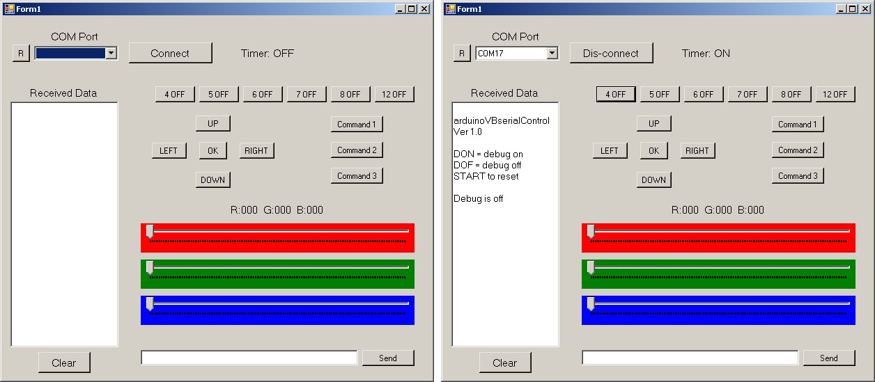
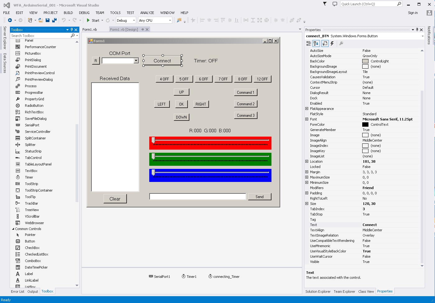
Here is the app screen.Visually it is nothing special and all controls are straight out of VB but is it working well.
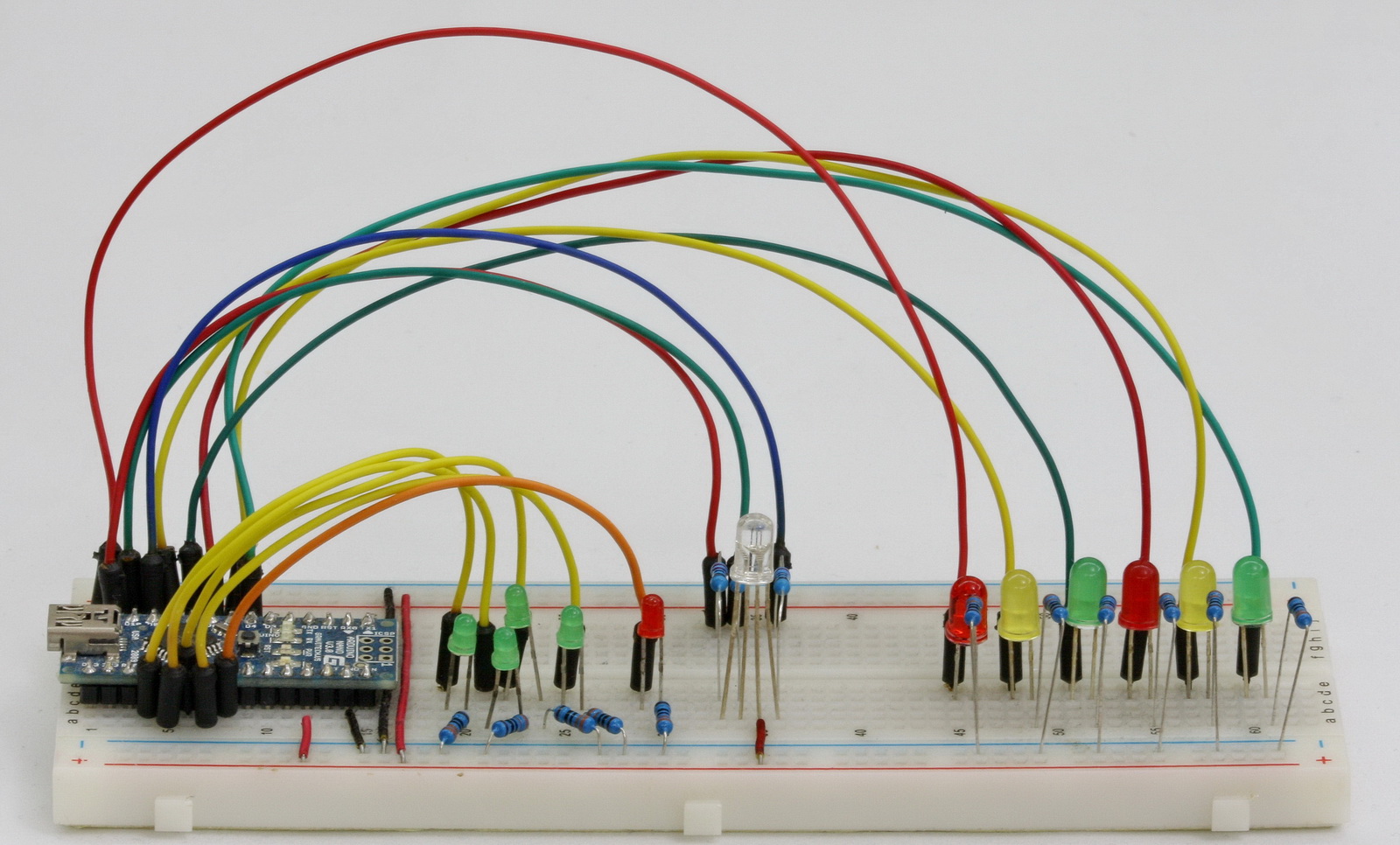
Here is the circuit. Basically the same circuit as used in the Bluetooth project minus the Bluetooth module.
Serial Communication
The communication between the Arduino and Visual Basic is done using ascii over serial/usb. The data sent to the Arduino is formatted in to commands which are enclosed in start and end markers; "<" and ">".
In this example there is very little data sent from the Arduino to the host computer and so I have not used start and end markers for the data send from the Arduino. For a more complex project I would enclose all data in markers as an easy way to ensure I receive a complete command.
The Commands
Depending on the button / slider used, the VB program sends different commands to the Arduino. I have tried to make the commands easy to read and this makes them longer than they need to be. For example, to turn on the LED connected to pin 4 the command is “<P004ON>”, this can be shortened to “<P41>” by using 1 to mean HIGH and 0 to mean LOW.
![]()
P – Pin HIGH/LOW.
– <P001ON>, Pin 001 on or Pin 1 HIGH
– <P001OF>, Pin 001 off or Pin1 1 LOW
The button toggles between ON and OFF. First click turns the LED on, the second click turns the LED off
The Arduino Sketch recognises Pin 4,5,6,7,8,9, and 12
N – Navigation
– <NUON>, U for UP. ON for HIGH
– <NUOF>, U for UP. OF for LOW
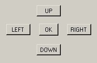
The navigation buttons work on button down and button up. When the button is clicked and the button becomes pressed the ON signal is sent. When the button is released the button returns to the up position the OF signal is sent.
There are 4 directions (up, down, left and right) and a OK/Select button
The OK button works with regular mouse clicks.
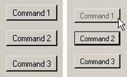
Command buttons.
There are 3 command buttons, these send the following commands
– <CMD01> – red / green flash
– <CMD02> – LED chaser
– <CMD03> – RGB LED cycle colours
The command buttons work in a different way to the other buttons. After a command is sent, the VB program waits for a completed signal from the Arduino. The clicked button becomes inactive until the completed signal is received.
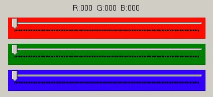
T – RGB slider
<Trrrgggbbb>
– rrr is the decimal value 0-255 for the red LED
– ggg is the decimal value 0-255 for the green LED
– bbb is the decimal value 0-255 for the blue LED
<T000000000> is fully off and <T255255255> is fully on
As soon as one of the RGB sliders is moved the new position is sent to the Arduino.
![]()
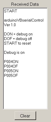
At the bottom of the window is a text box where any command can be entered by the user. The data entered is enclosed in the start and end markers before being sent to the Arduino.
The commands accepted are FON, FOF, DON, and DOF
– FON / FOF, acknowledgement on/of. If you turn this off the commands buttons never reset.
– DON / DOF, debug on/of. With debug on, the Arduino mirrors the data it receives back to the VB program. The commands are then displayed in the Received Data text box.
The Arduino Sketch
The Arduino sketch waits around for serial data and then depending on the data received does something. Basically turn an LED on or turn one off. Of course once you have the LEDs working you can change the sketch to do what ever you like.
The Arduino expects the data to be enclosed in start and end markers and anything received not contained in the markers is ignored.
Most of the work is done in the parseData() routine. This looks at the data received and reacts accordingly.
/* **************************************************** Sketch Arduino and Visual Basic Part 3 - Controlling an Arduino arduinoVBserialcontrol Arduino controlled by VisualBasic www.martyncurrey.com Some of the below code is not very elegant but it should be easy to see what is happening. Pins 2 3 4 LED 5 LED 6 LED 7 LED 8 LED 9 RGB LED RED PIN 10 RGB LED GREEN PIN 11 RGB LED BLUE PIN 12 LED 14 LED - LEFT 15 LED - DOWN 16 LED - UP 17 LED - RIGHT 18 LED - OK Commands The expected commands are Pin HIGH / LOW <P001ON> - P001 = Pin 1. ON = HIGH <P001OF> - P001 = Pin 1. OF = LOW RGB LED / Slider <Trrrgggbbb> - T is the slider command. rrr is the decimal value 0-255 for the red LED ggg is the decimal value 0-255 for the green LED bbb is the decimal value 0-255 for the blue LED Navigation <NUON> - N = navigation. U for UP. ON for HIGH <NUOF> - N = navigation. U for UP. OF for LOW U = up. D = down. L = left. R = right. K = OK/select Commands <CMD01> - red / green flash <CMD02> - LED chaser <CMD03> - RGB LED cycle colours Other. <HELLO> <FON> <FOF> <DON> <DOF> */ /////////////////////////////////////////////////////// boolean debug = true; // length of command is 20 chrs // if you need longer commands then increase the size of numChars const byte numChars = 20; char receivedChars[numChars]; boolean newData = false; unsigned int red = 255; unsigned int green = 255; unsigned int blue = 255; byte UPpin = 16; byte DOWNpin = 15; byte LEFTpin = 14; byte RIGHTpin = 17; byte OKpin = 18; boolean feedback = true; void setup() { pinMode(12, OUTPUT); pinMode(8, OUTPUT); pinMode(7, OUTPUT); pinMode(6, OUTPUT); pinMode(5, OUTPUT); pinMode(4, OUTPUT); pinMode(11, OUTPUT); pinMode(10, OUTPUT); pinMode(9, OUTPUT); // Common anode RGB lED, 255 is off. // If using a common cathod RGB lED then remove the next 3 lines. analogWrite(9, red); analogWrite(10, green); analogWrite(11, blue); pinMode(14, OUTPUT); pinMode(15, OUTPUT); pinMode(16, OUTPUT); pinMode(17, OUTPUT); pinMode(18, OUTPUT); Serial.begin(9600); sendStartMessage(); } void loop() { if (Serial.available() > 0) { recvWithStartEndMarkers(); } if (newData) { parseData(); } } /********************* * sends a start up message over serial. * Assumes serial is connected * * Global: * debug * Local: * */ void sendStartMessage() { Serial.println(" "); Serial.println("arduinoVBserialControl Ver 1.0"); Serial.println(" "); Serial.println("DON = debug on"); Serial.println("DOF = debug off"); Serial.println("START to reset"); Serial.println(" "); if (debug) { Serial.println("Debug is on"); } else { Serial.println("Debug is off"); } Serial.println(" "); } /********************* * Checks receivedChars[] for commands * * Global: * receivedChars[] * newData; * * Local: * */ void parseData() { newData = false; if (debug) { Serial.println( receivedChars ); } // HELLO // If the Arduino receives "HELLO" it sends "HELLO" back // This is used by the VB program to show it is connected if (strcmp(receivedChars, "HELLO") == 0) { Serial.println("HELLO"); //Blink the LED on pin 13 to show "HELLO" was received digitalWrite(13,HIGH); delay(100); digitalWrite(13,LOW); } if (strcmp(receivedChars, "START") == 0) { sendStartMessage(); } // PIN // P001ON - P for pin. 001 is the button number. ON = on // P001OF - P for pin. 001 is the button number. OF = off if (receivedChars[0] == 'P' ) { int tmp = convertToNumber( 1 ); if ( receivedChars[4] == 'O' && receivedChars[5] == 'N' ) { digitalWrite(tmp,HIGH); } if ( receivedChars[4] == 'O' && receivedChars[5] == 'F' ) { digitalWrite(tmp,LOW); } } // PIN // RGB SLIDER // Trrrgggbbb if ( receivedChars[0] == 'T' ) { // For a common anode RGB LED take the value away from 255. // If using a common cathod RGB led then use: // red = convertToNumber( 1 ); // green = convertToNumber( 4 ); // blue = convertToNumber( 7 ); red = 255 - convertToNumber( 1 ); green = 255 - convertToNumber( 4 ); blue = 255 - convertToNumber( 7 ); analogWrite(9, red); analogWrite(10, green); analogWrite(11, blue); } // RGB SLIDER // NAVIGATION // NUON - N = navigation. U for UP. ON for on // NUOF - N = navigation. U for UP. OF for off if ( receivedChars[0] == 'N' ) { if ( receivedChars[1] == 'U' ) // UP { if ( receivedChars[2] == 'O' && receivedChars[3] == 'N' ) { digitalWrite(UPpin,HIGH); } if ( receivedChars[2] == 'O' && receivedChars[3] == 'F' ) { digitalWrite(UPpin,LOW); } } if ( receivedChars[1] == 'D' ) // UP { if ( receivedChars[2] == 'O' && receivedChars[3] == 'N' ) { digitalWrite(DOWNpin,HIGH); } if ( receivedChars[2] == 'O' && receivedChars[3] == 'F' ) { digitalWrite(DOWNpin,LOW); } } if ( receivedChars[1] == 'L' ) // UP { if ( receivedChars[2] == 'O' && receivedChars[3] == 'N' ) { digitalWrite(LEFTpin,HIGH); } if ( receivedChars[2] == 'O' && receivedChars[3] == 'F' ) { digitalWrite(LEFTpin,LOW); } } if ( receivedChars[1] == 'R' ) // UP { if ( receivedChars[2] == 'O' && receivedChars[3] == 'N' ) { digitalWrite(RIGHTpin,HIGH); } if ( receivedChars[2] == 'O' && receivedChars[3] == 'F' ) { digitalWrite(RIGHTpin,LOW); } } if ( receivedChars[1] == 'K' ) // UP { if ( receivedChars[2] == 'O' && receivedChars[3] == 'K' ) { digitalWrite(OKpin,HIGH); delay(75); digitalWrite(OKpin,LOW); } } } // NAVIGATION //COMMAND //CMD01 //CMD02 //CMD03 // do not really need 3 characters. A single "C" would do. if ( receivedChars[0] == 'C' && receivedChars[1] == 'M' && receivedChars[2] == 'D' ) { if ( receivedChars[4] == '1') { for ( byte Count = 1; Count <= 15; Count++) { digitalWrite(4,HIGH); delay(100); digitalWrite(4,LOW); digitalWrite(12,HIGH); delay(100); digitalWrite(12,LOW); } if (feedback) { sendOK(1); } } if ( receivedChars[4] == '2') { for ( byte Count = 1; Count <= 5; Count++) { digitalWrite(4,HIGH); delay(100); digitalWrite(4,LOW); digitalWrite(5,HIGH); delay(100); digitalWrite(5,LOW); digitalWrite(6,HIGH); delay(100); digitalWrite(6,LOW); digitalWrite(7,HIGH); delay(100); digitalWrite(7,LOW); digitalWrite(8,HIGH); delay(100); digitalWrite(8,LOW); digitalWrite(12,HIGH); delay(100); digitalWrite(12,LOW); } if (feedback) { sendOK(2); } } if ( receivedChars[4] == '3') { red = 255; green = 255; blue = 255; for(int red = 255; red >0; red--) { analogWrite(9, red); delay (5); } for(int red = 0; red < 256; red++) { analogWrite(9, red); delay (5); } for(int green = 255; green >0; green--) { analogWrite(10, green); delay (5); } for(int green = 0; green < 256; green++) { analogWrite(10, green); delay (5); } for(int blue = 255; blue >0; blue--) { analogWrite(11, blue); delay (5); } for(int blue = 0; blue < 256; blue++) { analogWrite(11, blue); delay (5); } if (feedback) { sendOK(3); } } } // COMMAND // Typed commands ------------------------------------------------------- if (strcmp(receivedChars, "DON") == 0) { if ( receivedChars[1] =='O' && receivedChars[2] =='F' ) { debug = false; Serial.println("Debug is off"); } } if (strcmp(receivedChars, "DOF") == 0) { if ( receivedChars[1] =='O' && receivedChars[2] =='F' ) { debug = false; Serial.println("Debug is off"); } } // ACKNOWLEDGMENT // FON // FOF if ( receivedChars[0] == 'F' ) { if ( receivedChars[1] =='O' && receivedChars[2] =='N' ) { feedback = true; } if ( receivedChars[1] =='O' && receivedChars[2] =='F' ) { feedback = false; } if (feedback) { Serial.println("acknowledgment is on"); } else { Serial.println("acknowledgment is off"); } } // FEEDBACK if ( receivedChars[0] == 'D' ) { if ( receivedChars[1] =='O' && receivedChars[2] =='N' ) { debug = true; Serial.println("Debug is on"); } if ( receivedChars[1] =='O' && receivedChars[2] =='F' ) { debug = false; Serial.println("Debug is off"); } } } /********************* * Takes seial input and looks for data between a start and end marker. * * Global: * Updates receivedChars[] with the received data * * Local: * */ void recvWithStartEndMarkers() { // function recvWithStartEndMarkers by Robin2 of the Arduino forums // See http://forum.arduino.cc/index.php?topic=288234.0 static boolean recvInProgress = false; static byte ndx = 0; char startMarker = '<'; char endMarker = '>'; char rc; if (Serial.available() > 0) { rc = Serial.read(); if (recvInProgress == true) { if (rc != endMarker) { receivedChars[ndx] = rc; ndx++; if (ndx >= numChars) { ndx = numChars - 1; } } else { receivedChars[ndx] = '\0'; // terminate the string recvInProgress = false; ndx = 0; newData = true; } } else if (rc == startMarker) { recvInProgress = true; } } } /********************* * converts 3 ascii characters to a numeric value * * Global: * Expects receivedChars[] to contain the ascii characters * * Local: * startPos is the position of the first character * * */ int convertToNumber( byte startPos) { unsigned int tmp = 0; tmp = (receivedChars[startPos]-48) * 100; tmp = tmp + (receivedChars[startPos+1]-48) * 10; tmp = tmp + receivedChars[startPos+2]-48; return tmp; } void sendOK(int val) { // The 3 command buttons wait for the OK signal Serial.print("OK");Serial.println(val); } |
The Visual Basic Program
The program is written in VB2013 which is part of the Visual Studio package. I am using Visual Studio 2013 Community which is a full development package and available for free for hobbyists, students and freelance developers. Visual Studio 2013 Community is available for download at https://www.visualstudio.com/en-us/products/visual-studio-community-vs.aspx.
The VB program waits for the user to press a button or move a slider and then sends the appropriate command to the Arduino
' arduinoVBserial ' Arduino and Visual Basic: Receiving Data From the Arduino ' A simple example of sending and receiving data to and from an Arduino ' Imports System Imports System.IO.Ports Public Class Form1 ' Global variables Dim comPORT As String Dim receivedData As String = "" Dim connected As Boolean = False Dim count = 0 ' When the program starts; make sure the timer is off (not really needed) and add the available COM ports to the COMport drop down list Private Sub Form1_Load(ByVal sender As System.Object, ByVal e As System.EventArgs) Handles MyBase.Load Timer1.Enabled = False populateCOMport() End Sub 'The refresh button updates the COMport list Private Sub refreshCOM_BTN_Click(sender As Object, e As EventArgs) Handles refreshCOM_CB_BTN.Click SerialPort1.Close() populateCOMport() End Sub Private Sub populateCOMport() comPORT = "" comPort_ComboBox.Items.Clear() For Each sp As String In My.Computer.Ports.SerialPortNames comPort_ComboBox.Items.Add(sp) Next End Sub Private Sub comPort_ComboBox_SelectedIndexChanged(sender As Object, e As EventArgs) Handles comPort_ComboBox.SelectedIndexChanged If (comPort_ComboBox.SelectedItem <> "") Then comPORT = comPort_ComboBox.SelectedItem End If End Sub ' When the Connect button is clicked; if a COM port has been selected, connect and send out a HELLO message. ' Then wait for the Arduino to respond with its own HELLO. ' When the HELLO is received we are connected; change the button text to Dis-connect. Private Sub connect_BTN_Click(sender As Object, e As EventArgs) Handles connect_BTN.Click comPORT = comPort_ComboBox.SelectedItem If (connect_BTN.Text = "Connect") Then If (comPORT <> "") Then SerialPort1.Close() SerialPort1.PortName = comPORT SerialPort1.BaudRate = 9600 SerialPort1.DataBits = 8 SerialPort1.Parity = Parity.None SerialPort1.StopBits = StopBits.One SerialPort1.Handshake = Handshake.None SerialPort1.Encoding = System.Text.Encoding.Default SerialPort1.ReadTimeout = 10000 SerialPort1.Open() 'See if the Arduino is there count = 0 SerialPort1.WriteLine("<HELLO>") connect_BTN.Text = "Connecting..." connecting_Timer.Enabled = True Else MsgBox("Select a COM port first") End If Else 'connect_BTN.Text = "Dis-connect" 'close the connection a reset the button and timer label Timer1.Enabled = False Timer_LBL.Text = "Timer: OFF" SerialPort1.Close() connected = False connect_BTN.Text = "Connect" populateCOMport() End If End Sub 'The connecting_Timer waits for the Arduino to say HELLO. ' If HELLO is not received in 2 seconds display an error message. ' The connecting_Timer is only used for connecting Private Sub connecting_Timer_Tick(sender As Object, e As EventArgs) Handles connecting_Timer.Tick connecting_Timer.Enabled = False count = count + 1 If (count <= 8) Then receivedData = receivedData & ReceiveSerialData() If (Microsoft.VisualBasic.Left(receivedData, 5) = "HELLO") Then 'if we get an HELLO from the Arduino then we are connected connected = True connect_BTN.Text = "Dis-connect" Timer1.Enabled = True Timer_LBL.Text = "Timer: ON" receivedData = ReceiveSerialData() receivedData = "" SerialPort1.WriteLine("<START>") Else 'start the timer again and keep waiting for a signal from the Arduino connecting_Timer.Enabled = True End If Else 'time out (8 * 250 = 2 seconds) RichTextBox1.Text &= vbCrLf & "ERROR" & vbCrLf & "Can not connect" & vbCrLf connect_BTN.Text = "Connect" populateCOMport() End If End Sub 'After a connection is made the main timer waits for data from the Arduino 'Only OK1, OK2 or OK3 is available. Private Sub Timer1_Tick(sender As Object, e As EventArgs) Handles Timer1.Tick receivedData = ReceiveSerialData() RichTextBox1.Text &= receivedData Dim tmp As String tmp = Microsoft.VisualBasic.Left(receivedData, 3) If (tmp = "OK1") Then cmd1_BTN.Enabled = True End If If (tmp = "OK2") Then cmd2_BTN.Enabled = True End If If (tmp = "OK3") Then cmd3_BTN.Enabled = True End If End Sub Function ReceiveSerialData() As String Dim Incoming As String Try Incoming = SerialPort1.ReadExisting() If Incoming Is Nothing Then Return "nothing" & vbCrLf Else Return Incoming End If Catch ex As TimeoutException Return "Error: Serial Port read timed out." End Try End Function 'Clear the RecievedData text box Private Sub clear_BTN_Click(sender As Object, e As EventArgs) Handles clear_BTN.Click RichTextBox1.Text = "" End Sub 'LED buttons ' This is a basic example and to keep the code simple each button has a separate function. The code could be reduced by using the sender object 'If the Arduino is not connected a nessage box display an error message Private Sub Pin4_BTN_Click(sender As Object, e As EventArgs) Handles Pin4_BTN.Click If (connected) Then If (Pin4_BTN.Text = "4 OFF") Then SerialPort1.WriteLine("<P004ON>") Pin4_BTN.Text = "4 ON" Else SerialPort1.WriteLine("<P004OF>") Pin4_BTN.Text = "4 OFF" End If Else MsgBox("Not connected") End If End Sub Private Sub Pin5_BTN_Click(sender As Object, e As EventArgs) Handles Pin5_BTN.Click If (connected) Then If (Pin5_BTN.Text = "5 OFF") Then SerialPort1.WriteLine("<P005ON>") Pin5_BTN.Text = "5 ON" Else SerialPort1.WriteLine("<P005OF>") Pin5_BTN.Text = "5 OFF" End If Else MsgBox("Not connected") End If End Sub Private Sub Pin6_BTN_Click(sender As Object, e As EventArgs) Handles Pin6_BTN.Click If (connected) Then If (Pin6_BTN.Text = "6 OFF") Then SerialPort1.WriteLine("<P006ON>") Pin6_BTN.Text = "6 ON" Else SerialPort1.WriteLine("<P006OF>") Pin6_BTN.Text = "6 OFF" End If Else MsgBox("Not connected") End If End Sub Private Sub Pin7_BTN_Click(sender As Object, e As EventArgs) Handles Pin7_BTN.Click If (connected) Then If (Pin7_BTN.Text = "7 OFF") Then SerialPort1.WriteLine("<P007ON>") Pin7_BTN.Text = "7 ON" Else SerialPort1.WriteLine("<P007OF>") Pin7_BTN.Text = "7 OFF" End If Else MsgBox("Not connected") End If End Sub Private Sub Pin8_BTN_Click(sender As Object, e As EventArgs) Handles Pin8_BTN.Click If (connected) Then If (Pin8_BTN.Text = "8 OFF") Then SerialPort1.WriteLine("<P008ON>") Pin8_BTN.Text = "8 ON" Else SerialPort1.WriteLine("<P008OF>") Pin8_BTN.Text = "8 OFF" End If Else MsgBox("Not connected") End If End Sub Private Sub Pin12_BTN_Click(sender As Object, e As EventArgs) Handles Pin12_BTN.Click If (connected) Then If (Pin12_BTN.Text = "12 OFF") Then SerialPort1.WriteLine("<P012ON>") Pin12_BTN.Text = "12 ON" Else SerialPort1.WriteLine("<P012OF>") Pin12_BTN.Text = "12 OFF" End If Else MsgBox("Not connected") End If End Sub 'Command buttons Private Sub cmd1_BTN_Click(sender As Object, e As EventArgs) Handles cmd1_BTN.Click If (connected) Then SerialPort1.WriteLine("<CMD01>") cmd1_BTN.Enabled = False End If End Sub Private Sub cmd2_BTN_Click(sender As Object, e As EventArgs) Handles cmd2_BTN.Click If (connected) Then SerialPort1.WriteLine("<CMD02>") cmd2_BTN.Enabled = False End If End Sub Private Sub cmd3_BTN_Click(sender As Object, e As EventArgs) Handles cmd3_BTN.Click If (connected) Then SerialPort1.WriteLine("<CMD03>") cmd3_BTN.Enabled = False End If End Sub 'RGB sliders Private Sub red_TrackBar_Scroll(sender As Object, e As EventArgs) Handles red_TrackBar.Scroll updateRGBlbl() End Sub Private Sub green_TrackBar_Scroll(sender As Object, e As EventArgs) Handles green_TrackBar.Scroll updateRGBlbl() End Sub Private Sub blue_TrackBar_Scroll(sender As Object, e As EventArgs) Handles blue_TrackBar.Scroll updateRGBlbl() End Sub Private Sub updateRGBlbl() slider_LBL.Text = "R:" & Format(red_TrackBar.Value, "000") & " G:" & Format(green_TrackBar.Value, "000") & " B:" & Format(blue_TrackBar.Value, "000") If (connected) Then Dim data As String data = "<T" & Format(red_TrackBar.Value, "000") & Format(green_TrackBar.Value, "000") & Format(blue_TrackBar.Value, "000") & ">" SerialPort1.WriteLine(data) End If End Sub 'Navigation buttons Private Sub up_BTN_MouseDown(sender As Object, e As MouseEventArgs) Handles up_BTN.MouseDown If (connected) Then SerialPort1.WriteLine("<NUON>") End If End Sub Private Sub up_BTN_MouseUp(sender As Object, e As MouseEventArgs) Handles up_BTN.MouseUp If (connected) Then SerialPort1.WriteLine("<NUOF>") End If End Sub Private Sub down_BTN_MouseDown(sender As Object, e As MouseEventArgs) Handles down_BTN.MouseDown If (connected) Then SerialPort1.WriteLine("<NDON>") End If End Sub Private Sub down_BTN_MouseUp(sender As Object, e As MouseEventArgs) Handles down_BTN.MouseUp If (connected) Then SerialPort1.WriteLine("<NDOF>") End If End Sub Private Sub left_BTN_MouseDown(sender As Object, e As MouseEventArgs) Handles left_BTN.MouseDown If (connected) Then SerialPort1.WriteLine("<NLON>") End If End Sub Private Sub left_BTN_MouseUp(sender As Object, e As MouseEventArgs) Handles left_BTN.MouseUp If (connected) Then SerialPort1.WriteLine("<NLOF>") End If End Sub Private Sub right_BTN_MouseDown(sender As Object, e As MouseEventArgs) Handles right_BTN.MouseDown If (connected) Then SerialPort1.WriteLine("<NRON>") End If End Sub Private Sub right_BTN_MouseUp(sender As Object, e As MouseEventArgs) Handles right_BTN.MouseUp If (connected) Then SerialPort1.WriteLine("<NROF>") End If End Sub 'The OK button acts as soon as the button is clicked. It does not wait for the user to release the button 'There is no of for the OK button Private Sub ok_BTN_MouseDown(sender As Object, e As MouseEventArgs) Handles ok_BTN.MouseDown If (connected) Then SerialPort1.WriteLine("<NKOK>") End If End Sub 'Add the start and end markers to the contents of the text box and then send to the Arduino. 'Does not clear the contents Private Sub send_BTN_Click(sender As Object, e As EventArgs) Handles send_BTN.Click If (connected) Then Dim tmp As String tmp = "<" & send_TB.Text & ">" SerialPort1.WriteLine(tmp) End If End Sub End Class |
Connecting
To connect to the Arduino selected the appropriate COM port and click the connect button. The VB program will make a connection and send a HELLO message to the Arduino. If the Arduino replies then we are connected and the button text changes. If no reply is received then an error message is displayed.
Next steps
– add different functions such as motor control or send sensor data from the Arduino to the VB program,
– add regular checks to see if the Arduino is connected
– reset the command buttons when acknowledgement is turned off
– reset the Arduino when disconnected
Download
Download the Arduino Sketch, the VB program(exe file) and the VB2013 project files
I was wondering how you might implement different functions with the command buttons, for instance if I have a function that flashes 2 different pins (i’d like to loop it until another command is received from interface) how could I go about assigning it to button, but still make the arduino listen for the next command?
You would need to use millis() to control when things happened. On the Arduino forum this is usually referred to “doing several things at once”. Start with the post at https://forum.arduino.cc/index.php?topic=223286.0
Hi Martin,
Your code is working as expected, I’m using Visual studio 2017 and I can say that I’ve understood your code.
What I do not understand is the following:
When I click to connect the VB app send “HELLO”, so Arduino receive “HELLO”, next, Arduino reply with “HELLO” so VB app receive it and the communication is estabilished, here all OK.
But… I tried to change the Arduino reply with “CIAOO”, I wil expect that the communication fails…. instead the communication is extabilished correctly.
In debug mode I see that the received string from Arduino contains “Hello + CIAOO”, so scanning for only first 5 chars VB app fiund always “HELLO” and “CIAOO” is ignored and the comm is extabilished.
Can you explain this strange behavior?
Thanks
carlo