04.03.2017 – Updated the app to version 3. See the changes log below for details.
 Bluetooth Control Panel is a Bluetooth control app that can be used with a range of different microprocessors such as the Arduino. It uses Bluetooth 2.1 SSP such as the very popular, and cheap, HC-05s and HC-06s. A BLE/Bluetooth 4 version may come later.
All the initialization is done on the microprocessor side. The microprocessor sends commands to set up the controls and once the controls are active data can be sent from the microprocessor to the app and vice versa.
The app is Android only and can be downloaded from Google Play.
or download the app directly. You will need to side load on to your Android device. The direct download is version 3.01. The AYT command is fixed. Download Bluetooth Control Panel.
The Controls
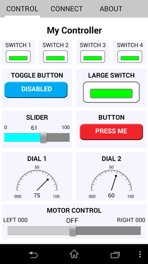
The control panel has a fixed layout. Across the top there are 4 small switches. Next there are the 4 main elements. Each of these can contain of of several different control types. Then there are 2 dials, 2 speed/direction controls and finally a text box. The elements are only visible after they have been initialized. This means you do not need to have unused controls on the screen.
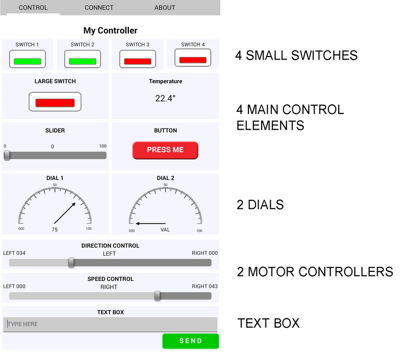
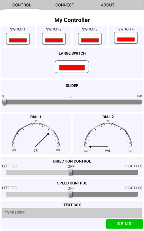 In the main grid, if only one control is initialized on a row the control will expand to fill the whole row.
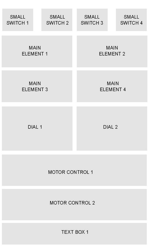 Each element within its group has a position number. The position is used in both the initialization command and the data command.
There are 10 kinds of control element:
– Small Switch
– Large Switch
– Value
– Button
– Toggle Button
– Slider
– Progress Bar
– Dial
– Speed/Direction slider
– Text Box
The elements in the main grid can contain any of the following controls:
– Large Switch
– Value
– Button
– Toggle Button
– Slider
– Progress Bar
Note that each position can contain only one control.
Small Switch
![]()
The Small Switch is a simple on/off switch. The switch state toggles when clicked; red to green to red.
There are 4 small switches across the top of the control panel.
The switch title can be set by the user.
The control background colour can be set by the user (optional).
Element position can be from 1 to 4.
| Initialization command: | <I,SS,element position,description(,colour)> <I,SS,1,LED 1,245245255> This initializes a small switch at position 1 with a title of LED 1 and a background colour of 245245255. |
| Data command sent to the microprocessor: | <SS[position][1/0]> <SS11> = Switch position 1, on <SS10> = Switch position 1, off |
| Data command from the microprocessor: |
<D,SS,[position],[1/0]> <D,SS,1,1> = Small switch in position 1, on <D,SS,1,0> = Small switch in position 1, off |
Large Switch
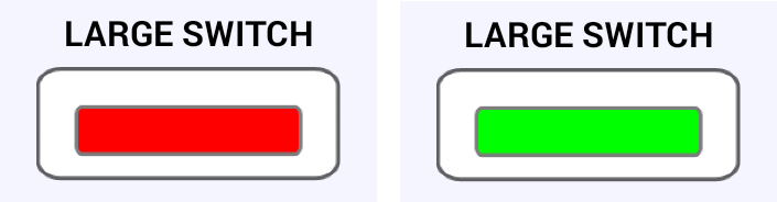
Similar to the small switch except bigger. The switch state toggles when clicked; red, green, red, etc.
There are 4 large switch control elements in the main grid, one in each position.
The element title can be set by the user.
The control background colour can be set by the user (optional).
Element position can be from 1 to 4.
| Initialization command: | <I,SW,element position,description(,colour)> <I,SW,1,Lights,245245255> Initializes the switch at position 1 with a title of Lights and a background colour of 245245255 (very pale blue) |
| Data command sent to the microprocessor: | <SW[position][1/0]> <SW11> = Switch 1, on <SW10> = Switch 1, off |
| Data command from the microprocessor: |
<D,SW,[position],[1/0]> <D,SW,1,1> = Switch in position 1, on <D,SW,1,0> = Switch in position 1, off |
Value
![]()
The Value control can display any alphanumeric value. The maximum length of the value depends on the device screen; small is 10 characters, large is 20 characters. Values longer than this will be truncated.
There are no checks for non printable characters and the app will try to display whatever you send to it.
The value control displays a value received from the microprocessor.
There are 4 value control elements in the main grid, one in each position.
The element title can be set by the user.
The control background colour can be set by the user (optional).
Element position can be from 1 to 4.
| Initialization command: | <I,VL,element number,description(,colour)> <I,VL,2,Temperature,245245245> Initializes the control at position 2 to a Value control with a title of Temperature and a background colour 245245245 (light grey) |
| Data command from the microprocessor: | <D,VL,element position,value > <D,VL,2,22.4°> = Value at position 2, display 22.4° |
Button

This is a regular button. The button sends commands to the microprocessor. It can not receive them.
There are 4 button control elements in the main grid, one in each position.
The element title can be set by the user.
The button text can be set by the user.
The control background colour can be set by the user (optional).
Element position can be from 1 to 4.
| Initialization command: | <I,BT,element position,description,button label text(,colour)> <I,BT,3,My Button,Press Me,255255128> Initializes a button control at position 3 with the title of My Button and a background colour 255255128 (yellow) |
| Data command sent to the microprocessor: | <BT[position]1> <BT31> = Button position 3 clicked |
Toggle Button
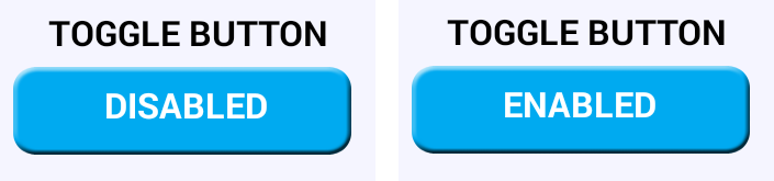
The Toggle Button is a 2 state button and the button labels toggle with each click, the button colour does not change. The button labels can be set by the user.
There are 4 toggle button control elements in the main grid, one in each position.
The element title can be set by the user.
The control background colour can be set by the user (optional).
Element position can be from 1 to 4.
| Initialization command: | <I,TB,element number,description,button label 1,button label 2(,colour)> <I,TB,1,My Button,Enabled,Disabled,255255128> Initializes the control at position 1 to a Toggle Button. The button text in state 1 to Enabled, the text in state 2 to Disabled and a background colour of 255255128 |
| Data command sent to the microprocessor: | <TB[position][1/0]> <TB20> = Button at position 2, state 1, <TB21> = Button at position 2, state 2 |
| Data command from the microprocessor: | <D,TB,[position],[1/0]> <D,TB,2,0> = Button in position 2, state 1, <D,TB,2,1> = Button state 2 |
Slider
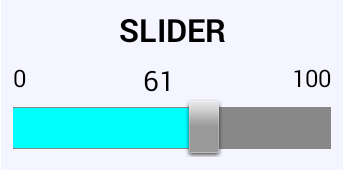
The Slider control is a standard slider. The user can set the minimum value (starting at 0) and the maximum value (up to 9999). Note, a slider with a large maximum value has a lower resolution and will increment in steps, for example a slider with a min of 1 and a max of 1024 increments in steps of 10 (0r 5 if using only one slider on the row). Due to this, setting the thumb position with data commands may not be exact.
There are 4 slider control elements in the main grid, one in each position.
The element title can be set by the user.
The control background colour can be set by the user (optional).
Element position can be from 1 to 4.
Sliders can send and receive data. The Sliders send data as soon as they are moved and this can cause a lot of commands being sent.
| Initialization command: | <I,SL,element number,description,min,max(,colour)> <I,SL,4,PWM,0,255,128255255> Initializes the control at position 4 to a Slider, the title is PWM. The minimum value is 0, maximum is 255 and background colour is 128255255 (light blue/aqua) |
| Data command from the microprocessor: | <D,SL,[element position],[value] > <D,SL,4,100> = Slider at element position 4, slider thumb position at 100. The maximum for the data value is 9999 unless a smaller value is set by the user. |
Data command sent from the app: | <SL[element position][value] > <SL40100> = Slider at element position 4, set the thumb position to 100. The data value is 4 digits. |
Progress Bar
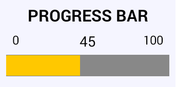
The progress bar is a standard progress bar. The user can set the minimum value (starting at 0) and the maximum value (up to 9999).
There are 4 progress bar control elements in the main grid, one in each position.
The element title can be set by the user.
The control background colour can be set by the user (optional).
Element position can be from 1 to 4.
Progress Bars can only receive data from the microprocessors, they cannot send.
| Initialization command: | <I,PB,element number,description,min,max(,colour)> <I,PB,2,Time Left,0,100,128255255> Initializes the control at position 2 to a Progress Bar, title is Time Left, Minimum value is 0, maximum value is 100 and the background colour is 128255255 |
| Data command from the microprocessor: | <D,PB,[element position],[value] > <D,PB,4,10> = Progress Bar at element position 4, set position to 10 |
Dial
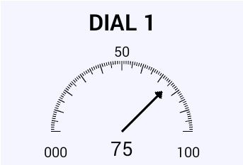
Directly under the main element grid there are 2 dials.
The user can set the minimum value (starting at 0) and the maximum value (up to 9999).
The element title can be set by the user.
The control background colour can be set by the user (optional).
Element position can be 1 to 2.
Dials can only receive data from the microprocessors, they cannot send.
| Initialization command: | <I,DI,element number,description,min,max(,colour)> <I,DI,1,Temperature,0,75,128255255> Initializes the Dial at position 1 with a title of Temperature. Minimum value of 0, maximum value of 75 and a background colour of 128255255 |
| Data command from the microprocessor: | <D,DI,[element position],[value] > <D,DI,1,25> = Dial 1, position 25 |
Note: Using dials can slow down the app, especially if there are several other controls in use or sending very frequent data.
2 Way Controller
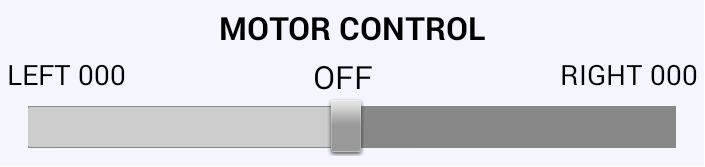
This control was designed to allow easy control over motors but can be used for other things too. It acts like a regular slider except the value goes from Left100 to Right100 rather than from 0 to 200. There is an OFF position at the centre. The values are fixed.
There are 2 motor controllers; 1 and 2.
The element title can be set by the user.
The control background colour can be set by the user (optional).
Element position can be 1 or 2.
Motor controllers can only send data to the microprocessors, they cannot receive. They start sending data as soon as they are moved and can generate a lot of data.
| Initialization command: | <I,MT,element number,description(,colour)> <I,MT,1,Direction,255255255> Initializes the 2 way controller at position 1 with a title of Direction and a background colour of 255255255 (white) |
| Data command to the microprocessor: | <DMT[element position][value]> <DMT1L025> = Motor controller 1, position left 25 |
Text Box
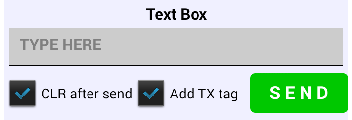
The text box allows the user to send any text they wish to the microprocessor. Text is entered in to the text box and sent when the SEND button is clicked. The text is wrapped in the < and > start and end markers.
The element title can be set by the user.
The background colour can be set by the user (optional).
Element position can only be 1.
When the CLR after send checkbox is checked the contents of the textbox will be cleared when the SEND button is clicked.
When Add TX tag is checked “TX1” is added to the start of the data before sending to the microprocessor.
Note that all data is contained within the start and end markers (< and >) tags whether or not the TX1 tag is included or not.
| Initialization command: | <I,TX,element number,description(,colour)> <I,TX,1,Text Box,255255255> Initializes the Text Box with a title of Text Box and a background colour of 255255255 |
| Data command to the microprocessor: Add TX tag checkbox ticked | <DTX[position][text]> <DTX1HELLO> – Text = “HELLO” |
| Data command to the microprocessor: Add TX tag checkbox not ticked | <[text]> <HELLO> – Text = “HELLO” |
Background Colours
The element background colours can be set by the user. This is optional and if not used the default light grey colour (235235235) will be used. The colour value is a 9 digit number in the form RRRGGGBBB. Each part (the RRR, GGG, or the BBB) can be a number from 000 to 255.
– White = 255255255
– Black – 000000000
– Blue = 000000255
– Red = 255000000
– Green = 000255000
An online color picker can be found at http://www.colorpicker.com/
Another useful colour tool is Colorhexa.
Other Initialization Commands
Title
| <T,main title> | Sets the main title for the control panel. The default is My Controller |
Refresh Rate
| <R,value> | Sets the app refresh rate. Must be a value from 1 to 10. 1 is fast, 10 is slow. 1 = 10ms. 10 = 100ms. The default is 2. |
EOI
| <EOI> | Tells the app to finish the initialization and display the controls. Should always be the final initialization command. |
Other Commands
Message
The Message command is used to create a pop up message box on the Android device. The command is sent from the microprocessor to the Android app.
The Message command can be used at any time; during initialization or as a data command. There are no checks and the app will try to display what ever you send to it.
| <M,message text> | Display a pop up message box in the app |
Connect
When the app establishes a connection it sends out a <CONNECT> message. The microprocessor can use this to confirm a connection is made before sending the initialization commands.
Reset
The app can be reset by either clicking the in app RESET button or by sending a RESET command from the microprocessor. In both cases the initialisation commands need to be resent.
When the RESET button in the app is clicked a <RESET> message is transmitted to the microprocessor.
| <RESET> | Remotely reset the app |
When the app receives a <RESET> command the app is returned to a non initialised state.
Disconnect
If the user closes the connection from the app the app sends a <DISCONNECT> message.
Are you there?
When using the basic HC-06 and HC-05s it is hard for the Arduino to know if the Bluetooth connection is actually active. One of the ways to confirm that there is an active connection is to receive data and this is where the Are You There, <AYT>, command comes in. When the app recieves the <AYT> command it replies with <YIA> (Yes I Am).
To check for an active connection keep sending the <AYT> command, once a second works well. If you get the reply then all is good. No reply and you know the connection has been lost.
If you want to do this through hardware use a HC-05 with a STATE pin. When a connection is established the STATE pin on the HC-05 goes HIGH. You can simply connect this to the Arduino and keep checking its state.
Examples
All the examples below are for the Arduino and use a regular HC-06 with a baud rate of 9600. Different baud rates can be used just match with the baud rate used to open the serial connection to the Bluetooth module in the Arduino sketch. The HC-05 can also be used in slave more.
All examples assume the Bluetooth module is already paired with the Android device.
Example 1a: Controlling an LED using a Small Switch
A basic example to get started with. In this example we use a small switch to control an LED. The control is one way, from the App to the Arduino and the Arduino simply reacts to commands it recieves.
The Arduino sketch sends the initialization commands as part of the setup function. This means if the app is reset the Arduino will also need to be reset and vice versa.
Circuit
The circuit has a HC-06 connected to pins D8 and D9 on the Arduino and an LED on pin D2 (plus suitable resistor). Here I am using a red LED and a 330 ohm resistor.
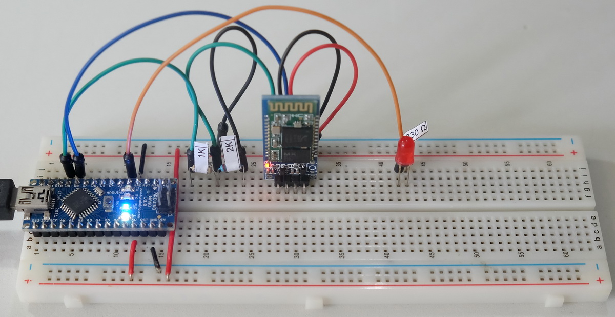
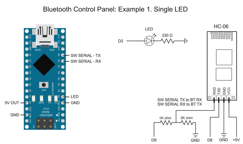
If you have any connection issues double check the connections.
Make sure the:
– Arduino RX goes to the BT TX
– Arduino TX goes to the BT RX via the voltage divider.
– resistors are the correct way around. The 1K resistor connects to the Arduino.
Using the App
Open the app
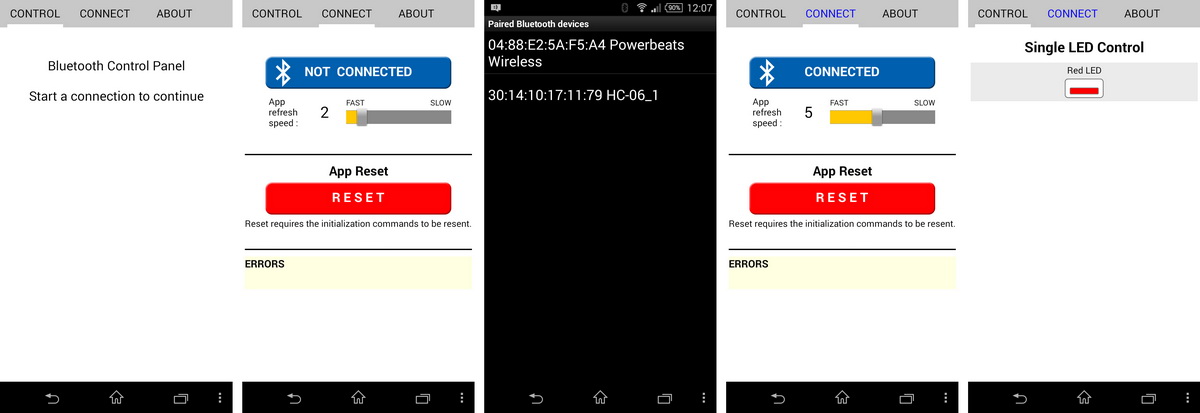
– The main page will be displayed asking you to start a connection.
– Go to the CONNECT page.
– Click the Bluetooth button. This currently says NOT CONNECTED.
– When you click the BT button a list of available Bluetooth devices is shown.
– Select the HC-06 (or which ever module you are using).
– The app will connect to the HC-06
– If the connection is successful the button will change to CONNECTED and the colour of the CONNECT tab will change to blue.
– If the initialization commands are received from the Arduino, the controls will be initialized and app will switch to the main page.
– The Arduino’s built in LED is used to show when the initialization commands have been sent.
Clicking the small switch will toggle from red to green and back. At the same time commands are sent to the Arduino to control the LED.
Arduino Sketch
The sketch is fairly simple. After the setup it waits for the CONNECT message. When it receives the message it sends the initialization commands. After this it repeatedly checks for incoming data and if it receives any it checks to see if the data is a command or not.
Main Parts
In the setup function the sketch waits for the CONNECT message. When it receives the message it sends the initialization commands.
// wait for CONNECT message boolean connected = false; while(!connected) { recvWithStartEndMarkers(); if (strcmp ("CONNECT",receivedChars) == 0) { connected = true; if (DEBUG) { Serial.println("Connected"); } } } |
After the CONNECT mesage is received the initialization commands are sent.
BTserial.print("<T,Single LED Control>"); // Control panel title BTserial.print("<I,SS,1,Red LED>"); // Initialize small switch 1. Switch description = Red LED BTserial.print("<R,5>"); // Set the app update speed to 50ms BTserial.print("<EOI>"); // End Of Initialization commands if (DEBUG) { Serial.println("Init commands sent"); } digitalWrite(13,HIGH); // Turn on the on board LED to show we are connected |
After this, the app simply keeps checking for incoming data and then processing any data it receives.
void loop() { recvWithStartEndMarkers(); // Check to see if we have received any new data if (newData) { processCommand(); } // if we have new data see if it is a command } |
The processCommand() function checks the received data. If it finds a command to turn on or turn off the LED it acts accordingly.
The two commands used are SS10 and SS11.
– SS10 is Small Switch 1, turn LED off
– SS11 is Small Switch 1, turn LED on.
void processCommand() { if (DEBUG) { Serial.print("receivedChars = "); Serial.println(receivedChars); } if (strcmp ("SS10",receivedChars) == 0) { digitalWrite(LED_RED_PIN,LOW); if (DEBUG) { Serial.println("LED LOW"); } } if (strcmp ("SS11",receivedChars) == 0) { digitalWrite(LED_RED_PIN,HIGH); if (DEBUG) { Serial.println("LED HIGH"); } } receivedChars[0] = '\0'; newData = false; } |
Full Arduino Sketch
/* * Sketch: BCP_Example_01a_Single_LED * By Martyn Currey * 17.07.2016 * Written in Arduino IDE 1.6.3 * * Requires the Bluetooth Control Pabrl Android App. Can be downloaded from Google Play. * See https://www.martyncurrey.com/bluetooth-control-panel * * Turn an LED on and off from an Android app * Uses the following pins * * D8 - AltsoftSerial RX * D9 - AltsoftSerial TX * D2 - LED * */ // AltSoftSerial uses D9 for TX and D8 for RX. While using AltSoftSerial D10 cannot be used for PWM. // Remember to use a voltage divider on the Arduino TX pin / Bluetooth RX pin // Download AltSoftSerial from https://www.pjrc.com/teensy/td_libs_AltSoftSerial.html #include <AltSoftSerial.h> AltSoftSerial BTserial; // Change DEBUG to true to output information to the serial monitor boolean DEBUG = true; // Variables used for incoming data const byte maxDataLength = 20; char receivedChars[21] ; boolean newData = false; // General variables const byte LED_RED_PIN = 2; void setup() { // Set the onboard LED pin for output pinMode(13, OUTPUT); digitalWrite(13,LOW); pinMode(LED_RED_PIN, OUTPUT); digitalWrite(LED_RED_PIN,LOW); if (DEBUG) { // open serial communication for debugging Serial.begin(9600); Serial.print("Sketch: "); Serial.println(__FILE__); Serial.print("Uploaded: "); Serial.println(__DATE__); Serial.println(" "); } // Open a software serial connection to the Bluetooth module. BTserial.begin(9600); if (DEBUG) { Serial.println("AltSoftSerial started at 9600"); Serial.println(" "); } newData = false; // wait for CONNECT message boolean connected = false; while(!connected) { recvWithStartEndMarkers(); if (strcmp ("CONNECT",receivedChars) == 0) { connected = true; if (DEBUG) { Serial.println("Connected"); } } } receivedChars[0] = '\0'; newData = false; BTserial.print("<T,Single LED Control>"); // Control panel title BTserial.print("<I,SS,1,Red LED>"); // Initialize small switch 1. Switch description = Red LED BTserial.print("<R,5>"); // Set the app update speed to 50ms BTserial.print("<EOI>"); // End Of Initialization commands if (DEBUG) { Serial.println("Init commands sent"); } digitalWrite(13,HIGH); // Turn on the on board LED to show we are connected delay(100); // Small delay to give the app time to set up. } // void setup() void loop() { recvWithStartEndMarkers(); // Check to see if we have received any new data if (newData) { processCommand(); } // if we have new data see if it is a command } /* **************************************** * Function processCommand * parses data commands contained in receivedChars[] * receivedChars[] has not been checked for errors * * passed: * * global: * receivedChars[] * newData * * Returns: * * Sets: * receivedChars[] * newData * */ void processCommand() { if (DEBUG) { Serial.print("receivedChars = "); Serial.println(receivedChars); } if (strcmp ("SS10",receivedChars) == 0) { digitalWrite(LED_RED_PIN,LOW); if (DEBUG) { Serial.println("LED LOW"); } } if (strcmp ("SS11",receivedChars) == 0) { digitalWrite(LED_RED_PIN,HIGH); if (DEBUG) { Serial.println("LED HIGH"); } } receivedChars[0] = '\0'; newData = false; } // function recvWithStartEndMarkers by Robin2 of the Arduino forums // See http://forum.arduino.cc/index.php?topic=288234.0 /* **************************************** * Function recvWithStartEndMarkers * reads serial data and returns the content between a start marker and a end marker. * * passed: * * global: * receivedChars[] * newData * * Returns: * * Sets: * newData * receivedChars * */ void recvWithStartEndMarkers() { static boolean recvInProgress = false; static byte ndx = 0; char startMarker = '<'; char endMarker = '>'; char rc; if (BTserial.available() > 0) { rc = BTserial.read(); if (recvInProgress == true) { if (rc != endMarker) { receivedChars[ndx] = rc; ndx++; if (ndx > maxDataLength) { ndx = maxDataLength; } } else { receivedChars[ndx] = '\0'; // terminate the string recvInProgress = false; ndx = 0; newData = true; } } else if (rc == startMarker) { recvInProgress = true; } } } |
Example 1b: Controlling an LED using a Small Switch. Sketch with initialized state and reset
This example keeps with the single LED but it expands the Arduino sketch and introduces a initialized state and the ability to reset the app and have the Arduino resend the initialization commands. Like the previous example control is one way; from the app to the Arduino. This sketch also flashes the built in LED to show that it is waiting for the CONNECT message.
The example uses exactly the same circuit as above but the sketch is different.
The initialization commands have been moved to their own function. We can call the function anytime we like and so send the initialization commands anytime we like.
void sendInitCommands() { BTserial.print("<T,Single LED Control>"); // Control panel title BTserial.print("<I,SS,1,Red LED>"); // Initialize small switch 1. Switch description = Red LED BTserial.print("<R,5>"); // Set the app update speed to 50ms BTserial.print("<EOI>"); // End Of Initialization commands delay(100); // Small delay to give the app time to set up. initialized = true; if (DEBUG) { Serial.println("Init commands sent"); } digitalWrite(13,HIGH); } |
A reset function has also been added. This simply ensures the LED is turned off when the reset command is received.
void reset() { digitalWrite(LED_RED_PIN,LOW); } |
The commands to turn the red LED on and off are the same but there are two new commands in the processCommand() CONNECT and RESET.
Rather than only checking for the CONNECT message in the setup function we are now checking in the main processCommand() function. This means we are always checking for it and the app can be restarted without having to restart the Arduino.
When the reset button in the app is clicked a RESET message is sent to the Arduino. This allows us to reset the initialization commands. In this example we are simply resending the same commands but you could send different commands if you so wished.
If you reset the Arduino you also need to click the RESET button in the app but you do not need to restart the app.
if (strcmp ("CONNECT",receivedChars) == 0) { sendInitCommands(); if (DEBUG) { Serial.println("CONNECT message received"); } } else if (strcmp ("RESET",receivedChars) == 0) { reset(); sendInitCommands(); if (DEBUG) { Serial.println("RESET received"); } } |
The main loop has been expanded and now uses the initialized variable. If initialized is false we flash the built in LED and check for new commands. When the CONNECT message is received initialized is set to true and the second part of the loop is performed.
The second part of the loop simply checks for incoming data and if it receives any it checks to see if the data is a command.
This example is fairly similar to the first one, we wait for the CONNECT message and then send the initialization commands. After this we wait for commands to turn the LED on and off. There is a subtle difference though. We are now waiting for the CONNECT message in the main loop and this, if we wished, allows us to do other things while waiting.
void loop() { if (!initialized) { // Flash the built in LED to show the Arduino is waiting for the initialization commands if ( millis()-flashStartTime > flashFreqTime ) { flashStartTime = millis(); if (digitalRead(13) == HIGH) {digitalWrite(13,LOW);} else {digitalWrite(13,HIGH);} } // Keep checking for the CONNECT message recvWithStartEndMarkers(); // check to see if we have received any new commands if (newData) { processCommand(); } // if we have a new command do something } if (initialized) { recvWithStartEndMarkers(); // check to see if we have received any new data if (newData) { processCommand(); } // if we have new data see if it is a command } // code can be inserted here to do anything you wish. This means the sketch can be doing stuff // even if the connection to the app is not established. } // void loop() |
Full Sketch
This all results in a larger sketch that does exactly the same as in the first example….However, it does it better. The sketch in this example can be scaled up much easier than the sketch in the first example and we can now reset the app without resetting the Arduino.
Another difference is in this sketch we are always checking the received data against all the commands and this could lead to issues if you are not careful but by using an initialized state we can decide what commands to process and when. For example, if not initialized and we receive a data command we can ignore it, or show an error in some way, or save it until later.
/* * Sketch: BCP_Example_01b_Single_LED_INIT_STATE * By Martyn Currey * 17.07.2016 * Written in Arduino IDE 1.6.3 * * Requires the Bluetooth Control Pabrl Android App. Can be downloaded from Google Play. * See https://www.martyncurrey.com/bluetooth-control-panel * * Turn an LED on and off from an Android app * Uses the following pins * * D8 - AltsoftSerial RX * D9 - AltsoftSerial TX * D2 - LED * */ // AltSoftSerial uses D9 for TX and D8 for RX. While using AltSoftSerial D10 cannot be used for PWM. // Remember to use a voltage divider on the Arduino TX pin / Bluetooth RX pin // Download from https://www.pjrc.com/teensy/td_libs_AltSoftSerial.html #include <AltSoftSerial.h> AltSoftSerial BTserial; // Change DEBUG to true to output debug information to the serial monitor boolean DEBUG = true; // Variables used for incoming data const byte maxDataLength = 20; char receivedChars[21] ; boolean newData = false; // Vaiables const byte LED_RED_PIN = 2; boolean initialized = false; unsigned long flashStartTime = 0; unsigned long flashFreqTime = 250; void setup() { // Set the onboard LED pin for output pinMode(13, OUTPUT); digitalWrite(13,LOW); pinMode(LED_RED_PIN, OUTPUT); digitalWrite(LED_RED_PIN,LOW); if (DEBUG) { // open serial communication for debugging Serial.begin(9600); Serial.print("Sketch: "); Serial.println(__FILE__); Serial.print("Uploaded: "); Serial.println(__DATE__); Serial.println(" "); } // open software serial connection to the Bluetooth module. BTserial.begin(9600); if (DEBUG) { Serial.println("AltSoftSerial started at 9600"); } newData = false; initialized = false; flashStartTime = millis(); } // void setup() void loop() { if (!initialized) { // Flash the built in LED to show the Arduino is waiting for the initialization commands if ( millis()-flashStartTime > flashFreqTime ) { flashStartTime = millis(); if (digitalRead(13) == HIGH) {digitalWrite(13,LOW);} else {digitalWrite(13,HIGH);} } // Keep checking for the CONNECT message recvWithStartEndMarkers(); // check to see if we have received any new commands if (newData) { processCommand(); } // if we have a new command do something } if (initialized) { recvWithStartEndMarkers(); // check to see if we have received any new data if (newData) { processCommand(); } // if we have new data see if it is a command } } // void loop() void sendInitCommands() { BTserial.print("<T,Single LED Control>"); // Control panel title BTserial.print("<I,SS,1,Red LED>"); // Initialize small switch 1. Switch description = Red LED BTserial.print("<R,5>"); // Set the app update speed to 50ms BTserial.print("<EOI>"); // End Of Initialization commands delay(100); // Small delay to give the app time to set up. initialized = true; digitalWrite(13,HIGH); if (DEBUG) { Serial.println("Init commands sent"); } } void reset() { digitalWrite(LED_RED_PIN,LOW); } /* **************************************** * Function processCommand * parses data commands contained in receivedChars[] * receivedChars[] has not been checked for errors * * passed: * * global: * receivedChars[] * newData * * Returns: * * Sets: * receivedChars[] * newData * */ void processCommand() { if (DEBUG) { Serial.print("receivedChars = "); Serial.println(receivedChars); } if (strcmp ("CONNECT",receivedChars) == 0) { sendInitCommands(); if (DEBUG) { Serial.println("CONNECT message received"); } } else if (strcmp ("RESET",receivedChars) == 0) { reset(); sendInitCommands(); if (DEBUG) { Serial.println("RESET received"); } } else if (strcmp ("SS10",receivedChars) == 0) { digitalWrite(LED_RED_PIN,LOW); if (DEBUG) { Serial.println("LED LOW"); } } else if (strcmp ("SS11",receivedChars) == 0) { digitalWrite(LED_RED_PIN,HIGH); if (DEBUG) { Serial.println("LED HIGH"); } } receivedChars[0] = '\0'; newData = false; } // function recvWithStartEndMarkers by Robin2 of the Arduino forums // See http://forum.arduino.cc/index.php?topic=288234.0 /* **************************************** * Function recvWithStartEndMarkers * reads serial data and returns the content between a start marker and an end marker. * * passed: * * global: * receivedChars[] * newData * * Returns: * * Sets: * newData * receivedChars * */ void recvWithStartEndMarkers() { static boolean recvInProgress = false; static byte ndx = 0; char startMarker = '<'; char endMarker = '>'; char rc; if (BTserial.available() > 0) { rc = BTserial.read(); if (recvInProgress == true) { if (rc != endMarker) { receivedChars[ndx] = rc; ndx++; if (ndx > maxDataLength) { ndx = maxDataLength; } } else { receivedChars[ndx] = '\0'; // terminate the string recvInProgress = false; ndx = 0; newData = true; } } else if (rc == startMarker) { recvInProgress = true; } } } |
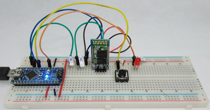
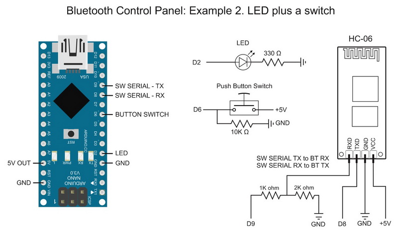
Example 2: Controlling an LED using a large switch in the app and a physical button switch on the microprocessor
Here we start sending data from the Arduino to the app. We are still using a single LED but now we are adding a physical button switch at the Arduino side. We can now use the button switch to control the LED from the local device. When the button switch is pressed commands are sent to set the button in the app to match the new state of the LED.
We are also changing the small switch in the app to a large switch.
The LED is still connected to D2 and the button switch has been added to D6.
Now that we have a physical button switch we need to check its status. In the main loop we call the checkSwitch() function.
if (initialized) { checkSwitch(); recvWithStartEndMarkers(); // check to see if we have received any new commands if (newData) { processCommand(); } // if we have a new command do something about it } |
The checkSwitch() function reads the state of the switch, works out if the switch has just been pressed and if the LED status needs to be changed. We keep track of the switch status and the LED status by using two variables; switchState and LED_RED_State.
Every time the button switch is pressed (the switch goes from LOW to HIGH) the LED state is changed. Either from off to on or from on to off. When using boolean variables, the statement
LED_RED_State = ! LED_RED_State; |
flips the value; either LOW to HIGH or HIGH to LOW and is the same as using
if (LED_RED_State == HIGH) { LED_RED_State == LOW; } else { LED_RED_State == HIGH; } |
void checkSwitch() { // Simple toggle switch function with very simple debouce. boolean state1 = digitalRead(SWITCH_PIN); boolean state2 = digitalRead(SWITCH_PIN); boolean state3 = digitalRead(SWITCH_PIN); if ((state1 == state2) && (state1==state3)) { switchState = state1; if ( (switchState == HIGH) && (oldSwitchState == LOW) ) { LED_RED_State = ! LED_RED_State; if ( LED_RED_State == HIGH) { BTserial.print("<D,SW,1,1>" ); digitalWrite(LED_RED_PIN,HIGH); if (DEBUG) { Serial.println("Sent - <D,SW,1,1>"); } } else { BTserial.print("<D,SW,1,0>"); digitalWrite(LED_RED_PIN,LOW); if (DEBUG) { Serial.println("Sent - <D,SW,1,0>"); } } } oldSwitchState = switchState; } } |
Because we introduced the initialized state we can now use the <RESET> command. However, we need to allow for the user resetting the app when the LED is on, therefore when the sketch receives the <RESET> command it calls the reset() function which in turn ensures the LED if off.
else if (strcmp ("RESET",receivedChars) == 0) { if (DEBUG) { Serial.println("RESET message received"); } reset(); sendInitCommands(); } |
void reset() { digitalWrite(LED_RED_PIN,LOW); } |
Since we have added the <RESET> command we might as well add the <DISCONNECT> command. If the user closes the Bluetooth connection from the app the app sends out the <DISCONNECT> command. This can be used to help allow the Arduino sketch to keep track of the connection status. In this example, when the command is received the sketch simply reverts to the non initialized state.
else if (strcmp ("DISCONNECT",receivedChars) == 0) { if (DEBUG) { Serial.println("DISCONNECT message received"); } reset(); initialized = false; } |
Download
Dowload the full sketch: BCP_Example_02_Large_Switch_LED_with_button_switch
Example 3: Displaying a temperature using a Value control
[Screen shots]
[breadboard photo]
[circuit diagram]
[Arduino sketch]
Example 4a: Control a Servo
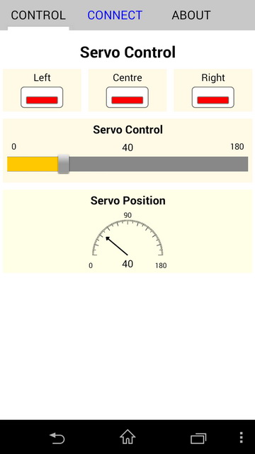
In this example we use a slider to control a single servo. The slider allows us to position the servo at any angle between 0 and 180 degrees.
The servo is a small Tower Pro 9g which is powered from a breadboard power supply. Motors should not be powered directly from the Arduino. The servo has a range of about 180 degrees.
Note: If the servo jitters and jumps it may be due to timer conflicts caused by different libraries using the same timer.
To help avoid this, when using servos it is always better to use hardware serial for serial communication.
Circuit
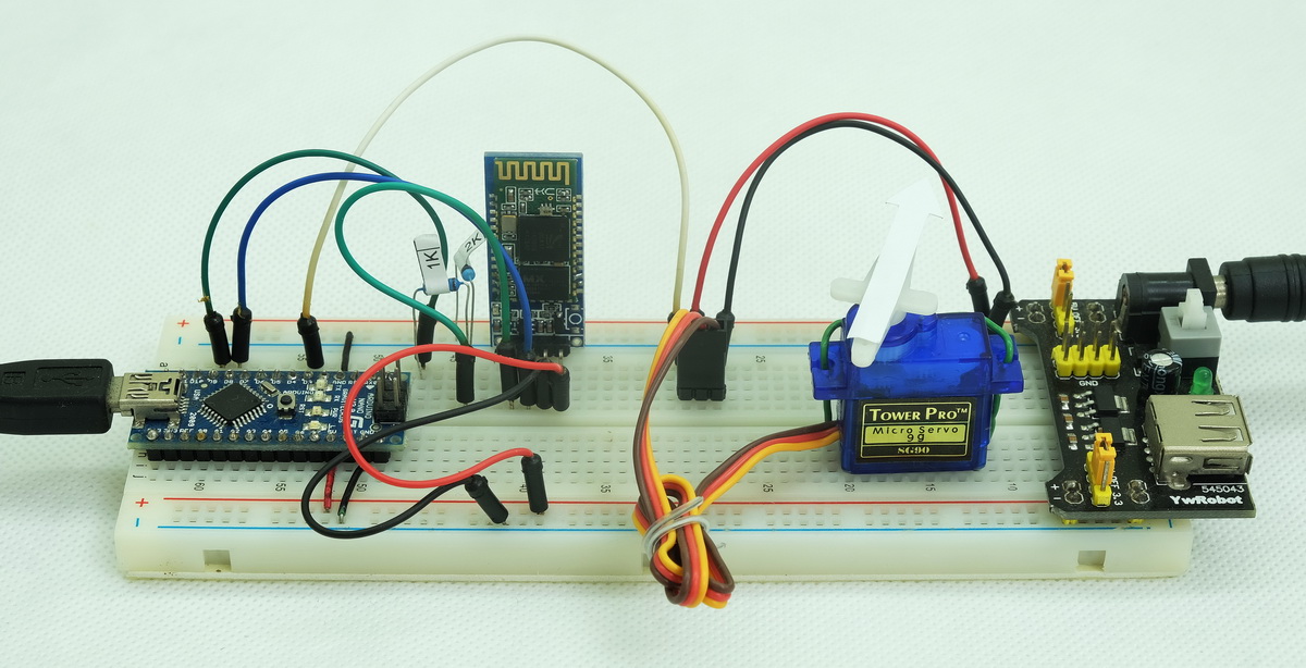
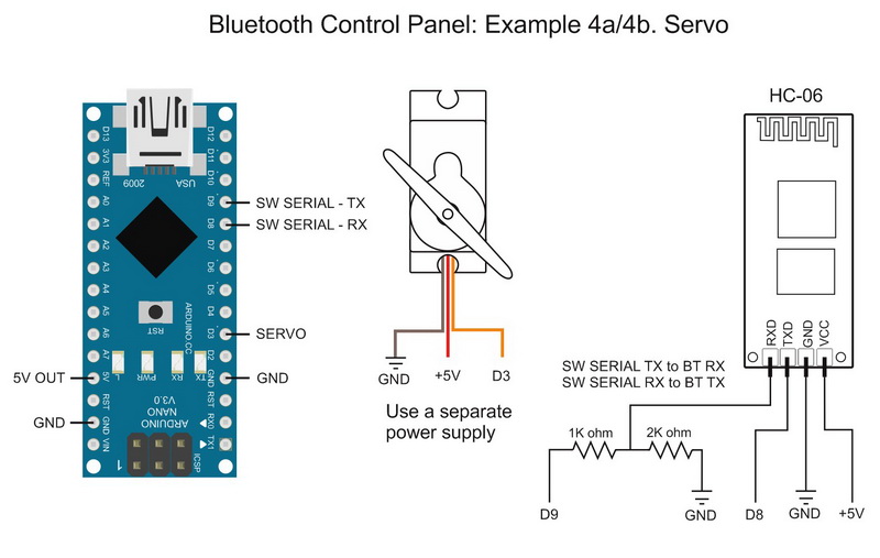
Fairly simple setup; the servo vcc is connected to it’s own power supply (in this case 5V from a breadboard powwer supply), ground is connected to the power supply and also the Arduiono. The servo control line is connected to the Arduino’s D3 pin.
Since we are using AltSoftSerial to talk to the Bluetooth module, the module is connected to pins D8 and D9 on the Arduino.
Arduino sketch
To drive the servo I am using the ServoTimer2 library. This uses the Arduino Timer 2 and works with AltSoftSerial. I have changed the default minimum and maximum pulse values. The libraries default values didn’t give me a full 180 degrees.
In the ServoTimer2.h file, find the following lines:
#define MIN_PULSE_WIDTH 750
#define MAX_PULSE_WIDTH 2250
and change to
#define MIN_PULSE_WIDTH 500
#define MAX_PULSE_WIDTH 2300
After changing the ServoTimer2.h file you will need to reload the Arduino IDE. These are the actual minimum and maximum values for the servo I an using. Yours may be different.
In the setup function;
– the onboard LED is initialized for output,
– pin 3 is initialized as the servo pin, and
– AltSoftSerial is started for communication with the Bluetooth module.
void setup() { // Set the onboard LED pin for output pinMode(13, OUTPUT); digitalWrite(13,LOW); myservo.attach(3); myservo.write(servoMinPulse); // open software serial connection to the Bluetooth module. BTserial.begin(9600); newData = false; initialized = false; startTime = millis(); } // void setup() |
The main loop, while the Arduino is waiting for the CONNECT message the onboard LED is flashed. After a connection is made the LED is turned on. The Arduino then simply checks for incoming data and if it receives a command calls the processCommand function.
void loop() { if (!initialized) { if ( millis()-startTime > 250 ) { startTime = millis(); if (LEDstate == HIGH) { LEDstate = LOW; digitalWrite(13,LOW); } else { LEDstate = HIGH; digitalWrite(13,HIGH); } } recvWithStartEndMarkers(); if (newData) { if (strcmp ("CONNECT",receivedChars) == 0 or strcmp ("RESET",receivedChars) == 0) { sendInitCommands(); } } } if (initialized) { recvWithStartEndMarkers(); // check to see if we have received any new commands if (newData) { processCommand(); } // if we have a new command do something about it } } |
The initialization commands are very basic. There is a TITLE command and a SLIDER command. The SLIDER is set with a minimum of 0 and a maximum of 180.
void sendInitCommands() { BTserial.print("<T,Servo Control>"); BTserial.print("<I,SL,1,Servo Position,0,180,255250230>"); BTserial.print("<EOI>"); delay(100); initialized = true; digitalWrite(13,HIGH); } |
The processCommand function checks for a SLIDER command and if it finds one converts the ascii value to a numeric value and copies it to the variable val. The function then checks to see if the command is for SLIDER number 1. If it is the val value is mapped to the servo pulse value and the servo is moved.
You may notive that the map command looks a little odd. The high value (180) is before the low value (0). What this does is flip the value around; 0 becomes 180 and 180 becomes 0;
servoPulse = map(val,180,0,servoMinPulse,servoMaxPulse); |
This is required because the servo goes from right to left and the SLIDER goes from left to right. Without flipping the value the servo moves in the opposite direction to the SLIDER.
else if (receivedChars[0]== 'S' && receivedChars[1]== 'L') { unsigned int servoPulse = 0; int val = (receivedChars[3]-48) *1000; val = val + (receivedChars[4]-48) * 100; val = val + (receivedChars[5]-48) * 10; val = val + (receivedChars[6]-48); if ( receivedChars[2]== '1' ) { // convert the slider range 0-180 to the servo pulse range of servoMinPulse-servoMaxPulse // the servo is right to left, the slider is left to right so use map to flip the value around servoPulse = map(val,180,0,servoMinPulse,servoMaxPulse); myservo.write(servoPulse); } } |
Download
Dowload the full sketch: Example 4a: Control a Servo
Example 4b: Control a Servo advanced
Here we keep with the servo but add some advanced controls in the form of 3 SMALL SWITCHES which will be used to turn the servo directly to far left, centre and far right. This in itself is not so advanced. The advance bit comes in when we send commands back to the app to turn off the SMALL SWITCHES buttons and update the SLIDER position.
 On its own the app cannot update the slider position when one of the SMALL SWITCHES is clicked. To get round this we send a SLIDER data command back to the app with the new position.
Remember that the SMALL SWITCHES are toggle switches; when clicked they go from green to red to green etc. This means you would normally need to reclick them to turn them back to the off state. A better way is too send a SMALL SWITCH data command from the microprocessor to the app.
For good measure we will add a DIAL to show the servo arm direction/angle.
Circuit
The circuit is exactly the same as the previous example:
Bluetooth module connected to D8 and D9.
Servo connected to D3.
Arduino Skecth
The main structure of the sketch is the same as in example 4a. I have added extra initialization commands to activate the extra control elements and there are extra checks in the processCommand function to cater for the SMALL SWITCHES.
void sendInitCommands() { BTserial.print("<T,Servo Control>"); // Panel title BTserial.print("<I,SS,1,Left,255250230>"); // Activate a SMALL SWITCH BTserial.print("<I,SS,2,Centre,255250230>"); // Activate a SMALL SWITCH BTserial.print("<I,SS,3,Right,255250230>"); // Activate a SMALL SWITCH BTserial.print("<I,SL,1,Servo Control,0,180,255250230>"); // SLIDER BTserial.print("<I,DI,1,Servo Position,0,180,255255230>"); // DIAL BTserial.print("<R,3>"); // Set the app refresh frequency to 30ms BTserial.print("<EOI>"); delay(100); initialized = true; digitalWrite(13,HIGH); if (DEBUG) { Serial.println("Init commands sent"); } } |
In the processCommand function there is an extra command that sends the servo position back to the DIAL in the app.
BTserial.print("<D,DI,1,"); BTserial.print(val); BTserial.print(">"); |
else if (receivedChars[0]== 'S' && receivedChars[1]== 'L') { unsigned int servoPulse = 0; int val = (receivedChars[3]-48) *1000; val = val + (receivedChars[4]-48) * 100; val = val + (receivedChars[5]-48) * 10; val = val + (receivedChars[6]-48); //val = 180-val; if ( receivedChars[2]== '1' ) { // convert the slider range 0-180 to the servo pulse range of 500-2400 servoPulse = map(val,180,0,servoMinPulse,servoMaxPulse); if (DEBUG) { Serial.print("val = "); Serial.print(val);Serial.print(" servoPulse = "); Serial.println(servoPulse); } myservo.write(servoPulse); BTserial.print("<D,DI,1,"); BTserial.print(val); BTserial.print(">"); } } |
There are extra conditions to take care of the SMALL SWITCH commands. First the sketch checks for a SMALL SWITCH command (“SS”) then check to see which switch it is (1,2,or 3). Depending on the switch val is set to the desired postion and a SMALL SWITCH data command is sent to the app to turn the switch back to the off state.
Finally data commands are used to send the new servo postion back to the SLIDER and the DIAL.
else if (receivedChars[0]== 'S' && receivedChars[1]== 'S') { int val = 0; unsigned int servoPulse = 0; if (receivedChars[2]== '1' && receivedChars[3]== '1') // Left { val = 180; BTserial.print("<D,SS,1,0>"); } else if (receivedChars[2]== '2' && receivedChars[3]== '1') // Centre { val = 90; BTserial.print("<D,SS,2,0>"); } else if (receivedChars[2]== '3' && receivedChars[3]== '1') // Right { val = 0; BTserial.print("<D,SS,3,0>"); } servoPulse = map(val,0,180,servoMinPulse,servoMaxPulse); myservo.write(servoPulse); BTserial.print("<D,DI,1,"); BTserial.print(180-val); BTserial.print(">"); BTserial.print("<D,SL,1,"); BTserial.print(180-val); BTserial.print(">"); if (DEBUG) { Serial.print("val = "); Serial.print(180-val);Serial.print(" servoPulse = "); Serial.println(servoPulse); } } |
Download
Dowload the full sketch: Example 4b: Control a Servo advanced
Download the app
Now version 3.
The app is Android only and can be downloaded from Google Play.
or download the app directly. You will need to side load on to your Android device. The direct download is version 3.01. The AYT command is fixed. Download Bluetooth Control Panel.
Changes
Version 3
– Bug fix
Version 2
– fixed the toggle button codes. The app now correctly sends TB
– fixed the large switches. Switch number 3 now changes colour correctly.
– added a RESET command. The app can now be reset from the microprocessor.
Version 1
– initial release.
This looks great. Any idea when it will be available?
hopefully soon, need to find a couple of bugs but difficult to find the time.
may i please get the aia for the bluetooth control panel
It looks really nice!
May I ask which softwate you used to make the app?
It was created in App Inventor
Your apps look very cool and I’m excited to get to play with them this next week. But I’d also really like to be able to customize the user interface a bit more with my own pictures, splash screen, button shapes etc. Please send me an email if you’d be interested in selling a copy of the source code. Thanks!
The app was written in app inventor and I will release the code (the ai file) at some point but not yet. There are still things I want to change and tidy up.
Thanks for the response Martyn. I can understand that. In the meantime, I was hoping if you might be able to give an opinion on a couple things?
I can’t seem to re-establish a proper connection between the arduino and the HC-06 after an error without manually pushing the reset button on the arduino. Would it be possible for me to add a software reset in the arduino code to substitute for manually pushing the button? Maybe even go as far as adding a transistor to bring the reset pin on the arduino low if the ‘reset’ command is sent from the app?
Also, do you think it would be possible for me to modify the arduino code to make the single LED turn off automatically if there is a loss of connection between the HC-06 and the arduino? Or would that need to also be programmed into the app?
Any way you can think of to monitor any of this from the arduino end? I’m at a loss. I appreciate any thoughts! Thanks.
My apologies Martyn. Please ignore my message. You already addressed the reset issue in the instructions for the Arduino Bluetooth Control app. I was digging around, found that and that app actually works better for me too. So if you ever want to make that ABC app open source, I’d love a copy, no matter what state it’s in. Great app!
Hello,
Congratulations for this fantastic app and thanks for sharing!
I am an amateur photographer and I try to realize your “DropController BT”.
I move step by step and I am currently working on the Bluetooth part.
I have a little problem when I try the example with the servo.
The two libraries AltSoftSerial and ServoTimer2 do not work together and generate a compilation error that I do not understand (see under)
Any help is welcome :-)
(and sorry for my english !)
——–
In file included from D:\Data\Documents\Bureau\BCP_Example04a_Servo\BCP_Example04a_Servo.ino:29:0:
C:\Program Files (x86)\Arduino\libraries\ServoTimer2-master/ServoTimer2.h:76:17: error: conflicting declaration ‘typedef uint8_t boolean’
typedef uint8_t boolean;
^
In file included from sketch\BCP_Example04a_Servo.ino.cpp:1:0:
C:\Program Files (x86)\Arduino\hardware\arduino\avr\cores\arduino/Arduino.h:125:14: note: previous declaration as ‘typedef bool boolean’
typedef bool boolean;
^
D:\Data\Documents\Bureau\BCP_Example04a_Servo\BCP_Example04a_Servo.ino: In function ‘void processCommand()’:
D:\Data\Documents\Bureau\BCP_Example04a_Servo\BCP_Example04a_Servo.ino:184:29: warning: deprecated conversion from string constant to ‘char*’ [-Wwrite-strings]
strcpy(“”,receivedChars );
^
exit status 1
Erreur de compilation pour la carte Arduino/Genuino Uno
I think there is a conflict due to the two libraries using the same timer.
Try different servo libraries.
Can I run multiple screens with this software by using multiple initialisation sequences and then using buttons to switch between them?
Looks like you can’t reset the app to load a new screen. However the ‘RESET’ function on the app does it. Could you implement a reset function from the pc end?
I will look at this for the next update, not sure when that will be though.
Thanks Martyn. At the moment I use the top row buttons to page forward and back, home. The button sends an increment page number to the micro. From the app select connect, RESET and the micro gets the reset and outputs the new page. Bit clunky but it sort of works well.
I think the third main window large button is not getting the colour setting correctly. Always appears as red?
Just checked the code for the large switches. Can’t see any obvious reason the colour would not change. Will take a better look when I get time.
Thank you for the feedback. It is very helpful.
Looks like the toggle buttons when pressed respond with BT not TB. Send a D,TB does not write to the button?
Yes, you are correct. No idea why I never noticed I had it wrong in the above description. Been using toggle buttons for a while and never realised I wasn’t using TB….
Added to the list of things to fix.
Just updated the app.
– fixed the toggle button codes.
– fixed the large switches.
– added a RESET command.
I am trying to control 2 LEDs with switches and 1 with PWM control, but I couldn’t initialiaze the commands. This is the code I am using.
#include
AltSoftSerial BTserial;
// Change DEBUG to true to output information to the serial monitor
boolean DEBUG = true;
// Variables used for incoming data
const byte maxDataLength = 20;
char receivedChars[21] ;
boolean newData = false;
// General variables
const byte LED_PIN1 = 10;
const byte LED_PIN2 = 11;
const byte LED_PIN3 = 12;
void setup()
{
// Set the onboard LED pin for output
pinMode(13, OUTPUT);
digitalWrite(13,LOW);
pinMode(LED_PIN1, OUTPUT);
digitalWrite(LED_PIN1,LOW);
pinMode(LED_PIN2, OUTPUT);
digitalWrite(LED_PIN2,LOW);
pinMode(LED_PIN3, OUTPUT);
digitalWrite(LED_PIN3,LOW);
if (DEBUG)
{
// open serial communication for debugging
Serial.begin(9600);
Serial.print(“Sketch: “); Serial.println(__FILE__);
Serial.print(“Uploaded: “); Serial.println(__DATE__);
Serial.println(” “);
}
// Open a software serial connection to the Bluetooth module.
BTserial.begin(9600);
if (DEBUG) { Serial.println(“AltSoftSerial started at 9600″); Serial.println(” “); }
newData = false;
// wait for CONNECT message
boolean connected = false;
while(!connected)
{
recvWithStartEndMarkers();
if (strcmp (“CONNECT”,receivedChars) == 0)
{
connected = true;
if (DEBUG) { Serial.println(“Connected”); }
}
}
receivedChars[0] = ”;
newData = false;
BTserial.print(“”); // Control panel title
BTserial.print(““); // Initialize small switch 1. Switch description = Red LED
BTserial.print(““);
BTserial.print(““);
BTserial.print(“”); // Set the app update speed to 50ms
BTserial.print(“”); // End Of Initialization commands
if (DEBUG) { Serial.println(“Init commands sent”); }
digitalWrite(13,HIGH); // Turn on the on board LED to show we are connected
delay(100); // Small delay to give the app time to set up.
} // void setup()
void loop()
{
recvWithStartEndMarkers(); // Check to see if we have received any new data
if (newData) { processCommand(); } // if we have new data see if it is a command
}
/*
****************************************
* Function processCommand
* parses data commands contained in receivedChars[]
* receivedChars[] has not been checked for errors
*
* passed:
*
* global:
* receivedChars[]
* newData
*
* Returns:
*
* Sets:
* receivedChars[]
* newData
*
*/
void processCommand()
{
if (DEBUG)
{
Serial.print(“receivedChars = “);
Serial.println(receivedChars);
}
if (strcmp (“SW10”,receivedChars) == 0)
{
digitalWrite(LED_PIN1,LOW);
if (DEBUG) { Serial.println(“LED1 LOW”); }
}
if (strcmp (“SW11”,receivedChars) == 0)
{
digitalWrite(LED_PIN1,HIGH);
if (DEBUG) { Serial.println(“LED HIGH”); }
}
if (strcmp (“SW10”,receivedChars) == 0)
{
digitalWrite(LED_PIN2,LOW);
if (DEBUG) { Serial.println(“LED2 LOW”); }
}
if (strcmp (“SW11”,receivedChars) == 0)
{
digitalWrite(LED_PIN2,HIGH);
if (DEBUG) { Serial.println(“LED2 HIGH”); }
}
receivedChars[0] = ”;
newData = false;
}
// function recvWithStartEndMarkers by Robin2 of the Arduino forums
// See http://forum.arduino.cc/index.php?topic=288234.0
/*
****************************************
* Function recvWithStartEndMarkers
* reads serial data and returns the content between a start marker and a end marker.
*
* passed:
*
* global:
* receivedChars[]
* newData
*
* Returns:
*
* Sets:
* newData
* receivedChars
*
*/
void recvWithStartEndMarkers()
{
static boolean recvInProgress = false;
static byte ndx = 0;
char startMarker = ”;
char rc;
if (BTserial.available() > 0)
{
rc = BTserial.read();
if (recvInProgress == true)
{
if (rc != endMarker)
{
receivedChars[ndx] = rc;
ndx++;
if (ndx > maxDataLength) { ndx = maxDataLength; }
}
else
{
receivedChars[ndx] = ”; // terminate the string
recvInProgress = false;
ndx = 0;
newData = true;
}
}
else if (rc == startMarker) { recvInProgress = true; }
}
}
Can you report the initialization commands but use < p r e> and < / p r e> tags around the code (remove the spaces).
The comments function thinks anything in < and > characters is a html tag.
Have you tried example 2 and did it work?
I tried the example with just one LED with small switch, and forgot to mention, that I am using Arduino Uno. But it still stays at “waiting for the initialization commands” .
I changed TX from Bluetooth to arduino’s RX and blutooth’s RX to arduino’s TX and it works, but I still have to work on the code. Thanks.
Can you help me with the code in processcomand for fading LED, I couldn’t manage it to make it work? Thank you.
I can’t help with the code but look at https://www.martyncurrey.com/arduinobtcontrol/. See how the sketch handles the slider command coming from the Android app.
I managed to do it, using this:
if (receivedChars[0]== ‘S’ && receivedChars[1]== ‘L’)
{
byte val = (receivedChars[3]-48) *1000;
val = val + (receivedChars[4]-48) * 100;
val = val + (receivedChars[5]-48) * 10;
val = val + (receivedChars[6]-48);
analogWrite(LED_PIN3, val);
}
Ciao Martyn,
great job!
just a question about the command … it seems not working.
in my code I have: BTserial.print(“”);
the app list it on the ERRORS as : “Invalid command type: [AYT]”
Best regards!
sorry…. html!
in my code I’ve: BTserial.print(“AYT”);
It looks like I broke the AYT command last time I did an update :(
I will try to fix it when I get time.
How do you send a variable number to the control panel from the arduino?
All values are sent as asccii, not values.
To help further pls give more details about what you want to do.
Whether this app work with raspberry or not??
I haven’t tried but it should do. You will need to connect a Bluetooth module to the PI – something like https://blog.miguelgrinberg.com/post/a-cheap-bluetooth-serial-port-for-your-raspberry-pi
After you have this connected just send the commands / data to the app.
Have you got to the point where you can release the AIA file for App Inventor? Thanks!!
Thank you for the program!
But AYT not working. It’s hard to live without it.
Please fix it.
I’ve been meaning to fix that forever.
I haven’t update Google Play yet but you can download the new apk file from https://www.martyncurrey.com/?wpdmdl=7183
martyn,
great app. gives a lot of possibilities to interface whatever we want however we want.
but i cannot seem to get any communication from the app to my arduino mega. the initialization commands get to the app, but in the serial monitor no data from the app shows up. also changed the RX pin to a normal digital pin in stead of a PWS pin. nothing changes.
all is working normally on my arduino uno.
hope you got some ideas on this
Use a BT terminal app to confirm the connection is working.
Have a look at https://www.martyncurrey.com/arduino-with-hc-05-bluetooth-module-in-slave-mode/
Hello Martyn,
how do i put the result of a float into the following command?
The result should be at the ‘temp’ location.
BTserial.print(“”);
Regards
Chris
Anything further on a Bluetooth 4 (or 5) version? Wouldn’t this require a custom BLE service?
Hi,
I am quite new to Arduino and I have made the “Example 2: Controlling an LED”, and curiously digitalWrite(LED_RED_PIN, Low) causes the LED to light while HIGH causes the LED to be OFF.
Any idea?
All I can think of is you have the LED the opposite way around and connected to vcc rather than ground. This would then mean when the Arduino pin is HIGH the LED is off and when the Arduino pin is LOW the LED is on.
Hello Martyn,
I try to use your BCP for a simple task and found a minor issue. Controlling a ledstrip (only white) and a ledstrip RGBW would require 5 PWM’s.
The UNO has the pins 3,5,6,9,10,11 so that would be fine.
However the uses pin 9 and disables the use of pin 10, so only 4 PWM’s are left.
My question: Are there other options to use the HC-05 BT module in combination with BCP, like for instance the softwareSerial.h which has the possibility to use other pins than pin 8 and 9 ?
Regards Chris
Any software serial library can be used. Just change the sketch to include the one you want to use.
I used AltSoftSerial because it is faster and more robust than the default software serial library.
Dear Martyn,
I used the Arduino’s EEPROM to save and recall the position of SS (small switches) and SL (slider) with the help of “boolean” (position on or off) and “int” (slider value)
I used “Data commands from the microprocessor” to set the SS in the correct state and the SL in the correct position as it was saved in the EEPROM.
These “Data commands” I did put within the ‘void sendInitCommands()’
See part of this void below:
BTserial.print(““); // small switch 4 named WW
BTserial.print(““); // slider 3 named Dimmer-white
if (White == 0) {
BTserial.print(“”); // SS 4 should be switched off or lit red
Serial.print(“White is low”);
analogWrite(WHITE_LED_PIN, 0); // pwm to 0
}
if (White == 1) {
BTserial.print(“”); // SS 4 should be switched on or lit green BUT DOES NOT
Serial.print(“White is high”);
BTserial.print(“”); // SL 3 should be in position valW BUT DOES NOT
analogWrite(WHITE_LED_PIN, PWMvalueW); // pwm to value from EEPROM
}
BTserial.print(“”); // Set the app update speed to 50ms
BTserial.print(“”); // End Of Initialization commands
Serial.println(“BT initialisation done “);
My Questions:
Are the “Data commands from the microprocessor” (mentioned below) allowed within the ‘void sendInitCommands()’ which is part of the ‘void setup()’, or should they be allocated within ‘void processCommand()’ which is part of the loop?
BTserial.print(“”);
BTserial.print(“”);
Are other non-Btserial commands (as analogWrite(WHITE_LED_PIN, PWMvalueW); ) allowed in that BT-initialisation block?
Regards C
Dear Martyn,
I am working on a Arduino /android project and your work has helped me a lot. However I need more of your help regarding Value Control a no examples for the same are given. If we need to feed some control value from App to arduino how to do the same.
Regards
Hard to say without further information, however, if you want to send a single command or send infrequent commands you can use the text box.
Thanks Martyn, I will try text box and then let you know.
“BTserial.print(“”);”
showing Temperature and not it’s Value
I think the comment system is messing up the command.
I was about to say have a look at example 3 only to find its not there…. Looks like I reverted to an earlier version of the guide at some point without realising.
You need to send the temperature value not a string. This means you need to either build the command before sending it or send the command in pieces. The easiest way is to send it in pieces. For example
<D,VL,1,22.4°> = Value at position 1, display 22.4°
BTserial.print(“<D,VL,1,”);
BTserial.print(temperature);
BTserial.print(“>”);
Its working, thanks.
Very nice tutorial, very well expalined, thanks, we also use this APP to control relays via bluetooth:
https://play.google.com/store/apps/details?id=net.sabro.bluetoothrelays
Dear Martyn,
Kindly share your AIA file of app inventor for the bt control panel for making some customization’s in interface for our application. Thanks
Thanks for sharing such an amazing articles.
I am trying to pair a HC-05 module to a Raspberry pi 4B. Every time I do so the module connects then disconnects 2 seconds later. I have successfully paired two of these modules together. I have also used different brands of the HC-05 modules, both types pair to the Ras pi but than disconnects from Ras Pi and on Windows 11 computer (2 different tests) 2 sec later.
What might be causing the BT module to disconnect?