In the final part of the Arduino serial guide I finish with slightly more advanced examples using start and end markers surrounding the data.
Example 6: Arduino to Arduino Serial Communication Using Start and End Markers
Using start and end markers is my preferred method for serial data when speed is not a priority. To make things a little easier on myself I also use ascii for numbers and try to use fixed length data where ever possible. You can see more examples here and here.
Start and end markers is not original and is based on (or simply copied) from a post by Robin2 on the Arduino forum. I started using this function a while ago, liked it and have used it ever since.
Robin2’s function
void recvWithStartEndMarkers()
{
     static boolean recvInProgress = false;
     static byte ndx = 0;
     char startMarker = '[';
     char endMarker = ']';
     char rc;

     if (Serial.available() > 0)
     {
          rc = Serial.read();
          if (recvInProgress == true)
          {
               if (rc != endMarker)
               {
                    receivedChars[ndx] = rc;
                    ndx++;
                    if (ndx > maxDataLength) { ndx = maxDataLength; }
               }
               else
               {
                     receivedChars[ndx] = '\0'; // terminate the string
                     recvInProgress = false;
                     ndx = 0;
                     newData = true;
               }
          }
          else if (rc == startMarker) { recvInProgress = true; }
     }
}
I use square brackets ([ and ]) as start and end markers which can be changed should you wish. It’s important to pick characters that will not be used in the data though.
The function reads the serial input buffer until it finds a start marker, it then starts to copy data to the buffer called receivedChars. When it finds the end marker it stops copying and sets newData true. Anything not inside the markers is ignored.
Give it a try
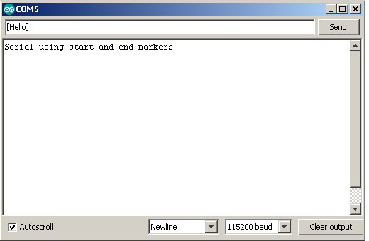
Upload the following sketch, open the serial monitor and enter something. If you use the start and end markers, what ever is contained in the markers will be displayed in the serial monitor. Anything outside the markers will be ignored.
// Example 6a: Arduino to Arduino Serial Communication Using Start and End Markers
// www.martyncurrey.com
const byte maxDataLength = 30; // maxDataLength is the maximum length allowed for received data.
char receivedChars[31] ;
boolean newData = false; // newData is used to determine if there is a new command
void setup()
{
Serial.begin(115200);
Serial.println("Serial using start and end markers");
newData = false;
}
void loop()
{
recvWithStartEndMarkers(); // check to see if we have received any new commands
if (newData) { processCommand(); } // if we have a new command do something
}
void processCommand()
{
Serial.print("Recieved data = "); Serial.println(receivedChars);
newData = false;
}
// function recvWithStartEndMarkers by Robin2 of the Arduino forums
// See http://forum.arduino.cc/index.php?topic=288234.0
void recvWithStartEndMarkers()
{
static boolean recvInProgress = false;
static byte ndx = 0;
char startMarker = '[';
char endMarker = ']';
if (Serial.available() > 0)
{
char rc = Serial.read();
if (recvInProgress == true)
{
if (rc != endMarker)
{
if (ndx < maxDataLength) { receivedChars[ndx] = rc; ndx++; }
}
else
{
receivedChars[ndx] = '\0'; // terminate the string
recvInProgress = false;
ndx = 0;
newData = true;
}
}
else if (rc == startMarker) { recvInProgress = true; }
}
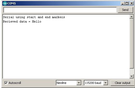
}In the serial monitor enter “[hello]”
Now try entering “This will be ignored[This will be processed]”
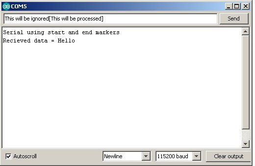

The data outside of the start and end markers is ignored.
The only drawback to this method is that the data cannot contain the start and end markers without using special techniques like control codes. You can off course use any value or character for the markers.
Let’s adapt the EOL example to use start and end markers
Example 7: Arduino to Arduino Serial Communication Using Start and End Markers
// Example 7: Arduino to Arduino Serial Communication Using Start and End Markers. Master
// www.martyncurrey.com

#include <AltSoftSerial.h>
AltSoftSerial ALTserial;

byte switchPin = 2;              //  input pin for the switch
boolean newSwitchState1 = LOW;   // used for simple debouce
boolean newSwitchState2 = LOW;
boolean newSwitchState3 = LOW;
boolean oldSwitchState = LOW;    // variable to hold the switch state

int potPin = A0;    // input pin for the potentiometer
int val = 0;        // variable to store the value coming from the pot
int oldval = 0;     // variable to store the old pot value

unsigned long startTime = 0;
unsigned long nowTime = 0;
unsigned long waitTime = 500;


void setup()
{
  Serial.begin(9600);
  Serial.println("Press the button switch or twiddle the pot.");

  ALTserial.begin(9600);

  pinMode(switchPin, INPUT);
  startTime = millis();
}

void loop()
{
    newSwitchState1 = digitalRead(switchPin);     delay(1);
    newSwitchState2 = digitalRead(switchPin);     delay(1);
    newSwitchState3 = digitalRead(switchPin);

    // Simple debouce - if all 3 values are the same we can continue
    if (  (newSwitchState1==newSwitchState2) && (newSwitchState1==newSwitchState3) )
    {
        // only interested if the switch has changed state. HIGH to LOW or LOW to HIGH
        if ( newSwitchState1 != oldSwitchState )
        {
           oldSwitchState = newSwitchState1;

           // has the button switch been closed?
           if ( newSwitchState1 == HIGH )
           {
                 Serial.println("[S=HIGH]");
                 ALTserial.print("[S=HIGH]");
           }
           else
           {
                Serial.println("[S=LOW]");
                ALTserial.print("[S=LOW]");
           }
        }
    }

    // only want to check the pot every 500 ms (change this if you like)
    // and only want to send if the value has changed

    nowTime = millis();
    if (nowTime - startTime > waitTime)
    {
      startTime = nowTime;
      val = analogRead(potPin);
      if ((val) != (oldval) )
      {
        oldval = val;
        Serial.print("[P=");
        HS_printFixedFormat(val);
        Serial.println("]");

        ALTserial.print("[P=");
        ALT_printFixedFormat(val);
        ALTserial.print("]");
      }
    }
}


void ALT_printFixedFormat(int num)
{
  if (num <1000) {  ALTserial.print("0");    }
  if (num <100)  {  ALTserial.print("0");    }
  if (num <10)   {  ALTserial.print("0");    }
  ALTserial.print(num);

}

void HS_printFixedFormat(int num)
{
  if (num <1000) {  Serial.print("0");    }
  if (num <100)  {  Serial.print("0");    }
  if (num <10)   {  Serial.print("0");    }
  Serial.print(num);
}
// Example 7: Arduino to Arduino Serial Communication Using Start and End Markers. Slave
// www.martyncurrey.com
#include <AltSoftSerial.h>
AltSoftSerial ALTserial;
#include <Wire.h>
#include <LiquidCrystal_I2C.h>
//LiquidCrystal_I2C lcd(0x27, 2, 1, 0, 4, 5, 6, 7, 3, POSITIVE);
// Set the pins on the I2C chip used for LCD connections:
// addr, en,rw,rs,d4,d5,d6,d7,bl,blpol
LiquidCrystal_I2C lcd(0x27, 2, 1, 0, 4, 5, 6, 7, 3, POSITIVE); // Set the LCD I2C address
char c;
int length = 30;
char buffer [31];
boolean haveNewData = false;
void setup()
{
Serial.begin(9600);
Serial.println("Ready");
ALTserial.begin(9600);
lcd.begin(20, 4);
lcd.setCursor(0, 0);
lcd.print("Arduino Serial");
lcd.setCursor(0, 1); lcd.print("Switch=");
lcd.setCursor(0, 2); lcd.print("Pot=");
}
void loop()
{
recvWithStartEndMarkers();
if ( haveNewData ) { processNewData(); }
}
void recvWithStartEndMarkers()
{
static boolean recvInProgress = false;
static byte ndx = 0;
char startMarker = '[';
char endMarker = ']';
char rc;
if (ALTserial.available() > 0)
{
rc = ALTserial.read();
if (recvInProgress == true)
{
if (rc != endMarker)
{
buffer[ndx] = rc;
ndx++;
if (ndx > length) { ndx = length; }
}
else
{
buffer[ndx] = '\0'; // terminate the string
recvInProgress = false;
ndx = 0;
haveNewData = true;
}
}
else if (rc == startMarker) { recvInProgress = true; }
}
}
void processNewData()
{
Serial.println(buffer);
if (buffer[0] == 'S')
{
lcd.setCursor(7, 1);
if (buffer[2] == 'H') { lcd.print("HIGH"); }
if (buffer[2] == 'L') { lcd.print("LOW "); }
}
if (buffer[0] == 'P')
{
lcd.setCursor(4, 2);
char temp[5];
temp[0] = buffer[2];
temp[1] = buffer[3];
temp[2] = buffer[4];
temp[3] = buffer[5];
temp[4] = '\0' ;
lcd.print( temp);
}
haveNewData = false;
buffer[0] = '\0';
}The sketches do exactly the same as in the previous example. The only difference is I am now using start and end markers
In the master sketch start and end markers have been added to the data
ALTserial.print("[S=HIGH]");
...
ALTserial.print("[S=LOW]");
and in the slave sketch the recvWithStartEndMarkers() function replaces the readSerial(). Everything else is the same.
Example 8: Advanced example. Non blocking Serial Communication
I mentioned above that one of the benefits of using your own functions rather than those built in to the Arduino core is that with your own functions the Arduino can do other things while still receiving serial data. Using the functions from the Arduino core, such as readBytesUntil() block the Arduino.
To show how not blocking may be useful, the next example adds a flashing LED. When the pot value goes above a certain level the LED starts to flash. The master sketch remains the same as above. The slave sketch is updated to include the new code (which is very similar to the potentiometer timing check code used in the master sketch).<div class=”whiteSpace1″> </div>
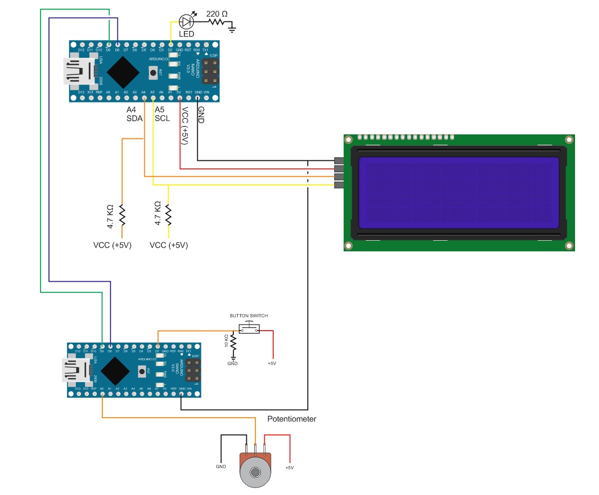
I have added an LED to pin D2 on the master device
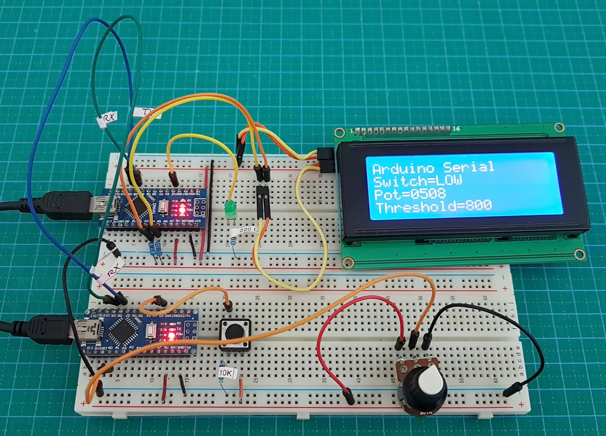
The LED is actually used :-)
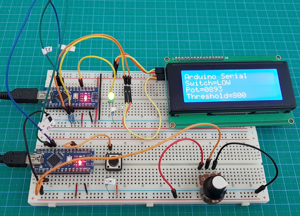
When the pot value is below the threshold the LED is off. When the pot value goes above the threshold the LED starts to flash.
The sketch used for the master device is exactly the same as used in example 7.
// Example 8: Advanced example. Non blocking Serial Communication With Blinking LED. Master
// www.martyncurrey.com

#include <AltSoftSerial.h>
AltSoftSerial ALTserial;

byte switchPin = 2;              //  input pin for the switch
boolean newSwitchState1 = LOW;   // used for simple debouce
boolean newSwitchState2 = LOW;
boolean newSwitchState3 = LOW;
boolean oldSwitchState = LOW;    // variable to hold the switch state

int potPin = A0;    // input pin for the potentiometer
int val = 0;        // variable to store the value coming from the pot
int oldval = 0;     // variable to store the old pot value

unsigned long startTime = 0;
unsigned long nowTime = 0;
unsigned long waitTime = 500;


void setup()
{
  Serial.begin(9600);
  Serial.println("Press the button switch or twiddle the pot.");

  ALTserial.begin(9600);

  pinMode(switchPin, INPUT);
  startTime = millis();
}

void loop()
{
    newSwitchState1 = digitalRead(switchPin);     delay(1);
    newSwitchState2 = digitalRead(switchPin);     delay(1);
    newSwitchState3 = digitalRead(switchPin);

    // Simple debouce - if all 3 values are the same we can continue
    if (  (newSwitchState1==newSwitchState2) && (newSwitchState1==newSwitchState3) )
    {
        // only interested if the switch has changed state. HIGH to LOW or LOW to HIGH
        if ( newSwitchState1 != oldSwitchState )
        {
           oldSwitchState = newSwitchState1;

           // has the button switch been closed?
           if ( newSwitchState1 == HIGH )
           {
                 Serial.println("[S=HIGH]");
                 ALTserial.print("[S=HIGH]");
           }
           else
           {
                Serial.println("[S=LOW]");
                ALTserial.print("[S=LOW]");
           }
        }
    }

    // only want to check the pot every 500 ms (change this if you like)
    // and only want to send if the value has changed

    nowTime = millis();
    if (nowTime - startTime > waitTime)
    {
      startTime = nowTime;
      val = analogRead(potPin);
      if ((val) != (oldval) )
      {
        oldval = val;
        Serial.print("[P=");
        HS_printFixedFormat(val);
        Serial.println("]");

        ALTserial.print("[P=");
        ALT_printFixedFormat(val);
        ALTserial.print("]");
      }
    }
}


void ALT_printFixedFormat(int num)
{
  if (num <1000) {  ALTserial.print("0");    }
  if (num <100)  {  ALTserial.print("0");    }
  if (num <10)   {  ALTserial.print("0");    }
  ALTserial.print(num);

}

void HS_printFixedFormat(int num)
{
  if (num <1000) {  Serial.print("0");    }
  if (num <100)  {  Serial.print("0");    }
  if (num <10)   {  Serial.print("0");    }
  Serial.print(num);
}
The sketch on the slave device has been updated with the code to blink the LED.
// Example 8: Advanced example. Non blocking Serial Communication With Blinking LED. Slave
// www.martyncurrey.com

#include <AltSoftSerial.h>
AltSoftSerial ALTserial;

#include <Wire.h>
#include <LiquidCrystal_I2C.h>
//LiquidCrystal_I2C lcd(0x27, 2, 1, 0, 4, 5, 6, 7, 3, POSITIVE);

// Set the pins on the I2C chip used for LCD connections:
//                    addr, en,rw,rs,d4,d5,d6,d7,bl,blpol
LiquidCrystal_I2C lcd(0x27, 2, 1, 0, 4, 5, 6, 7, 3, POSITIVE);  // Set the LCD I2C address

char c;
int length = 30;
char buffer [31];
boolean haveNewData = false;

int potVal = 0;
int warningThreshold = 800;
unsigned long startTime = 0;
unsigned long nowTime = 0;
unsigned long flashRate = 250;

byte LEDpin = 2;
boolean LEDflash = false;
boolean LEDstate = false;


void setup()
{
  Serial.begin(9600);
  Serial.println("Ready");

  ALTserial.begin(9600);

  lcd.begin(20, 4);
  lcd.setCursor(0, 0);
  lcd.print("Arduino Serial");
  lcd.setCursor(0, 1);  lcd.print("Switch=LOW");
  lcd.setCursor(0, 2);  lcd.print("Pot=0000");
  lcd.setCursor(0, 3);  lcd.print("Threshold="); lcd.print(warningThreshold);

  pinMode(LEDpin, OUTPUT);
  boolean LEDstate = LOW;
}


void loop()
{
  recvWithStartEndMarkers();
  if ( haveNewData == true )  { processNewData();  }
  if ( LEDflash == true)      { flashTheLED(); }
}


void flashTheLED()
{
    nowTime = millis();
    if (nowTime - startTime > flashRate)
    {
      startTime = nowTime;

      if (LEDstate == LOW)
      {
         LEDstate = HIGH;
         digitalWrite(LEDpin, HIGH);
      }
      else
      {
         LEDstate = LOW;
         digitalWrite(LEDpin, LOW);
      }
    }
}


void recvWithStartEndMarkers()
{
     static boolean recvInProgress = false;
     static byte ndx = 0;
     char startMarker = '[';
     char endMarker = ']';
     char rc;

     if (ALTserial.available() > 0)
     {
          rc = ALTserial.read();

          if (recvInProgress == true)
          {
               if (rc != endMarker)
               {
                    buffer[ndx] = rc;
                    ndx++;
                    if (ndx > length) { ndx = length; }
               }
               else
               {
                     buffer[ndx] = '\0'; // terminate the string
                     recvInProgress = false;
                     ndx = 0;
                     haveNewData = true;
               }
          }
          else if (rc == startMarker) { recvInProgress = true; }
     }
}


void processNewData()
{
  Serial.println(buffer);
  if (buffer[0] == 'S')
  {
    lcd.setCursor(7, 1);
    if (buffer[2] == 'H') {   lcd.print("HIGH");    }
    if (buffer[2] == 'L') {   lcd.print("LOW ");    }
  }

  if (buffer[0] == 'P')
  {
      lcd.setCursor(4, 2);
      char temp[5];
      temp[0] = buffer[2];
      temp[1] = buffer[3];
      temp[2] = buffer[4];
      temp[3] = buffer[5];
      temp[4] = '\0' ;
      lcd.print( temp);

      potVal = atoi(temp);
      if (potVal >= warningThreshold)
      {
       LEDflash = true;
      }
      else
      {
        LEDflash = false;
        // just in case the LED is on when the pot value goes below the threshold
        digitalWrite(LEDpin,LOW);
      }
  }

  haveNewData = false;
  buffer[0] = '\0';
}
A few things to note about the new sketch.
I am using the actual numeric value of the pot. This means I have to convert the ascii value to the actual value. I do this using atoi() or ascii to integer.
LEDflash is used to show if the LED should be flashing or not.
potVal = atoi(temp);
if (potVal >= warningThreshold)
{
   LEDflash = true;
}
else
{
   LEDflash = false;
   // just in case the LED is on when the pot value goes below the threshold
   digitalWrite(LEDpin,LOW);
}
It is possible that the LED is on when the value of the pot goes below the threshold and the flashing stops. So to make sure the LED is off when this happens I set LEDpin LOW. You could check LEDstatus if you wished and only set the pin LOW if the LED is on but there isn’t really any reason to.
Thanks to using functions, the main loop() if fairly basic, just three lines of code.
Check for serial data.
Check for new data
Maybe flash the LED.
void loop()
{
  recvWithStartEndMarkers();
  if ( haveNewData == true )  { processNewData();  }
  if ( LEDflash == true)      { flashTheLED(); }
}
The flashTheLED() function checks how much time has passed and if the time is greater than the blink rate it switches the LED on or off accordingly.
void flashTheLED()
{
    nowTime = millis();
    if (nowTime - startTime > flashRate)
    {
      startTime = nowTime;

      if (LEDstate == LOW)
      {
         LEDstate = HIGH;
         digitalWrite(LEDpin, HIGH);
      }
      else
      {
         LEDstate = LOW;
         digitalWrite(LEDpin, LOW);
      }
    }
}
Things to Try
The threshold value is hard coded and if you wish to change it you need to update the code and reupload to the Arduino. Try adding a function so that the button switch on the master device sets the threshold limit. IE set the pot value to the threshold value you want and click the button switch to set. Of course, you need to send the new threshold value to the slave device and then use the value to set the threshold limit. I will leave you to try this.
That’s it. Hopefully these guides are a decent introduction to serial data and how to implement it in your own projects.