The Arduino Mega has 4 hardware serial channels so we do not need to use software serial, we can use one of the extra hardware serials to talk to the Bluetooth module. In the below example I using serial1 to talk to the HC-05.
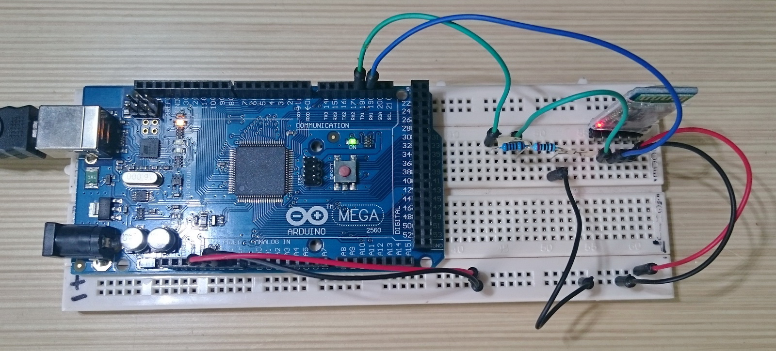
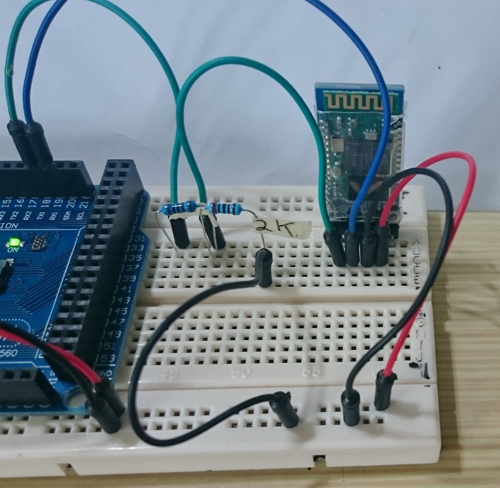
Connections
The HC-05 zs-040 modules have a voltage regular on then vcc in line. This means they can accept an in voltage from 3.6 to 6v and can be powered from the Arduinos 5V out. However, the data pins are not 5v, they are 3.3v only. This means we need to reduce the 5v from the Arduino TX pin to 3.3v. One easy method is to use a voltage divider made from a couple of resistors. I am using a 1K ohm and a 2K ohm resistor.
The Arduino will read 3.3v as HIGH which means we do not need to convert the BT TX to Arduino RX line. We can make a direct connection
Arduino 5V out to HC-05 VCC
Arduino GND to HC-05 GND
Arduino TX1/Pin18 to voltage divider and then to HC-05 RX
Arduino RX1/Pin 19 to HC-05 TX
The voltage divider is using a 1K ohm resistor and a 2K ohm resistor.
Arduino Sketch
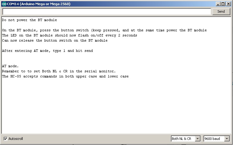
The following sketch waits for the user to put the HC-05 in to AT mode and then simply copies what ever is entered in the serial monitor to the HC-05.
Load the following sketch in to the Arduino Mega
// Basic Bluetooth test sketch 5a for the Arduino Mega. // AT mode using button switch // HC-05 with EN pin and button switch // // Uses serial with the host computer and serial1 for communication with the Bluetooth module // // Pins // BT VCC to Arduino 5V out. Disconnect before running the sketch // BT GND to Arduino GND // BT RX (through a voltage divider) to Arduino TX1 (pin 18) // BT TX to Arduino RX1 (no need voltage divider) (pin 19) // // When a command is entered in to the serial monitor on the computer // the Arduino will relay it to the Bluetooth module and display the result. // char serialByte = '0'; const byte LEDPIN = 13; void setup() { pinMode(LEDPIN, OUTPUT); // communication with the host computer Serial.begin(9600); Serial.println("Do not power the BT module"); Serial.println(" "); Serial.println("On the BT module, press the button switch (keep pressed, and at the same time power the BT module"); Serial.println("The LED on the BT module should now flash on/off every 2 seconds"); Serial.println("Can now release the button switch on the BT module"); Serial.println(" "); Serial.println("After entering AT mode, type 1 and hit send"); Serial.println(" "); // wait for the user to type "1" in the serial monitor while (serialByte !='1') { if ( Serial1.available() ) { serialByte = Serial1.read(); } } // communication with the BT module on serial1 Serial1.begin(38400); // LED to show we have started the serial channels digitalWrite(LEDPIN, HIGH); Serial.println(" "); Serial.println("AT mode."); Serial.println("Remember to to set Both NL & CR in the serial monitor."); Serial.println("The HC-05 accepts commands in both upper case and lower case"); Serial.println(" "); } void loop() { // listen for communication from the BT module and then write it to the serial monitor if ( Serial1.available() ) { Serial.write( Serial1.read() ); } // listen for user input and send it to the HC-05 if ( Serial.available() ) { Serial1.write( Serial.read() ); } } |
When you first power on, the LED on the BT module will flash quickly, about 5 (I think) times per second.
To change to AT mode. Remove power to the HC-05, press and hold the little button switch, reconnect power (while the button switch is held closed). The flash on the LED should change to on/off every 2 seconds, 1 second on, 1 second off. This indicates AT mode. You can now release the button switch.
The button switch, when closed, connects pin 34 of the small BT module to 3.3v. When pin 34 is HIGH on start up, the module goes in to AT Mode. Releasing the button switch takes pin 34 back to not connected and this puts the module in to a “mini” AT mode and not all commands work. There is also a “full” AT Mode which requires pin 34 to be HIGH all the time.
Open the serial monitor. You should see:
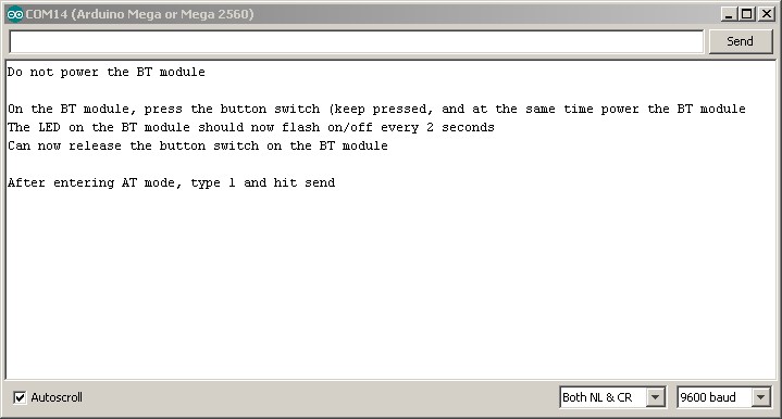
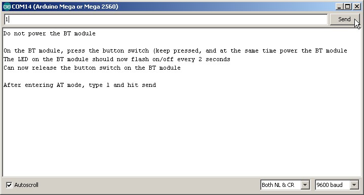
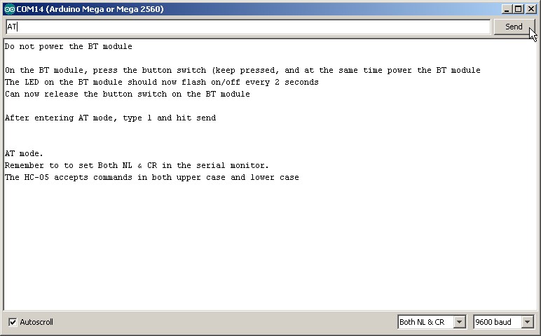
Put the HS-05 in to AT mode and then enter “1” (no quotes) and hit send:
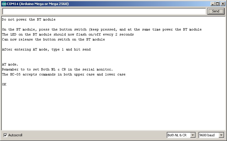
To confirm everything is working enter AT and hit send. If all is well you will see “OK”. If you get error(0). Re-enter the “AT”. The error means extra characters have not been cleared from the serial buffer.
To change the role to MASTER use: AT+ROLE=1\r\n. Note the equals sign. These module expect an equals sign.
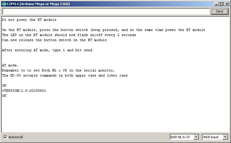
To check the firmware version on the HC-05. Enter AT+VERSION:
Updated 30.07.2015
The below sketch is for Jesus and was not tested at the time of posting.
Connect the HC-05 as in the above photo,
upload the sketch to the Arduino Mega,
pair the HC-05 with an Android device,
open Bluetooth Terminal,
connect to the HC-05.
that should be it….
// Basic Bluetooth test sketch 5b for the Arduino Mega. // simple communication with an Android device // // Uses serial with the host computer and serial1 for communication with the Bluetooth module // // Pins // BT VCC to Arduino 5V out. Disconnect before running the sketch // BT GND to Arduino GND // BT RX (through a voltage divider) to Arduino TX1 (pin 18) // BT TX to Arduino RX1 (no need voltage divider) (pin 19) // // When text is entered in to the serial monitor on the computer the // Arduino will relay it to the Bluetooth module. // When text is entered in to a Bluetooth terminal on the Android device // it will be sent to the Arduino and be displayed in the serial monitor // char c = '0'; void setup() { // communication with the host computer Serial.begin(9600); Serial.println("Do not power the BT module"); // communication with the BT module on serial1 Serial1.begin(9600); Serial.println(" "); Serial.println("HC-05 started at 9600"); Serial.println("Remember to to set Both NL & CR in the serial monitor."); Serial.println("Do not enter AT mode"); Serial.println(""); } void loop() { // listen for communication from the BT module and then write it to the serial monitor if ( Serial1.available() ) { c = Serial1.read(); Serial.write( c ); } // listen for user input and send it to the HC-05 if ( Serial.available() ) { c = Serial.read(); Serial1.write( c ); } } |
Hi Martyn,
Thanks for your effort.
Your sketch works fine now for me.
I could resolve the problem I had.
Now it seems very easy, at the end, but I was very busy looking for the bug.
Best Regards
Good to hear you got it working.
I’m sorry for bothering you, bro.
But, I’ve done everything as you said and I still can’t receive any answer from BT module when typing “1” or “AT” (without cotes). Everything is equal you did, except by res (660 ohms and 330 ohms) and the module (FC-114/HC-05, but I think they both are the same).
Do you have any clue about what could be causing the lack of transmission?
PS.: I changed the pins 18 to 19 and vice-versa, but nothing changed.
Hugs
The FC-114 modules have a different firmware and are in AT mode when they start.
see https://www.martyncurrey.com/hc-05-fc-114-and-hc-06-fc-114-first-look/ and https://www.martyncurrey.com/hc-05-fc-114-and-hc-06-fc-114-part-2-basic-at-commands/
hi martyn,
how would I put the HC 06 JY MCU to AT mode?
thank you :)
I haven’t used the JY-MCU boards but the HC-06 should be in AT mode on start up. The default baud rate is usually 9600.
Connect using 9600 and enter AT in the serial monitor. The HC-06 does not like to have carriage return and new line characters so set the serial monitor to “No line ending”. You should get an “OK” reply.
HC-06s have a very limited number of AT commands. See https://www.martyncurrey.com/arduino-and-hc-06-zs-040/
Hello,
Thanks for your article!! It really help me a lot to setup bluetooth communication. I am able to transmit data from the Arduino zero board to bluetooth terminal but vice versa is not happening. Any clue on this?
Note: I have not put voltage divider circuit on transmit line( HC-05 RX to Arduino pin D3 (TX) via a voltage divider) but as per my understanding transmission from Arduino zero board to bluetooth terminal should be affected because of this and not reception.
Thanks for your help in advance.
Best Regards,
Hemal Bavishi
Yes, since the Zero is a 3.3v device it does not need a voltage divider.
Are you using software serial or hardware serial?
Please note I don’t have a Zero and my knowledge about them is very limited.
Why does this example show a voltage divider? Arduino Mega comes equipped with a 3.3 v pin. Seems like more work than necessary.
The voltage divider in on the data line (Arduino TX to BT RX) not the power line. The Mega data pins are 5V.
good morning i have same hco5 with couple 1,5ohm resistors 5v->2,5v what do you think will i get my at commands back into serial monitor? or it will not work?
I honestly don’t know but I doubt it. Normally 1.8v is the minimum for a HIGH. All I can suggest is try it and see if it works.
hello…. can i interface this bluetooth module with raspberry pi?
yes but I have no idea how.
Hi. U say we need resistors between arduino Tx and hc05 rx. Okay i got the logic but i dont understand something u just only connect one of these resistors between arduino tx to BT rx. Because in pic u seperate and use 2.nd resistor to connect GNd. I completely am lost!
This not something I can answer directly. It all depends on your final sketch / project. However, the 328P Arduinos are more widely used and better supported. For somebody learning Arduino it may be better to stay with one of the regular boards.
Personally, I use 328P based Nanos for almost everything. I have a couple of Megas but they never get used. I learnt far more squeezing large sketches in to the small Arduinos than I would ever have if I simply used a mega but my motivation may be different to yours. For me the puzzle solving and learning new things is more important than the final project.
Well. I dont know how to squeeze skethces yet. U say have a couple of Megas but they never get used. Sorry. Didnt understand. U say mega is not suitable? I just choose mega because of Ram capacity
no, I am saying you need to decide which Arduino to use yourself. If you are not sure you need to research the pros and cons for each model based on what you want to do. There are lots of resources online, take some time and go through the ones that you feel are relevant to you.
hi,i am not able recieve any response after typing 1 and send any you help me out
hello, i did exact as you have instructed on this page but when i am sending 1 nothing happens on serial monitor. connections are done perfectly
Double check the connections.
Double check the resistor values.
Make sure the resistors are the right way around.
I think I figured out why nothing was happening when you type 1. To fix this (worked for me) change this line
while (serialByte !=’1′)
to
while (Serial.read() !=’1′)
Should work now…
Thanks and keep up the good work MC.
Cheers
Thank you, that worked!
That worked for me also. Thank you.
My hero!! Thanks a lot
Hey Bro, thanks for your hard work! I´m just a beginner and I have some questions … does it work exactly the same with Arduino Uno ? I need to display on an android device the value of a sensor (Temperature) and I’m lost any tutorial that may help? (Sorry for my english). Thanks man…
u save my life in a project thx a lot