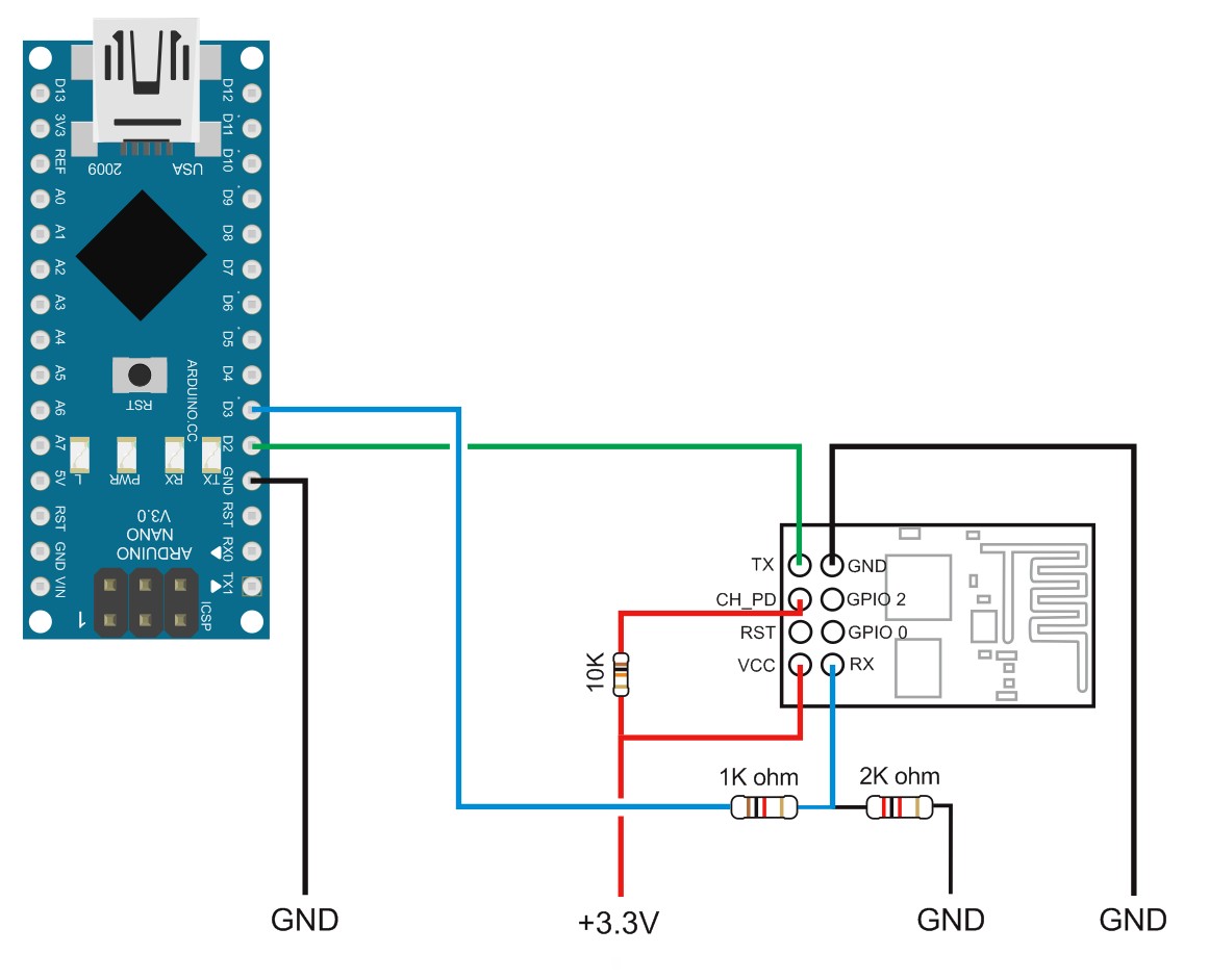
Following on from the FTDI + ESP8266 post, if you do not have a FTDI serial adaptor you can use an Arduino. Here is how to set up the Arduino to talk to the ESP8266.
Arduino, ESP32/8266, Bluetooth, and stuff
Following on from the FTDI + ESP8266 post, if you do not have a FTDI serial adaptor you can use an Arduino. Here is how to set up the Arduino to talk to the ESP8266.
Just started to play with the ESP8266-01 modules. Purchased from Taobao.
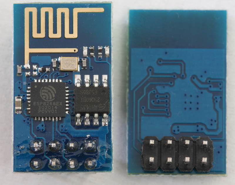
These, I believe, are version 2 and have the LEDs near the antenna. When first started they identify themselves as [Vendor:www.ai-thinker.com Version:0.9.2.4] and are version 018000902-AI03. This is a custom firmware from ai-thinker.
There seems to be quite a few different versions of similar modules. And the same module could have one of several firmwares.
In a previous post I showed how the HC-05 can auto connect to other Bluetooth devices by setting the HC-05 to pair with any device using CMODE=1. This is quick and easy but does not give any control over which other device the HC-05 connects to.
In this post I show how to set up the HC-05 to always connect to the same HC-06 (or HC-05 in Slave mode). For this we use PAIR, BIND, and LINK.
NOTE: There are now newer modules that use a 3.0-20170601 firmware. This guide does not work for these modules (AT+INQ gives an error). I do not have any of the new modules and cannot find a reliable supplier. I have ordered 3 sets of BT modules believing they were the newer ones only to receive old ones.
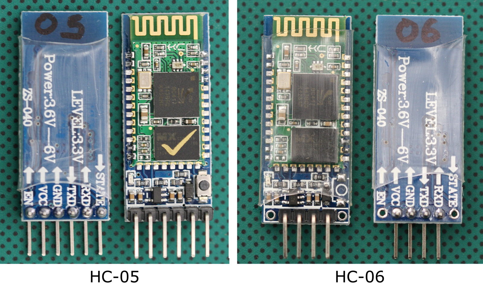
If you have not yet bought BT Classic modules. I recommend buying the original HC ones. These are slightly (just a little bit) more expensive but are well supported and full documentation is available. Original HC modules have the HC logo screen printed on the main BT board and the current boards have a blue LED top left.
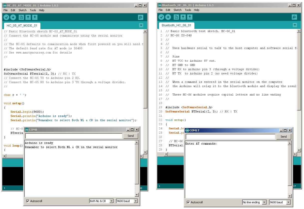
I am using 2 separate Arduino IDEs; version 1.6.3 which is installed, and version 1.0.5 which I run from a folder (it is the non install version). This allows me to use 2 IDEs at the same time, each connected to a different Arduino. It also gives me 2 serial monitors, one for each Arduino.
The modules used are the zs-040 versions of the HC-05 and the HC-06. The HC-05 has the Wavesen/HC firmware 2.0-20100601 and any any module running the same firmware will be the same.
The HC-05 has 2 AT command modes which I refer to as “mini” AT mode and “full” AT mode and some commands only work when in “full” AT mode. To enter “full” AT mode pin 34 needs to be HIGH and kept HIGH. To accomplish this I have made a connection from pin 34 to +3.3v. See the diagram below (or after the jump).
If you are not sure about At command mode take a look at Arduino with HC-05 (ZS-040) Bluetooth module – AT MODE
If you are not familiar with how the HC-06 and HC-05 work it may be worth while checking out some of the other posts:
HC-05 and HC-06 zs-040 Bluetooth modules
Arduino and HC-06 (ZS-040)
Arduino With HC-05 Bluetooth Module in Slave Mode
Connecting 2 Arduinos by Bluetooth using a HC-05 and a HC-06: Easy Method Using CMODE
Using the CMODE command we have an easy way to connect the HC-05 and the HC-06 (or 2 HC05s). When the HC-O5 is configured to pair with any address (AT+CMODE=1) it should connect to a Slave module automatically. No binding etc is required.
I am using the zs-040 modules with firmware 2.0-20100601 and other modules with the same firmware will be the same. If you have issues check the data sheet for your module.
I am using 2 different Arduino IDEs; version 1.0.5 and version 1.6.3. This gives me 2 separate serial monitors. The Arduino connected to the HC-05 is on COM8 and the Arduino using the HC-06 is on COM17
Since writing the below many more modules have been released using the zs-040 breakout boards. Some of the newer ones include modules with a version 3.0-20170601 firmware that work in a slightly different way. I still do not have any of these and so cannot help directly but searching for the firmware should get plenty of hits online and a good place to start is stack overflow and the Arduino forum.
Update 20.07.2017
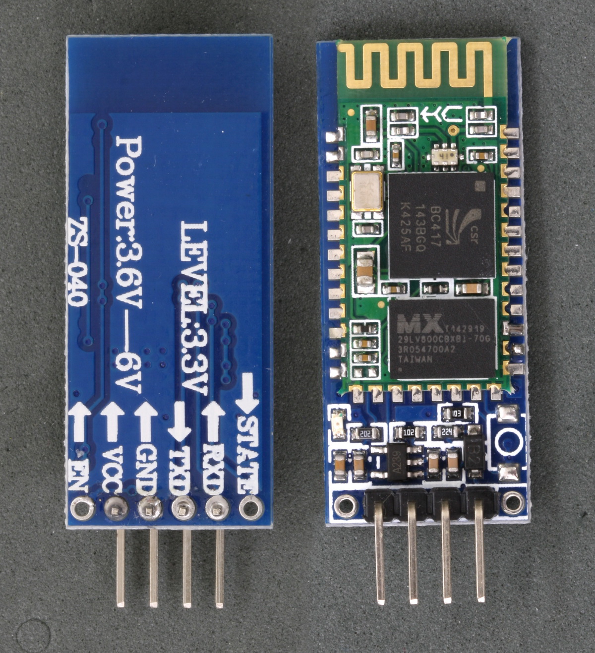
The zs-040 breakout boards are now being used for many different modules and you may not have the exact same boards as those shown below. The modules I am using here use the EGBT-045MS Bluetooth module and have the HC/Wavesen 2.0-20100601 firmware. They also have an EN pin rather than a KEY pin and they have a small button switch just above the EN pin.
There are now newer zs-040 modules that use the real HC SMD modules, these have a newer firmware and include a blue LED at the top right of the SMD daughter board.
There are also modules that use the same breakout board but have different board markings such as the fc-114 modules:
HC-05 FC-114 and HC-06 FC-114. First Look
HC-05 FC-114 and HC-06 FC-114. Part 2 – Basic AT commands
HC-05 FC-114 and HC-06 FC-114. Part 3 – Master Mode and Auto Connect‘
Updated on 18.07.2015.
Updated 01.12.2016
There are now newer HC-06s and HC-05s that use the zs-040 breakout boards. These new modules have a LED (usually blue) at the top left of the Bluetooth daughter board and have a different firmware to the below. See HC-06 hc01.comV2.0 for an introduction to the HC-06. I haven’t written up details on the HC-05 yet.
Here is the zs-040 version of the popular HC-05. The HC-05 is based on the EGBT-045MS Bluetooth module. It can operate as either a slave device or a master device. As a slave it can only accept connections. As a master it can initiate a connection.
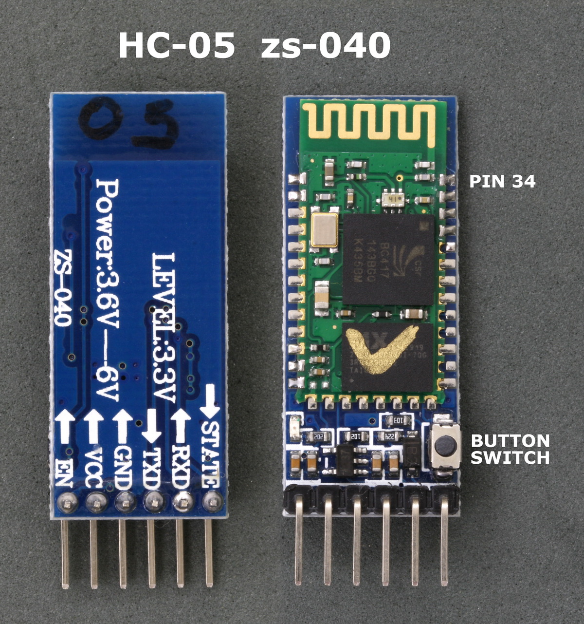
The EGBT-045MS Bluetooth modules (the smaller daughter board) is a 3.3v device. The HC-05 break out board has a 3.3v regulator that allows an input voltage of 3.6v to 6v but the TX and RX pins are still 3.3v. This means you can use the 5V out from the Arduino to power the boards but you cannot connect the Arduino directly to the HC-05 RX pin.
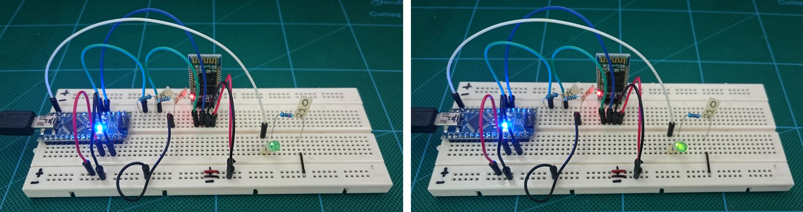
For the HC-05 RX pin (data in) we need to convert the Arduinos 5V to 3.3v. A simple way to do this is by using a voltage divider made from a couple of resistors. In my case I use a 1K ohm resistor and a 2K ohm resistor.
As a quick guide to the voltage divider; 1K + 2K = 3K. 1K is a third of 3K so it reduces the voltage by a third.
One third of 5V is 1.66 and 5-1.66 = 3.33 which is what we want. Putting the resistors the other way would reduce the voltage by 2 thirds.
For more information on voltage dividers have a look at the Sparkfun tutorial
Since the Arduino will accept 3.3 volts as HIGH you can connect the HC-05 TX pin (data out) directly to the Arduino RX pin (The 5V Arduino takes a voltage of 3V or more as HIGH).
This post follows on from Turning a LED on and off with an Arduino, Bluetooth and Android. Part II
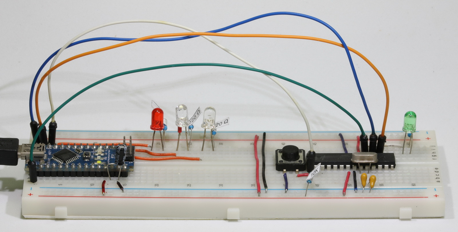
Now that we have two way communication working let’s add a couple more LEDs and two more switches.
In the first part I showed how to control a single LED from an app created in App Inventor. This worked OK but was very limited. You could control only 1 LED and the control was one way; from the app to the Arduino. What if you want to have 2 way control of the LED and to be able to also control the LED from the Arduino side? What if you want to control more than 1 LED?
In this guide we look at adding two-way communication. Here we control an LED but you could have it doing anything.
 In first example you could only control the LED from the Android app, here we extend the example so that we can also control the LED at the Arduino side. When the LED is turned on or off by the Arduino we want the button in the app to update to show the correct LED status.
The first example used methods only suitable for controlling one LED, this time we will try to make it so the Arduino sketch and also the AI2 app can be easily scaled and so once you have the basic app in place adding extra buttons and controls should be fairly straight forward.
Although I use a HC-06 in the below examples the HC-05 in slave mode can also be used.
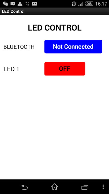
Using MITs app inventor it is fairly easy to create an app that can turn a LED on and off from an Android device.
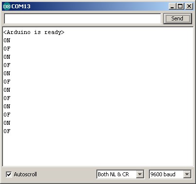
This is a fairly simply example of sending commands to the Arduino to turn a LED either on or off. The Android app sends ascii codes to the Arduino via the HC-06 BT module; “ON” for on and “OF” for off.
Load the app, connect to the HC-06 and then use the LED button to turn the LED on and off.
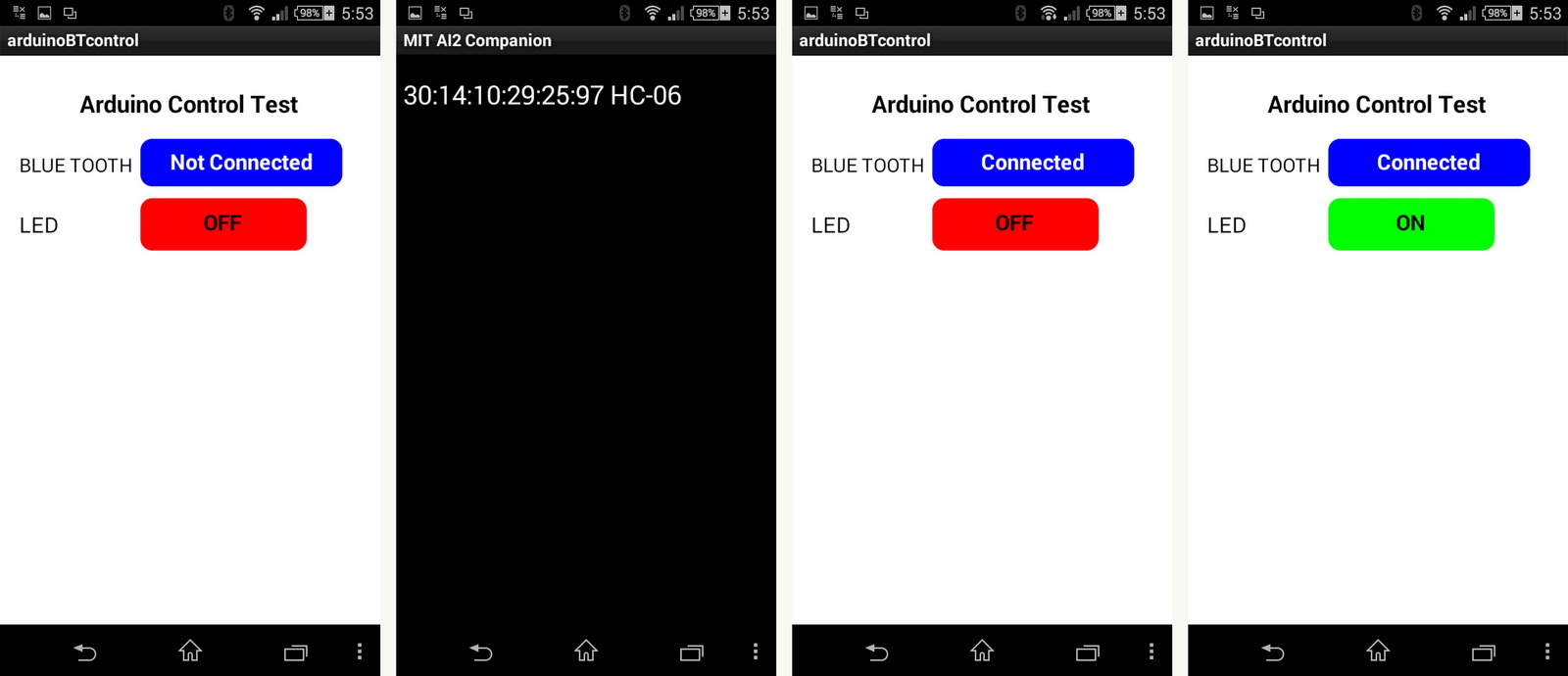
You can also open the serial monitor to see the commands as they are received
The HC-06 is a slave only BT module that is fairly easy to use with the Arduino using serial communication. Once it is connected it simply relays what it receives by bluetooth to the Arduino and whatever it receives from the Arduino it sends to the connected device. There are several slightly different versions of the HC-06, however, all seem to use the same firmware and have the same AT commands. The ones I have are labelled as zs-040. I also have some HC-05s which share the same PCB and are also labelled as zs-040.
The HC-06 defaults to AT mode at power on. This is indicated by a rapidly flashing LED. After the HC-06 is connected to another device the LED stops flashing and is constant on.
Update: If you have modules that have a blue LED in the top left hand corner then you have a newer model with a slightly different firmware although they should operate the same.
I recently bought some HC05s and HC-06 Bluetooth modules. These are pretty standard, especially when using with the Arduino and I was surprised at how easy it was to get basic serial communication working. There are several slightly different modules available. The ones I have are marked zs-040. The zs-040 boards differ from some of the other modules in that they have a EN pin rather than a KEY pin.
Part of programming stand-alone ATmega chips is setting the fuse bytes, these are special settings that can be used to change how the ATmega chips operate.
Some of the things you can do by changing the value of the fuses include;
There are many articles online but I could not find a single source that brought all the information together and fully explain what the fuses actually do.
It is important to remember that some of the fuse bits can be used to lock certain aspects of the chip and can potentially brick it (make it unusable). However, with a bit of care it is fairly straight forward to understand and use the fuse settings.
Disclaimer, I am relatively new to programming fuses and these are notes I wrote to help me remember things. The information is based on the data sheet for the ATmega chip, internet searches, and questions I asked on forums (especially the Arduino forum).
05.12.2015 Updated the photos.
In a previous post I showed how to make your own Arduino on a breadboard. The next step is programming it.
There are many guides online on how to use an Arduino to program a ATmega chip, two goods ones are:
Using an Arduino as an AVR ISP (In-System Programmer)
Nick Gammon’s guide
If you google “using Arduino as a programmer” you will find most of the results are for using an UNO, very few are for the Nano. One Nano guide I did find is at Lets Make Robots This explains how to set up the Nano but it does not clearly show how to program a stand alone Atmega chip.
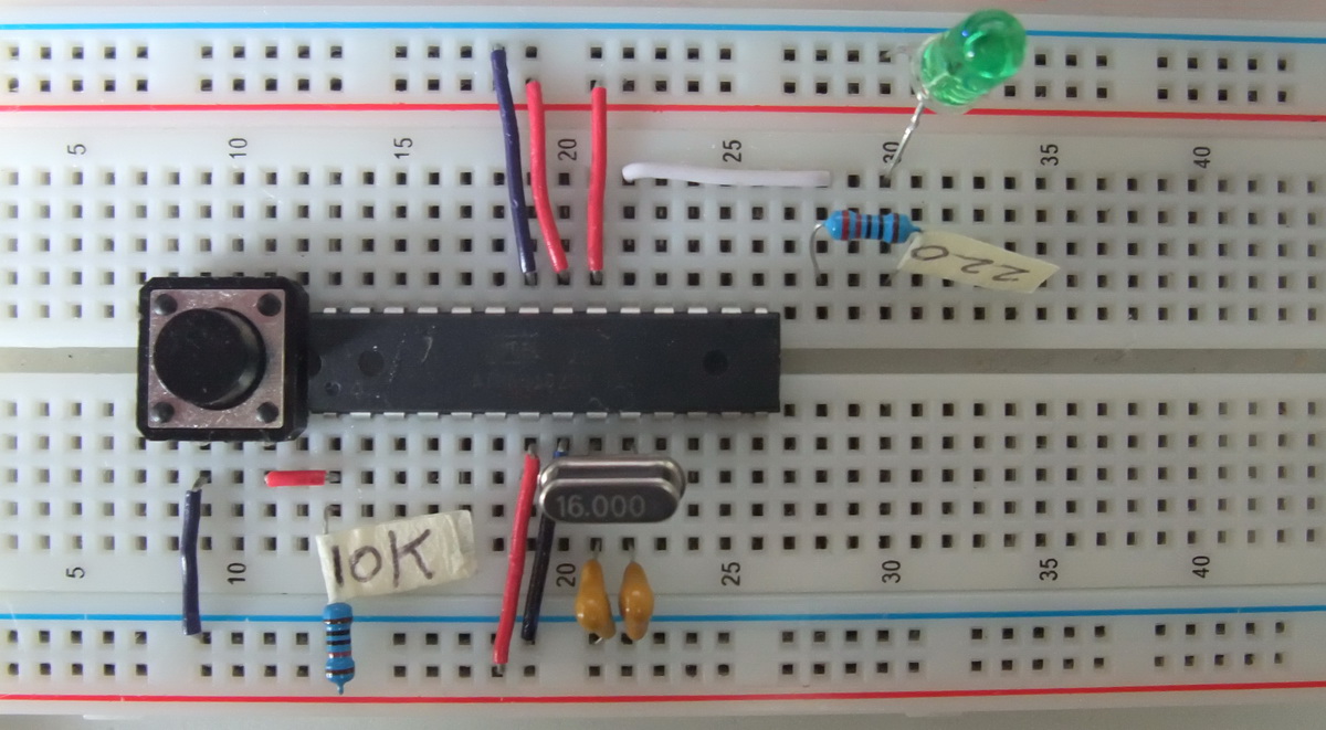
Here is my Arduino on a breadboard. There are many online guides for creating a breadboard Arduino. All are basically the same and follow the same connections. Some use pre-programmed chips, others use blank chips. My intention was to use a new blank ATmega chip (no boot loader) and use an Arduino Nano as an ISP programmer.
I have never been happy that my first version of the drop controller had 2 different power supplies; a 12 volt supply for the solenoid valves and a second 5 volt supply for the Arduino, so I looked for a way to share the 12 volt supply. After a short search I came across Derek Molloy’s video on Youtube. This describes making a 5 volt power supply from a mains adaptor.
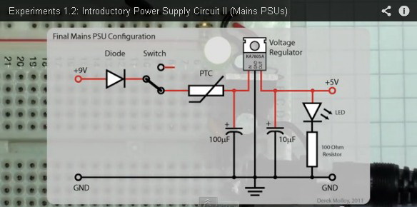
Full video after the break
Early water drop photos.Water, milk, coloured water and coloured milk.
The photos with black background done with the DropControl V1. Other photos done with V2.
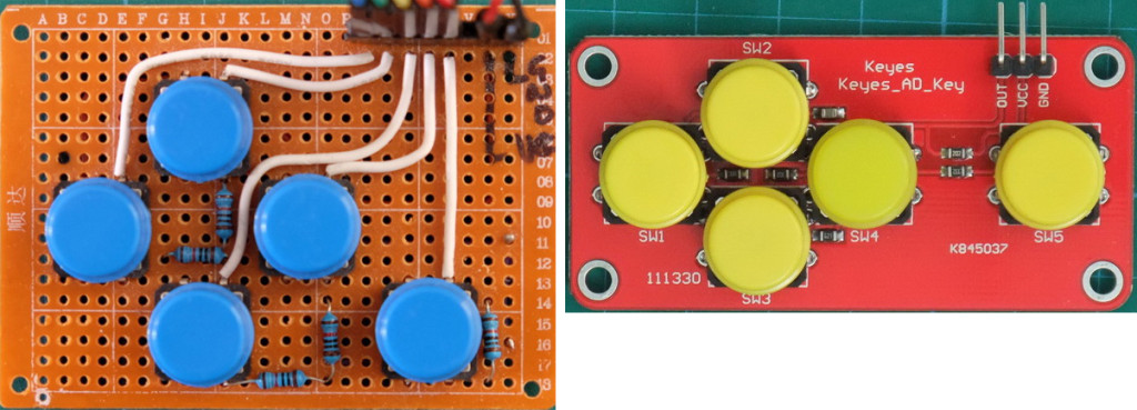
Digial keypad on the left. Analogue keypad on the right.
When I first started building the dropController and the camController I could not find suitable navigation keypads, the ones I did find were expensive or not really suitable, so I built my own. These were simple keypads and follow the normal wiring for press button switches. This means each of the push button switches is wired to a separate pin on the Arduino. This obviously means you need 5 pins. This was fine until I wanted to add extra solenoid valves and realized I didn’t have enough spare pins.
I starting looking for pre-made keypads again and came across the Keyes Keypad on Taobao. These are cheap and smaller than the keypads I made. They also use a single pin. These are analogue keypads that use a single analogue pin on the Arduino.
I am now starting to built a version 2 solenoid breakout board. While the first one works I have learnt a bit more about controlling the valves. Here is the diagram from Fritzing. Added resistors in line with the diodes. The flyback diode may cause the the solenoid to release too slowly. Adding the resistor … Read more
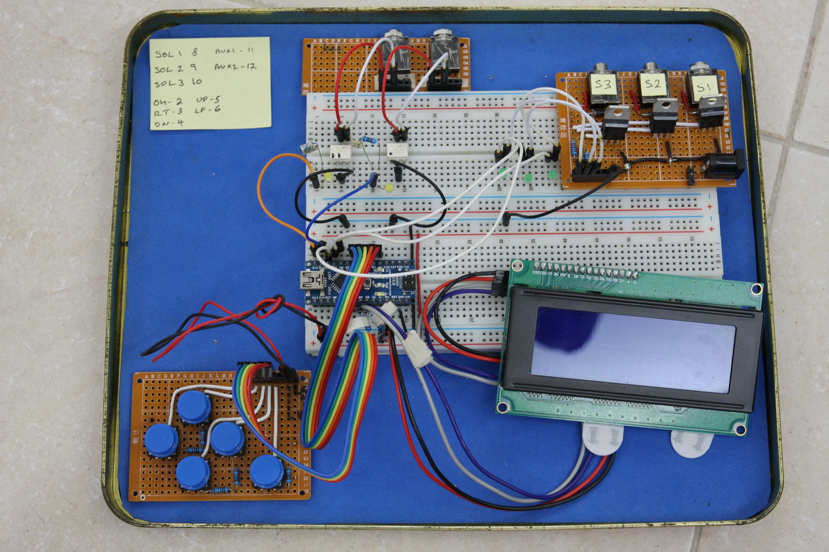
Here is my solenoid valve controller; version 0.1. It can control 3 solenoid valves and has 2 triggers.
It is designed to control the valves and then send a signal to another Arduino which controls the camera. However, it can be connected directly to a camera if required.
When building prototypes on breadboards I find it useful to have small pre-made components such as 3.5 stereo jack sockets configured to fit breadboards The 3.5 stereo socket is attached to a small piece of board and the connectors from the socket attached to pins that fit in to a breadboard. Red is VCC, black … Read more
In an early version of the camControl device (before the dropController) I used an interrupter/optoisolator to detect the water drops. The plan was to detect the water drop, wait a little bit and then activate the shutter.
There are various different kinds of photo interrupter, different shapes and different sizes but all do the same job.
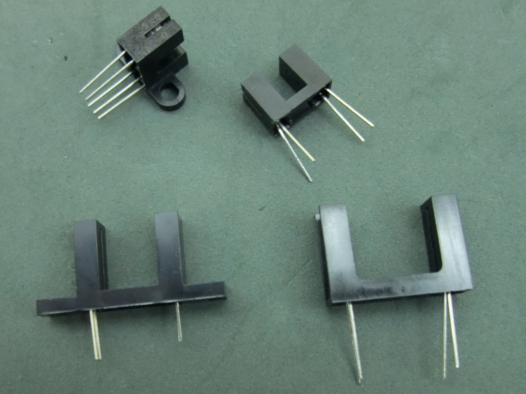
A photo interrupter has a LED at one side (normally IR) and a photo transistor at the other. When the LED in emitting light the photo transistor allows a current to flow. Remove the light and the current stops.
I started creating a controller using a single Arduino Nano on a breadboard. Although it was very basic it worked fairly well. It allowed me to control a solenoid valve and trigger the camera shutter. I also added basic camera control and a timelapse function (intervalometer). This part worked well. I could set the frequency … Read more
I had another session photographing water drops. The idea is to create two drops slightly apart. The first drop hits the water, rebounds and creates a column and then the second drop collides with the column. Sounds a lot easier than it really is. Here are some of the results. These are from plain water. … Read more
I wanted to try taking water drop photos and see what worked and what didn’t. Overall the results were better than I expected but not as good has I had hoped. Lighting is not good but I knew this from the beginning and concentrated on the drops and the timings. Working on the lighting can … Read more
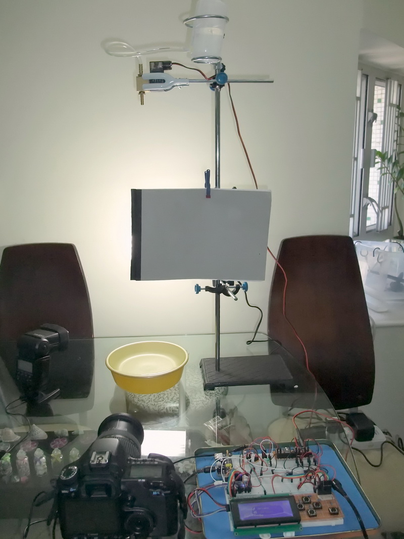
Here is the camera and stand setup. The stand is a 80cm lab stand. I bought 2 of these with various clamps and supports. Another Taobao special.