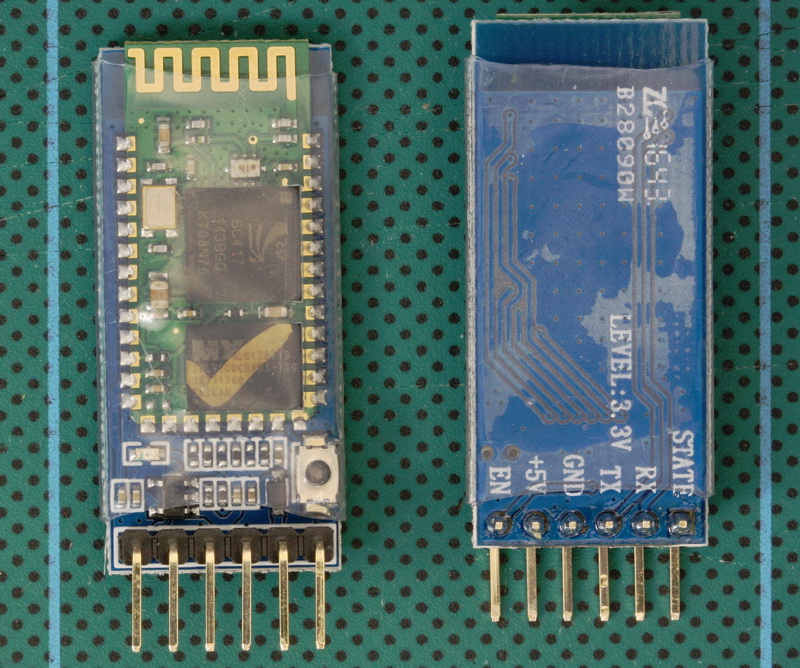
 The HC-05 (ZG-B23090W) uses a regular Bluetooth smd module based on the csr BC417 with a MX 29LV800CBXBI-70G flash memory chip. It appears to be using the HC/Wavesen 2010 firmware and a Google search for “HC-05 2.0-20100601” should give you plenty to read, including some of my older posts.
I have received a few comments about HC-06 and HC-05 modules that use a new breakout board (new to me at least). When I received the first comment I hadn’t seen these modules, by the time I had received the 4th or 5th comment the modules were all over Taobao so I decided to order a few (2 x HC-06 and 2 x HC05). I have no real use for these except to see if they are different to previous versions.
HC-05s
HC-05s are Bluetooth 2.0/2.1 EDR devices that have a serial UART layer on top of the Bluetooth. The UART layer makes them easy to use but hides the Bluetooth functions from the user. This is good if all you want is to make 2 things talk to each other. The HC-05 has two modes of operation; AT command mode and transmission mode. When in AT command mode all data received over the serial UART connection is treated as a command, and when in transmission mode, all data received over the serial UART connection is treated as data.
When in communication mode, if there is an active connection the data is broadcast to the connected device. If not connected, the data, disappears in to some mysterious void.
The HC-05 can operate as either a slave or master device. Slave devices cannot initiate connections, they can only accept them. Master devices can initiate and (depending on the actual module) sometimes accept them. If you want to use the module with a mobile device such as an Android phone, the phone will be the master device and so the HC-05 will need to be the slave. If you want to link two HC-05s, one will need to be a master and the other one a slave.
HC-05 (ZG-B23090W): Basic Specs
Bluetooth 2.0 EDR
Based on the csr BC417 chip
Firmware is VERSION: 2.0-20100601 which is by Wavesen.
Can be a slave or a master device
Has 2 modes: AT mode and communication mode.
Default baud rate for AT mode is 38400
Default baud rate for communication is 9600
AT commands can be either lowercase or uppercase
AT commands require “\r\n” line endings
HC-05 (ZG-B23090W): First try
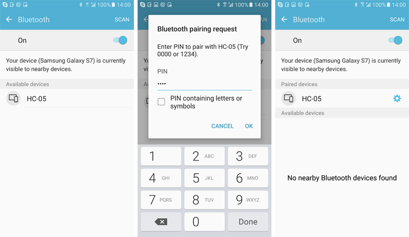
The first thing with any new Bluetooth module is to power it up, see if they work and what name they transmit. These modules seem to work fine, they transmit “HC-05″ and they pair with the PIN “1234”. This is fairly standard.
HC-05 (ZG-B23090W): LED
When first powered, the LED flashes quickly about 10 times a second.
After pairing the LED flash rate changes to a single quick flash every couple of seconds.
When connected, the LED blinks quickly twice every couple of seconds.
In AT command mode (the 38400 baud rate one) the LED blinks 1 second on, 1 second off (maybe a little slower).
HC-05 (ZG-B23090W): Communication and AT commands
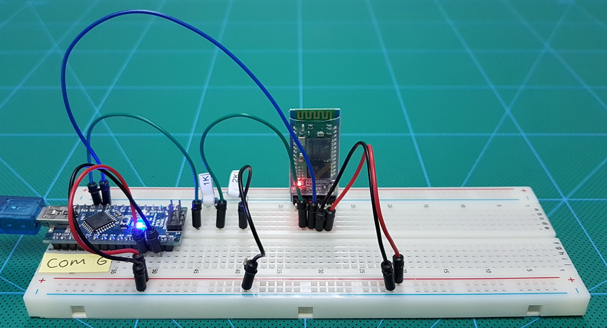
Next up is to see if we can talk to them using AT commands. There are a couple of ways to connect serial Bluetooth modules to a PC; via a serial UART adapter, or, by using an Arduino and a serial-in serial-out sketch. I am using an Arduino and a serial in – serial out sketch.
The Arduino Sketch
The sketch takes anything entered in to the serial monitor, echos it back to the serial monitor main window and then sends it to the Bluetooth module. Anything received from the Bluetooth module is displayed in the serial monitor.
To highlight the user entered text, a “>” character is displayed at the start of the line.
Note that we are using 2 serial connections. One using the serial monitor on the host computer and one to talk to the Bluetooth module. These are separate and different and have separate baud rates which do not need to be the same. This can be a little confusing to people new to the Arduino.
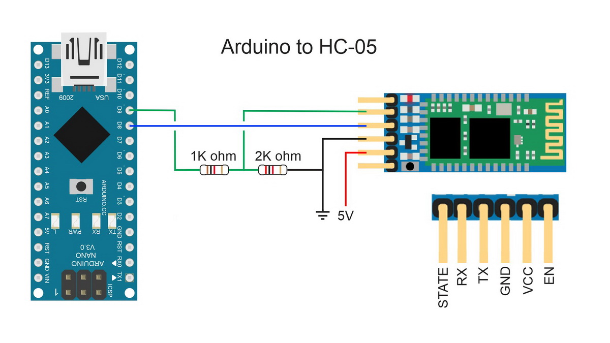
// Sketc: basicSerialWithNL_001 // // Uses hardware serial to talk to the host computer and software serial // for communication with the Bluetooth module // Intended for Bluetooth devices that require line end characters "\r\n" // // Pins // Arduino 5V out TO BT VCC // Arduino GND to BT GND // Arduino D9 to BT RX through a voltage divider // Arduino D8 BT TX (no need voltage divider) // // When a command is entered in the serial monitor on the computer // the Arduino will relay it to the bluetooth module and display the result. // #include <SoftwareSerial.h> SoftwareSerial BTserial(8, 9); // RX | TX const long baudRate = 38400; char c=' '; boolean NL = true; void setup() { Serial.begin(9600); Serial.print("Sketch: "); Serial.println(__FILE__); Serial.print("Uploaded: "); Serial.println(__DATE__); Serial.println(" "); BTserial.begin(baudRate); Serial.print("BTserial started at "); Serial.println(baudRate); Serial.println(" "); } void loop() { // Read from the Bluetooth module and send to the Arduino Serial Monitor if (BTserial.available()) { c = BTserial.read(); Serial.write(c); } // Read from the Serial Monitor and send to the Bluetooth module if (Serial.available()) { c = Serial.read(); BTserial.write(c); // Echo the user input to the main window. The ">" character indicates the user entered text. if (NL) { Serial.print(">"); NL = false; } Serial.write(c); if (c==10) { NL = true; } } } |
Build the circuit and upload the sketch. When first connected the LED on the HC-05 should be blinking quickly (about 10 times a second). This indicates communication mode. To use AT commands we need to put the HC-05 in to AT command mode.
HC-05 (ZG-B23090W): AT command mode
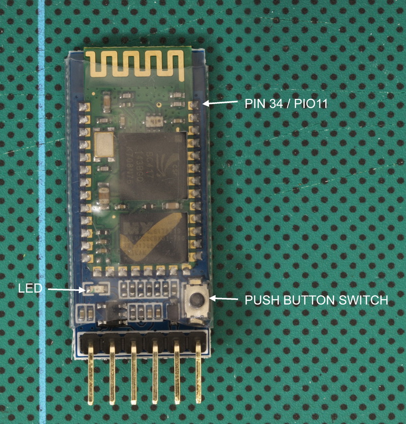
To put the HC-05 in to AT command mode pin 34/PIO11 has to be HIGH on power up.
On the HC-05 breakout board (bottom right corner) there is a small push button switch, this, when closed, connects pin 34/PIO11 to +3.3v, therefore, to put the HC-05 in to AT command mode, we can use the button switch.
To enter AT mode using 38400 baud rate;
– power off the module,
– press and hold the small button switch,
– re-apply power while holding the button switch closed,
– when you see the LED come on, release the button switch.
When in AT command mode the LED flash rate will change to 1 second on, 1 second off (or maybe a little slower).
For AT command mode to be fully operational pin 34/PIO11 should be kept HIGH but this is not possible when using just the push button switch. Some commands do not work when in AT command mode and pin 34 is not HIGH. Therefore, some commands need you to close the switch before sending.
If you are doing a lot of work in AT command mode you could solder a wire directly to pin 34 and connect to +3.3v.
To return to communication mode, set pin 34 not HIGH (LOW or floating) and cycle the power to the module.
The Wavesen 2010 firmware has a bug feature that allows you to enter a kind of mini AT mode at the user settable communications baud rate. In this mode not all commands work, “AT+NAME?” being one of them. Therefore, I don’t recommend this mode and suggest you use the full 38400 AT command mode.
To enter the mini AT command mode, power on the module first and then close the button switch. The LED flash does not change.
HC-05 (ZG-B23090W): Serial monitor and AT commands
Assuming we are in AT command mode let’s try some simple commands.
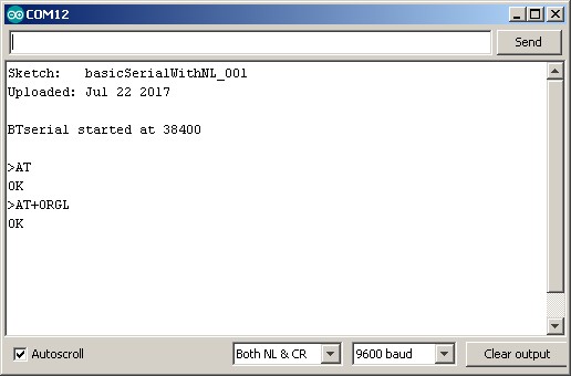
The HC-05 requires AT commands to include line endings (\r\n) so after opening the serial monitor make sure “Both NL & CR” is selected. I am using uppercase commands to keep things clear.
![]()
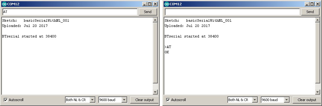
Let’s have any easy start with “AT”. If everything is connected corrected and you successfully entered AT mode you should get a “OK” reply
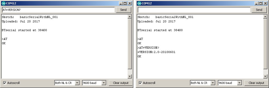
and to check what firmware the modules are running enter “AT+VERSION?”
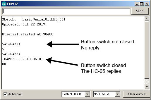
To see what name the modules currently have, use “AT+NAME?”. Note that “AT+NAME?” requires pin 34/PIO11 to be HIGH so, just before sending the command, close the button switch. If you send the command and pin 34/PIO11 is not HIGH the HC-05 will not reply.
“H-C-2010-06-01” is the firmware default name which comes back after a factory reset. The name the modules were set with when I bought them was “HC-05”.
“AT+ORGL” reset to factory defaults.
HC-05 (ZG-B23090W): Downloads
HC-05 B28090W Bluetooth module Data Sheet English
HC-05 B28090W Bluetooth module Data Sheet Chinese
More information
For more information and details about the AT commands see HC-05 with firmware 2.0-20100601
Hi, i did everything right, but at AT Commands i type “AT” and the module dont return me “OK”, i set the boud rate 38400 and nothing! What can i do?
If you are sure you have the same module than double check all connections. Then check again.
Check the voltage divider and make sure you have the correct resistors and that they are in the correct position.
If you are not sure you have the same module you need to find out which one you have. There are many different ones and there are many different firmwares.
I’m trying to change the PSWD to my module, but I can’t, the name I changed, I think becouse i’m using the Bluetooth HC-05 version 3.0. Could any body tell me how can I do that please? thank’s.
hi
how can i erase the flash..on chip..
can help
hi, i am trying to change the module as a master , but it does not works ,”AT+ROLE=1″ is not respond
Hi Martyn,
Thank you for all of your information on BT.
It appears that all HC-05 modules are being shipped with Version 3.0 firmware. After much work I can communicate with the module and execute the AT commands however I’m not sure the commands work as I expect in Version 3.0.
I execute the PAIR, BIND, LINK sequence with an HC-06 and confirm that the HC-05 is paired and bound to the HC-06. Then I change the HC-05 CMODE to 0 so the HC-05 will only pair with the bound HC-06. This is where the trouble starts. The HC-05 and HC-06 pair OK but the HC-05 will pair with other HC-06 modules that are not paired and bound.
Does anyone have information on the Version 3.0 firmware? It seems like there must be other AT commands or maybe PAIR and BIND don’t work in the new firmware. Is it possible to downgrade V3 HC-05 to V2? If yes where can you get V2 firmware and what is the procedure?
Thanks
WE NEED HC-05 200 NOS . KINDLY GIVE YOUR BEST PRICE
Unfortunately I don’t sell the modules and if I did I would not be the cheapest.
Hi, I used a few HC-05 modules before and I made an application for communicating with it and it worked fine. Now I purchased a new one from a local shop here in India. But it didn’t work with my application. The placement of two ICs is somewhat different from previous ones and nothing marked on its backside except pin details. Then I purchased two more samples, one from another local shop and one from online. But all three are absolutely the same. By using at commands I checked the firmware version of the new HC-05 modules. AT+VERSION?
+VERSION:4.0-20190815. But didn’t find any details about this version. Is this version different from normal 2.1?
I suspect it is different but I don’t have any modules with this firmware so cannot confirm for sure.
Because there are now so many poorly supported firmware I recommend the original Waven/HC01 boards. These are very reliable and well supported.
Thanks for the reply,
one more question is it possible to change the firmware back to 2.0?.
Hi, I have a hc-05 verion: 4.0-20190815
in AT-mode:
AT ok
AT+NAME , AT+PSWD, AT+UART, AT+CMODE are work properly
but
for
AT+POLAR=1,0
or AT+POLAR?
reply: ERROR:[0]
please help
Hello, I bought an HC-05 and the first chip on the top of the module is smaller than the most common one. With this model, I am unable to change the PIN via AT command. It works to change the bound and name, but the password does not work. What would be the suggestion? Is there a way to change the firmware? If there is, could you please explain.