There are many types of optocoupler and you chose one based on the requirements of your circuit. My intention was to create a automatic shutter trigger for my Canon camera, so the circuit was a 5V Arduino and a Canon 40D which has about 3.2V on the shutter release connections. Due to the relatively low voltages there are many suitable optocouplers to pick from. I already had a Fairchild 4N26 so this is the one I used.
4N26
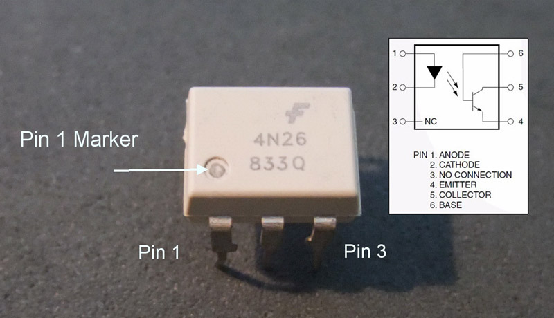
Optocouplers are digital switches. They work by using an LED emitter paired with a photo detector transistor. This means they can be used to allow one circuit to switch a separate circuit without having any electrical contact between the two. Basically, if you put a current through pins 1 and 2 and light the LED the photo detector transistor detects the light from the LED and allows a current to flow through pins 5 and 4. No current on pins 1 and 2 means current does not pass through pins 5 and 4.
Pins 1 and 2 go to the Arduino, pins 5 and 4 go to the cable release. Note that the +5 volts (VCC) from an Arduino digital pin goes to pin 1 and Arduino ground goes to pin 2. You need to add a suitable resistor to the input, see below. The shutter wire from the shutter release cable goes to pin 5 and ground from the shutter release goes to pin 4. It will not work if you get them the wrong way-a-round.
The main things you need to know when choosing an optocoupler are:
1. The current transfer ratio
2. The switching time (bandwidth)
3. The collector / emitter voltage limit
4. The input current (IF).
Current transfer ratio (CTR).
The CTR is the ratio of the phototransistor collector current compared to the LED emiiter forward current. It is similar to the DC current amplification ratio of a transistor and is expressed as a percentage.
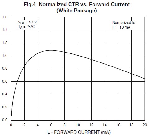
Most optocouplers have a CTR of between 10% and 50%. The Fairchild 4N26 has a CTR of about 20%. The value of the CTR changes depending on the input current and the ambient temperature. As a general guide, optocouplers are most efficient at about 10mA. CTR=(IC/IF)*100. Bear in mind this is a general guide only and you should check the data sheet for exact information. According to the below diagram, taken from the data sheet, the Fairchild 4N25 is most efficient at about 6mA (top of the curve).
The CTR depends on the LED input current (IF) and the CTR decreases from a maximum point when the input current is both increased and decreased. If you look at the below diagram, the top of the curve is around the 6mA point. This is where the chip is most efficient. You will notice that the curve is far steeper on the small current side (IF 0mA to 6mA) compared to the high current side (IF 6mA to 20mA) and it is therefore, better to have slightly more current on the input side rather than slightly too little. 1mA too little has a far bigger effect than 1mA too much.
The CTR depends upon the current gain (hfe) of the transistor, the supply voltage to the phototransistor, the forward current through the LED and the operating temperature. CTR=(IC/IF)*100
The switching time
The is the time it takes for the optocoupler to switch on or off. The 4N26 has a turn on time of 2μs (2 microseconds or 2 millionths of a second) and a turn off time of 2μs. This is more than sufficient for my needs.
The collector / emitter voltage limit
This is the maximum voltage the optocoupler can handle on the output side. For the 4N26 it is 30V. Since I want to use it on a Canon 40D which has about 3.2V on the shutter release cable it is more than enough.
The input current
This is used to calculate the resistor value on the input side. This is typically about 10mA.
You could add a diode to the input side to protect the device from reverse voltage but since the voltages I am using are below the chips reverse voltage threshold a diode is not required. The 4N26 has a maximum reverse voltage of 6V (taken from the data sheet) and since I am driving it from a 5V Arduino I will not damage the chip if I get the wires the wrong way around.
The 4N26 I have has a forward voltage of 1.2V (based on 10mA). So, using r = v / i we need a 5v – 1.2v = 3.8v / 0.010 = 380 ohms resistor on the input side. 380 is the minimum and higher values will also work (you can use higher not lower). The nearest I had was 470ohm.
Depending on your circuit you may need to add a resistor on the other side of the optocoupler as well.
Test circuit
To get started and to make sure I had everything working before attaching the camera I created a test circuit. This is simply the optocoupler with an Arduino connected on one side and a LED and battery on the other. The optocoupler is connected to pin 12 on the Ardunio. The 2 circuits are completely separate. There is no electrical contact between the Arduino side and the battery/LED side. I am pretty sure though, if you fed enough current through one side and exceeded the limits of the chip you would cause a short.
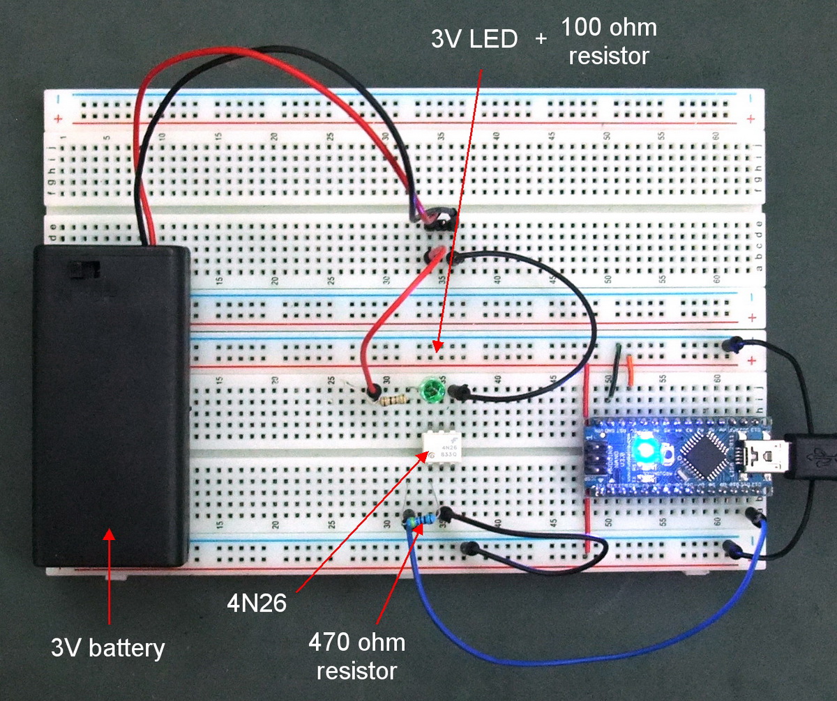 I included a small resistor on the output side.
To test the circuit I modified the Blink sketch by adding the optocoupler to pin 12 and made it HIGH / LOW at the same time as the LED pin.
/* Blink Turns on an LED on for one second, then off for one second, repeatedly. This example code is in the public domain. */ // Pin 13 has an LED connected on most Arduino boards. // give it a name: int led = 13; int opto = 12; // the setup routine runs once when you press reset: void setup() { // initialize the digital pin as an output. pinMode(led, OUTPUT); pinMode(opto, OUTPUT); } // the loop routine runs over and over again forever: void loop() { digitalWrite(led, HIGH); // turn the LED on (HIGH is the voltage level) digitalWrite(opto, HIGH); delay(1000); // wait for a second digitalWrite(led, LOW); // turn the LED off by making the voltage LOW digitalWrite(opto, LOW); delay(1000); // wait for a second } |
This worked fine, the green LED flashed in sync with the LED on the Arduinos pin 13. The the next stage was to attach the camera.
One of the easiest to understand I have found.
Making a project for my class, and this is the tutorial I needed. Thanks!