There are several ways you can connect an Arduino to a DSLR so that you can use the Arduino to activate the shutter. I chose to use an optocoupler, sometimes called an optoisolator.
Optocoupler
There are many types of optocoupler and you chose one based on the requirements of your circuit. My circuit is a 5V Arduino and a Canon 40D which has about 3.2V on the shutter release. Due to the relatively low voltages there are many suitable optocouplers to pick from. I already had a Fairchild 4N26 so this is the one I used.
4N26
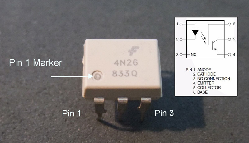
Optocouplers are digital switches. They work by using an LED emitter paired with a photo detector transistor. This means they can be used to allow one circuit to switch a separate circuit without having any electrical contact between the two. Basically, if you put a current through pins 1 and 2 and light the LED the photo detector transistor detects the light from the LED and allows a current to flow through pins 5 and 4. No current on pins 1 and 2 means current does not pass through pins 5 and 4.
Pins 1 and 2 go to the Arduino, pins 5 and 4 go to the cable release. Note that the +5 volts (VCC) from an Arduino digital pin goes to pin 1 and Arduino ground goes to pin 2. You need to add a suitable resistor to the input, see below. The shutter wire from the shutter release cable goes to pin 5 and ground from the shutter release goes to pin 4. It will not work if you get them the wrong way-a-round.
The main things you need to know when choosing an optocoupler are:
1. The current transfer ratio
2. The switching time (bandwidth)
3. The collector / emitter voltage limit
4. The input current (IF).
Current transfer ratio (CTR).
The CTR is the ratio of the phototransistor collector current compared to the LED emiiter forward current. It is similar to the DC current amplification ratio of a transistor and is expressed as a percentage.
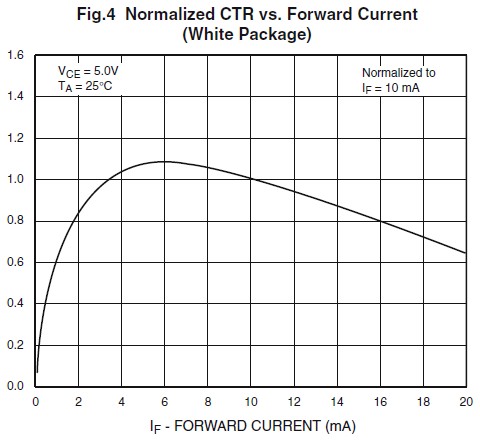
Most optocouplers have a CTR of between 10% and 50%. The Fairchild 4N26 has a CTR of about 20%. The value of the CTR changes depending on the input current and the ambient temperature. As a general guide, optocouplers are most efficient at about 10mA. CTR=(IC/IF)*100. Bear in mind this is a general guide only and you should check the data sheet for exact information. According to the below diagram, taken from the data sheet, the Fairchild 4N25 is most efficient at about 6mA (top of the curve).
The CTR depends on the LED input current (IF) and the CTR decreases from a maximum point when the input current is both increased and decreased. If you look at the below diagram, the top of the curve is around the 6mA point. This is where the chip is most efficient. You will notice that the curve is far steeper on the small current side (IF 0mA to 6mA) compared to the high current side (IF 6mA to 20mA) and it is therefore, better to have slightly more current on the input side rather than slightly too little. 1mA too little has a far bigger effect than 1mA too much.
The CTR depends upon the current gain (hfe) of the transistor, the supply voltage to the phototransistor, the forward current through the LED and the operating temperature. CTR=(IC/IF)*100
The switching time
The is the time it takes for the optocoupler to switch on or off. The 4N26 has a turn on time of 2μs (2 microseconds or 2 millionths of a second) and a turn off time of 2μs. This is more than sufficient for my needs.
The collector / emitter voltage limit
This is the maximum voltage the optocoupler can handle on the output side. For the 4N26 it is 30V. Since I want to use it on a Canon 40D which has about 3.2V on the shutter release cable it is more than enough.
The input current
This is used to calculate the resistor value on the input side. This is typically about 10mA.
You could add a diode to the input side to protect the device from reverse voltage but since the voltages I am using are below the chips reverse voltage threshold a diode is not required. The 4N26 has a maximum reverse voltage of 6V (taken from the data sheet) and since I am driving it from a 5V Arduino I will not damage the chip if I get the wires the wrong way around.
The 4N26 I have has a forward voltage of 1.2V (based on 10mA). So, using r = v / i we need a 5v – 1.2v = 3.8v / 0.010 = 380 ohms resistor on the input side. 380 is the minimum and higher values will also work (you can use higher not lower). The nearest I had was 470ohm.
Depending on your circuit you may need to add a resistor on the other side of the optocoupler as well.
Test circuit
To get started and to make sure I had everything working before attaching the camera I created a test circuit. This is simply the optocoupler with an Arduino connected on one side and a LED and battery on the other. The optocoupler is connected to pin 12 on the Ardunio. The 2 circuits are completely separate. There is no electrical contact between the Arduino side and the battery/LED side. I am pretty sure though, if you fed enough current through one side and exceeded the limits of the chip you could cause a short.
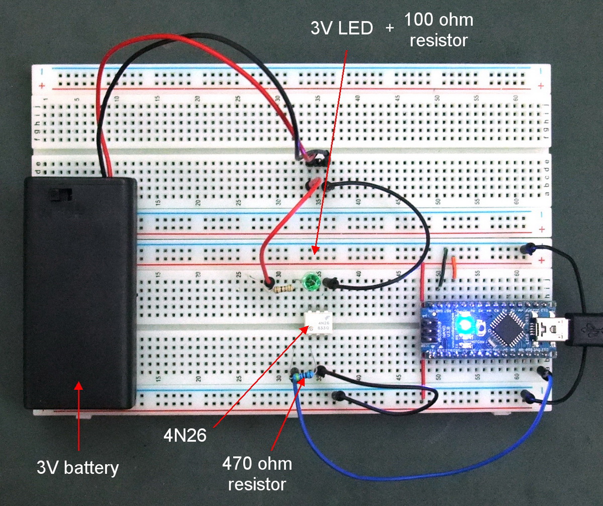 When using LEDs you should always add a resistor, here I have included a 100 ohm resistor.
LEDs will keep pulling current until something breaks. Therefore, you should always include a resistor to limit the amount of current the LED can draw.
To test the circuit I modified the Blink sketch by adding the optocoupler to pin 12 and made it HIGH / LOW at the same time as the LED pin.
/*
Blink
Turns on an LED on for one second, then off for one second, repeatedly.

This example code is in the public domain.
*/

// Pin 13 has an LED connected on most Arduino boards.
// give it a name:
int led = 13;
int opto = 12;

// the setup routine runs once when you press reset:
void setup()
{
// initialize the digital pin as an output.
pinMode(led, OUTPUT);
pinMode(opto, OUTPUT);
}

// the loop routine runs over and over again forever:
void loop()
{
digitalWrite(led, HIGH);   // turn the LED on (HIGH is the voltage level)
digitalWrite(opto, HIGH);
delay(1000);               // wait for a second
digitalWrite(led, LOW);    // turn the LED off by making the voltage LOW
digitalWrite(opto, LOW);
delay(1000);               // wait for a second
}
This worked fine, the green LED flashed in sync with the LED on the Arduinos pin 13. The the next stage was to attach the camera.
Shutter Release Cable
As mentioned, I have a Canon 40D which uses a proprietary N3 connector. I already had a Canon RS-80N3 shutter release cable but since it was expensive I did not want to destroy it. Instead I bought a cheap compatible release cable for about $5.
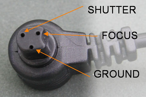
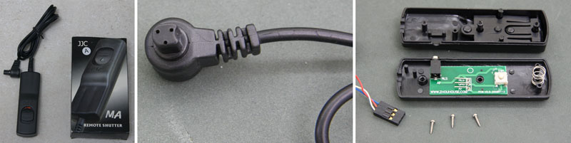
I was going to cut off the end of the cable but when I opened it I had a pleasant surprise. The cable had a 0.1 inch header attached to it. This meant I could easily connect it to a breadboard. For this particular cable; white is ground, red is +3V shutter release and blue is +3v focus. Other makes will have different colours.
The shutter release is basically a couple of contact switches. Connect the focus pin to ground and the camera focuses. Connect the shutter pin to ground and a shot is taken. This means to wire up the shutter release all you need to is introduce some kind of switch. You can do this by directly connecting the shutter release cable to the Arduino. The camera puts about 3.2 volts through the shutter release which the Arduino can handle. However, connecting the two devices directly is not a good idea. Should something go wrong you could damage the camera. This is where the optocoupler comes in.
Connecting the camera to the Arduino.
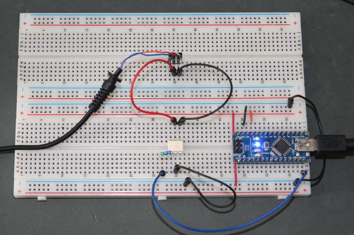
All I have done is replaced the LED and battery with the shutter release cable.
Using the same sketch as above, I connected the camera and turned on the Arduino. The sketch activated the shutter every 2 seconds as expected.
[evp_embed_video url=”https://www.martyncurrey.com/wp-content/uploads/2013/11/ArduinoShutterRelease.mp4″]
Next Steps
Although triggering the shutter on its own works for the Canon cameras it may not work on all brands. Ideally you also need to trigger focus and some things (like bulb mode) will only work when both focus and shutter are triggered together.
Great tutorial, works a treat as a basic shutter release. I will be using the arduino to control the camera shooting interval and will also be using a motorized dolly for the movement of the camera. This tutorial allows anyone to be able to use their arduino to control their camera. Thanks heaps! Adam.
Thank you for posting this.
I followed it and it worked first time.
Hi there! This post helped me a lot. Thanks.
Thanks for the write-up, and the clear explanation of optocouplers!
Best beginner’s tutorial on using optocouplers I’ve come across. Thank you!
Thank you very much for this beginner tutorial.
You’re answering every single question I can imagine!!
Had already a solution with transistors and it worked well. But I have done a mistake with my circuit and now the mainboard of my canon 550d is damaged. Cant be repaired and a new one cost around 300 Euro…. so for everyone reading this, dont use transistors if you dont know much about electronics! This tutorial is a far better solution with more security!!
Regards from germany
Hi! It’s a very interesting tutorial. After seeing dozens of similar tutorials to get something done, i select just a few, and yours is one of them. It’s an elemental tutorial about using optocoupler, thanks!!
I’d like to use this in another project, and i’d like to say it here in order to get some help or ideas :)
The main idea is: PIR sensor -> arduino -> optocoupler -> camera
I can use PIR as a sensor; i can read sensor data; i can use opto as switch, but: could i use any simple bad digital camera? I have dissassembled a few of them, diferent kinds, and in a simple example: must power on the camera, and press shutter. Could i do this with optos?
Next step is building a simple IR light emiter, so camera (IR hacked) can see at night.
Sorry about my english, and excuse me if my message looks confusing. Feel free to email me if you can /want to help me or comment something :)
Thanks!!
JAvi
This is certainly possible but beyond the scope of this tutorial.
The only time I used a camera that did not have a shutter release connection I soldered wires directly to the shutter button switch. This kind of worked but I had other issues like when the camera went in to sleep mode.
This is useful. Thanks. I came across another interesting tutorial online which I am struggling to understand. https://www.youtube.com/watch?v=b6ZagKRnRdM
It uses an optocoupler to trigger a relay. The first version of the circuit makes sense to me, but the second one is more interesting since it removes the transistor. That said, what throws me off (at the end of the video; it the last circuit @ 8:32) is that current flows from VCC into the GPIO but if the GPIO outputs 3.3VDC, there seems to be a problem. I’m used to circuits going from VCC into GND so something like that diagram confuses me.
Most hobbyists (myself included) would have the connections the other way around and use the GPIO pin to supply VCC to the optocoupler and this is how I have the connections in the example above.
The circuit in the video is using the GPIO pin to sink the current rather than supply it. That means when the GPIO pin goes low, current flows from VCC to the pin and the circuit turns on. Bringing the pin high balances the current so there is no current flow and the circuit turns off.
Hi Martyn,
Thanks for the tutorial.
On another site it was suggested that one should trigger focus first and then shutter release, though I’m not sure why.
I’m thinking of duplicating the circuit (i.e. two separate optocouplers, two separate data outputs), one for focus and the other for shutter. Any thoughts on that?
Cheers
PG
Triggering focus and the shutter is the correct way to do it.
The above was an early experiment which developed in to a camera trigger/ water drop device which you can see at http://www.dropcontroller.com/dropcontroller-2/. Take a look at the camera triggers in the circuit diagram.
Excellent post/tutorial. This is exactly what I needed for my DIY motorized camera slider with shutter control from Arduino.
Thank you very much for your very easy to understand explanation.
Thanks heaps for your help! I needed to use my Photon to reboot a frozen PC at a rather remote location, so using this example and doubling it, I am now able to use the Reset button on one 4n28, and the Power button with the other 4n28. Works a treat, but in the PC mainboard pins, you have to make sure it’s around the correct way for the trigger to work. Trial and error fixes that :)
I am new with electronics, so here is a basic question.
Why would one use optocoupler for this and not a reed relay? Isn’t the latter even simpler?
In the case of N3 it seems the remote controls just directly connect the focus and/or shutter release to ground when button is pushed.
It is my understanding that if I use a small enough reed relay, I would not need any resistors?
una mierda porque no te suicidas,
saludos
tu jefa